Note : Les descriptions sont présentées dans la langue officielle dans laquelle elles ont été soumises.
CA 02597366 2007-08-15
-1-
Title: ROOF VENT FOR VENTING A BUILDING ENCLOSURE
FIELD OF THE INVENTION
This invention relates generally to the field of venting devices, and in
particular, to venting devices for venting building enclosures.
BACKGROUND OF THE INVENTION
Virtually all buildings and enclosures where human activity takes place
require venting of one type or another. The type of venting device employed
will depend on the kind of enclosure to be vented. For example, bathrooms
containing showers typically have active vents with fans to vent steam to the
outdoors. Kitchens, particularly in restaurants and hotels, similarly have
powered vents for removing odours, smoke and steam to the outdoors.
Other types of enclosures, such as attics and yard sheds, do not require
active venting. However, such enclosures do typically require a passive vent
to allow for air flow from the enclosure to the atmosphere. Such venting is
required, for example, to prevent a buildup of moisture in the enclosure.
Passive vents do not include a mechanism for forcing air out of the enclosure.
Rather, they simply include a vent structure, in the form of an air passageway
which allows air to flow through the vent structure.
Because passive vents simply allow air to flow in and out through an
opening in the enclosure, they typically include a screen that blocks animals
or
unwanted objects from entering the enclosure through the opening, but still
allows air flow. The presence of the screen tends to reduce airflow area
because the screen elements block some of the area through which air could
flow.
Whether active or passive, the venting of an interior space of a building
CA 02597366 2007-08-15
-2-
enclosure involves making a hole in the building envelope (e.g. the roof), and
then covering the hole to prevent rain, snow and pests such as birds and
animals from entering the enclosure through the hole, while at the same time
permitting the passage of air into and out of the interior space of the
building.
While there are many different types and designs of vents, both active
and passive vents include some common elements, namely, a base for
securing about the hole in the roof and a cover connected to the base, to
prevent rain, snow or the like from entering the hole through the base.
Typically
the base has a nailing flange or flashing strip to attach the vent around the
hole
in the building enclosure, a grill across the hole to keep out unwanted pests
while allowing air to pass through. The cover of such a vent prevents rain,
snow or the like from impinging upon the grill. Typically the nailing flange
of the
vent is made larger than the hole formed in the building envelope, so that the
vent can be fixed in place around the hole. For a sloped roof application, the
flange is then underlapped and overlapped with, for example, roofing shingles,
to provide for water shedding along the roof past the vent structure.
Passive vents are well-known and have been extensively used. In the
past, they have tended to be made from a metal such as galvanized steel or
aluminum. Metal has certain advantages, including that it can be formed to
exact shapes and according to precise specifications. Depending upon the
metal, it is durable in the sense that aluminum, for example, is generally not
degraded by exposure to the elements such as rain and sunlight. However,
metal products can also be difficult to work with, expensive to form and
fragile
when formed in thin pieces. In a vent, the metal is not required to carry any
significant loads. To save material and cost, therefore, thin metal is
typically
used. Thin sheet metal is easily bent; this feature facilitates the forming of
the
vent in the first place, but also means that the formed product can be damaged
easily.
Thus, the thin sheet metal will be easy to bend into and then possibly out
CA 02597366 2007-08-15
-3-
of the desired shape. Any bumps or knocks which typically occur during
shipping can leave dents in the surface of the vent cover, which dents make
the
vent unacceptable to customers. Alternately, the base may become misshapen
and twisted, making it difficult to attach the device onto a planar surface of
the
building enclosure, such as a roof. Sheet metal vents therefore tend to suffer
from very high return rates due to delivery or other incidental damage.
More recently, plastic roof vents have been developed which are typically
made by injection moulding or the like from thermoplastic resins, such as
polypropylene. In this manner many units can be made quickly and for less
cost than incurred in bending and forming sheet metal. Plastic roof vents are
much more durable than metal ones during transportation, handling and
delivery, since any bumps or blows inflicted will tend to be resiliently
absorbed
by the plastic without any lasting marking or damage. Unlike thin sheet metal,
the plastic does not permanently deform under the range of stresses typically
incurred in shipping. Therefore, the return rate for plastic vents is
advantageously relatively low.
In a typical plastic vent, due to the complexity of its structure, the base
and the cover need to be moulded separately. The base and cover are then
attached together to form the finished vent. Accordingly, an important
consideration in the design of such plastic vents is the structural connection
between the cover and the base. Several known methods of attachment
include screws, nails, clips, glue, sonic welding and heat staking.
A preferred mode of attachment is disclosed in U.S. Pat. No. 6,612,924,
which involves using an attachment means in the form of four attachment
structures, each comprising a shaft extending from a surface on the underside
of the cover and a receptacle extending from the base. At its free end, the
shaft
has an arrowhead-shaped attachment head. At the free end of the receptacle
is an aperture, which is configured to register with the corresponding
attachment head. In operation, the cover is attached to the base by
registering
each attachment head with the corresponding aperture. The aperture of each
CA 02597366 2007-08-15
-4-
receptacle flexes open to admit the matching attachment head. Once the head
has been inserted beyond the aperture, the aperture, having a memory, returns
to its pre-flexed size and closes around the head. Thus, the aperture catches
the head at its upper end and is adapted to grip the head to prevent it from
withdrawing from the receptacle. The result is that each shaft and receptacle
lock together to form unitary pillars which hold and support the cover at a
predetermined position above the base.
As shown in U.S. Pat. Nos. 6,155,008, and 6,520,852 the shafts and
receptacles are integrally moulded to the base and cover in matching relation,
with the shafts being attached to the underside of the top portion of the
cover,
and the receptacles being attached to the base. Although this means of
attaching the cover to the base is quite effective, it suffers from some
disadvantages. For example, it has been discovered that when several
assembled vents are stacked one on top of the other for packaging and
shipping to customers, the weight of the stacked vents on the lowermost vents
causes discolourations on the top portions of the covers of those lowermost
vents at the points of attachment of the shafts.
Also, it is typical for vents like those described in the aforementioned
patents to be made for use on sloped roofs. They have an upward end for
facing up the roof, a downward end for facing down the roof, and two sides.
Typically, the attachment structures are positioned between the vent structure
and the sides. The result is that the side of the vent structure presents a
complicated, jagged profile. When lapping the shingles over the flange at the
sides, an installer must first cut out sections of the shingle corresponding
to this
jagged profile in order to install the shingles flush with the venting device.
This
additional step is time consuming and skipped by some installers, in which
case
a gap is created between the shingles and the venting device. This shortcut
increases the chance that water will seep under the shingles and damage the
roof.
Furthermore, passive vents may be required on a variety of different
CA 02597366 2007-08-15
-5-
surfaces, such as level roofs or sloped roofs. In the case of steeply sloped
roofs, water will flow down the slope at a high rate of speed. One problem
that
can arise in such a circumstance is that water flowing quickly down the sloped
roof strikes the vent and splashes into the vent structure. This problem is
particularly likely to occur during heavy rainfall, which would produce heavy
water flow down the sloped roof. Similar heavy water flow might occur, for
example, when snow and ice on the roof begin to melt. One
attempt for
overcoming this problem is disclosed U.S. Pat. No. 6,155,008, which discloses
a passive venting device having a vent structure, which when viewed from
above is generally rectangular, with three of its sides parallel to the sides
of the
outer attachment flange. However, the fourth side of the vent structure is
slightly angled, forming a peak in the middle of the fourth side. When the
passive venting device is mounted on a sloped roof, the passive venting device
is positioned such that the peak is pointed up the slope. This positioning
prevents water from pooling against the side of the vent structure.
Although the peak functions well in this regard, installation of a vent
having this peak can be difficult, since the installer must cut the shingles
at least
twice in order to accommodate the jagged peak. This procedure risks overcuts,
which may lead to damaging the shingle at the vicinity of the peak. If this
happens, the shingles will not be flush with the upstanding side walls of the
base, which is less than optimal.
A related problem is that, during times of heavy precipitation, raindrops
can hit the roof and bounce under the cover and into the vent structure.
SUMMARY OF THE INVENTION
Therefore, what is desired is a passive venting device, which
addresses one or more of the aforementioned problems with prior art venting
devices, yet which is suitable for use at a variety of different locations on
a
roof. Preferably, the passive venting device provides increased airflow to
CA 02597366 2014-11-17
. =
-6-
and from the enclosure being vented and is simple and inexpensive to
manufacture and install.
Accordingly, in one aspect of the present invention there is provided a
vent for venting a building enclosure, the vent comprising:
a base comprising an attachment element for attaching the base to said
building enclosure and an aperture to permit gas to pass in and out of said
building enclosure through said base, wherein the base includes sides
configured to face sideways along a sloped roof, and a non-side portion
comprising an upward portion configured to face upward on a sloped roof, and
a downward portion configured to face downward on a sloped roof;
a cover for covering the aperture;
a liquid deflector, positioned at said upward portion, for deflecting liquid
flowing downward along a sloped roof, the liquid deflector having a peakless,
smoothly curved shape to facilitate the cutting of shingles to match said
shape;
and
at least one attachment structure comprising an attachment member and
a corresponding attachment receptacle for attaching the base and the cover,
the attachment member being carried by one of the base and the cover, and
the attachment receptacle being carried by the other of the base and the
cover;
wherein one of the attachment member and the attachment receptacle
that is carried by the base is positioned at said non-side portion to leave
clear
the sides of the base for overlapping of shingles without interference by the
at
least one attachment structure; and
wherein said base, said cover and said at least one attachment structure
are configured to permit free flow of gas between the building enclosure and
the
outside.
In another aspect, there is provided a vent for venting a building
enclosure, the vent comprising:
a base comprising an attachment element for attaching the base to said
building enclosure and an aperture to permit gas to pass in and out of said
CA 02597366 2014-11-17
-7-
building enclosure through said base, wherein the base includes sides
configured to face sideways along a sloped roof, an upward portion configured
to face upward on a sloped roof, and a downward portion configured to face
downward on a sloped roof, the base further comprising vent structure walls
defining said aperture inside said vent structure walls;
a cover for covering the aperture; and
at least two attachment structures, each comprising an attachment
member and a corresponding attachment receptacle for attaching the base and
the cover, the attachment member being carried by the cover, and the
attachment receptacle being carried by the base;
wherein at least one of the at least two attachment receptacles is
positioned at said upward portion abutting the aperture and located inside the
vent structure walls, and is formed integral with the vent structure walls,
the at
least two attachment receptacles being positioned to leave clear the sides of
the base for overlapping of shingles at the sides without interference by the
at
least two attachment receptacles; and
wherein said base, said cover and said at least two attachment
structures are configured to permit free flow of gas between the building
enclosure and the outside.
In another aspect, there is provided a vent for venting a building
enclosure, the vent comprising:
a base comprising an attachment element for attaching the base to said
building enclosure and an aperture to permit gas to pass in and out of said
building enclosure through said base, wherein the base includes sides
configured to face sideways along a sloped roof, an upward portion configured
to face upward on a sloped roof, and a downward portion configured to face
downward on a sloped roof, the base further comprising vent structure walls
defining said aperture inside said vent structure walls;
a cover for covering the aperture;
CA 02597366 2014-11-17
= =
-8-
a liquid deflector, positioned at said upward portion, for deflecting liquid
flowing downward along the sloped roof, the liquid deflector having a peakless
smoothly curved shape to facilitate the cutting of shingles to match said
shape;
and
at least two attachment structures, each comprising an attachment
member and a corresponding attachment receptacle for attaching the base and
the cover, the attachment member being carried by the cover, and the
attachment receptacle being carried by the base;
wherein at least one of the at least two attachment receptacles is
positioned at said upward portion inside the vent structure walls, and is
formed
integral with the vent structure walls, the at least two attachment
receptacles
being positioned to leave clear the sides of the base for overlapping of
shingles
at the sides without interference by the at least two attachment receptacles;
and
wherein said base, said cover and said at least two attachment
structures are configured to permit free flow of gas between the building
enclosure and the outside.
In another aspect, there is provided a vent for venting a building
enclosure, the vent comprising:
a base comprising an attachment element for attaching the base to
said building enclosure and an aperture to permit gas to pass in and out of
said building enclosure through said base, wherein the base includes sides
configured to face sideways along a sloped roof, and a non-side portion
comprising an upward portion configured to face upward on a sloped roof,
and a downward portion configured to face downward on a sloped roof, the
base comprising vent structure walls defining said aperture inside said vent
structure walls, the vent structure walls including an upwardly facing vent
structure wall;
a cover for covering the aperture;
said upwardly facing vent structure wall having a liquid deflector for
deflecting liquid flowing downward along a sloped roof, the liquid deflector
CA 02597366 2014-11-17
=
-9-
having a peakless, smoothly curved shape to facilitate the cutting of shingles
to match said shape; and
at least two attachment structures, each comprising an attachment
member and a corresponding attachment receptacle for attaching the base
and the cover, the attachment member being carried by the cover, and the
attachment receptacle being carried by the base;
wherein at least one of the at least two attachment receptacles is
positioned at said upward portion abutting the aperture and located inward of
a top of the vent structure walls, and is formed integral with the vent
structure
walls, the at least two attachment receptacles being positioned to leave clear
the sides of the base for overlapping of shingles at the sides without
interference by the at least two attachment receptacles; and
wherein said base, said cover and said at least two attachment
structures are configured to permit free flow of gas between the building
enclosure and the outside.
In another aspect, there is provided a vent for venting a building
enclosure, the vent comprising:
a base comprising an attachment element for attaching the base to said
building enclosure and an aperture to permit gas to pass in and out of said
building enclosure through said base, wherein the base includes sides
configured to face sideways along a sloped roof, an upward portion configured
to face upward on a sloped roof, and a downward portion configured to face
downward on a sloped roof, the base further comprising vent structure walls
defining said aperture inside said vent structure walls, the vent structure
walls
including an upwardly facing vent structure wall;
a cover for covering the aperture;
said upwardly facing vent structure wall having a liquid deflector for
deflecting liquid flowing downward along the sloped roof, the liquid deflector
having a peakless smoothly curved shape to facilitate the cutting of shingles
to
match said shape; and
CA 02597366 2014-11-17
=
-10-
at least two attachment structures, each comprising an attachment
member and a corresponding attachment receptacle for attaching the base and
the cover, the attachment member being carried by the cover, and the
attachment receptacle being carried by the base;
wherein at least one of the at least two attachment receptacles is
positioned at said upward portion abutting the aperture and located inward of
a top edge of the vent structure walls, and is formed integral with the vent
structure walls, the at least two attachment receptacles being positioned to
leave clear the sides of the base for overlapping of shingles at the sides
without
interference by the at least two attachment receptacles; and
wherein said base, said cover and said at least two attachment
structures are configured to permit free flow of gas between the building
enclosure and the outside.
In another aspect, there is provided a vent for venting a building
enclosure, the vent comprising:
a base comprising an attachment element for attaching the base to said
building enclosure and an aperture to permit gas to pass in and out of said
building enclosure through said base, wherein the base includes sides
configured to face sideways along a sloped roof, an upward portion configured
to face upward on a sloped roof, and a downward portion configured to face
downward on a sloped roof, the base further comprising vent structure walls
defining said aperture inside said vent structure walls;
a cover for covering the aperture; and
at least two attachment structures, each comprising an attachment
member and a corresponding attachment receptacle for attaching the base and
the cover, the attachment member being carried by the cover, and the
attachment receptacle being carried by the base;
wherein at least one of the at least two attachment receptacles is
positioned at said upward portion abutting the aperture and located inward of
a top edge of the vent structure walls, and is formed integral with the vent
CA 02597366 2014-11-17
-11-
structure walls, wherein the vent structure walls define a continuous barrier,
around the aperture, to the entry of water;
the at least two attachment receptacles being positioned to leave clear
the sides of the base for overlapping of shingles at the sides without
interference by the at least two attachment receptacles; and
wherein said base, said cover and said at least two attachment
structures are configured to permit free flow of gas between the building
enclosure and the outside.
BRIEF DESCRIPTION OF THE DRAWINGS
Reference will now be made to the preferred embodiments of the present
invention with reference, by way of example only, to the following drawings in
which:
Figure 1 is a perspective view of a vent having a base and a cover
according to an embodiment of the present invention, with the cover shown as
transparent;
Figure 2 is a side exploded view of the vent of Figure 1;
Figure 3 is a plan view of Figure 2 taken along line 3-3;
Figure 4 is a cross-sectional view of region 4 of Figure 2;
Figure 5 is plan view of an underside of the cover of Figure 1;
Figure 6 is a top view of the base of Figure 1;
Figure 7A is a perspective view of the base of Figure 1 with louvers ready
for installation on the base;
Figure 7B is a perspective view of Figure 6A with the louvers installed on
the base; and
Figure 8 is a cutaway cross-sectional view of a portion of an alternate
embodiment of the cover.
CA 02597366 2014-11-17
-12-
DETAILED DESCRIPTION OF THE PREFERRED EMBODIMENTS
The present invention is described in more detail with reference to
exemplary embodiments thereof as shown in the appended drawings. While
the present invention is described below including preferred embodiments, it
should be understood that the present invention is not limited thereto. Those
of ordinary skill in the art having access to the teachings herein will
recognize
additional implementations, modifications, and embodiments which are within
the scope of the present invention as disclosed and claimed herein. In the
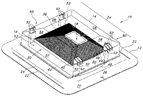
figures, like elements are given like reference numbers. Figure 1
shows a
vent 10 for venting a building enclosure according to an embodiment of the
present invention. The vent 10, which comprises a base 12 and a cover 14, is
attachable to an external surface of the building enclosure, typically a roof
(not
shown), over a vent opening in the roof.
The base 12 includes a vent structure 16, including an aperture 18 (best
seen in Figure 3) therein to permit gas to pass in to and out of the building
enclosure through the vent opening. Accordingly, the base 12 preferably also
includes an attachment element for attaching the base 12 to the roof such that
the aperture 18 is in fluid communication with the opening in the roof
material.
In the preferred embodiment the attachment element comprises an outer flange
20 extending away from the aperture 18. The outer flange 20 may be secured
to the roof in any convenient manner, including using clips, nails or screws.
Furthermore, it will be appreciated that the outer flange 20 is sized and
shaped
so as to allow shingles to be lapped over the flange 20 during installation,
in a
manner that prevents water from leaking under the shingles and onto the roof
material below. In this way, the flange 20 functions similarly to a shingle on
a
sloped roof. Since the portion of the flange 20 disposed downward along the
sloped roof is lapped over the shingles, during periods of rain, the water is
discharged off of the flange 20 onto the shingles disposed downwardly of the
flange 20, thus preventing water from entering underneath the shingles.
CA 02597366 2014-11-17
=
-13-
However, particularly in conditions of heavy rain, it is preferred to prevent
the rain falling onto the outer flange 20 from working its way under shingles
which are lapped over the outer flange 20 along the side of the vent 10. This
is accomplished in part providing the flange 20 with a rain ridge 22 along
both
sides, as shown in Figures 1 and 6. The purpose of the rain ridge 22 is to
direct
the water toward the portion of the vent 10 disposed downwardly along the
sloped roof. Since the downwardly-disposed portion of the flange 20 is lapped
over the shingles, the water is discharged off of the flange 20 on top of the
shingles, thus preventing water from entering underneath the shingles.
Preferably, the base 12 comprises at least two sides 24 to face sideways
along a sloped roof. The base 12 also preferably includes at least one non-
side
portion 26. Most preferably, the base 12 comprises a vent structure 16
including an aperture-surrounding wall 30, itself comprising vent structure
walls
32, two of said vent structure walls 32 facing sideways along the sloped roof
and functioning as the sides 24 of the base 12. Preferably, the at least one
non-side portion 26 comprises a third vent structure wall 32 facing upward
along
the sloped roof, and a fourth vent structure wall 32 facing downward along the
sloped roof.
In the preferred vent structure 16, the vent structure walls 32 surround
the aperture 18 through the base 12 that permits gas to flow through the vent
10. A screen 38, configured to permit gas flow therethrough, is preferably
associated with the vent structure 16 and aperture 18, and positioned to
prevent
unwanted material (e.g. rodents, refuse) to enter the aperture 18 from
outside.
It is preferable that the aperture 18 be positioned within the aperture-
surrounding wall 30, so that a top end 40 of the aperture-surrounding wall 30
will be spaced vertically from the roof when the vent 10 is installed thereon.
As
a result, the aperture-surrounding wall 30 presents a barrier to water flowing
along the roof and prevents the water from entering the aperture and into the
building enclosure. Instead, water flowing along the roof is simply deflected
off
of the aperture-surrounding wall 30, and flows away from the vent 10. It will
CA 02597366 2014-11-17
=
-14-
further be appreciated that spacing the top end 40 of the aperture-surrounding
wall 30 from the roof reduces the probability that rain will bounce off of the
roof,
under the cover 14 and through the aperture 18 into the building enclosure.
This is because the top end 40 of the aperture-surrounding wall 30 presents a
barrier to bouncing raindrops, reducing the risk that they will enter the
aperture
18.
In the embodiment shown in Figure 6, the screen 38 is substantially (but,
not necessarily perfectly) rectangular in plan view, and has four screen
sections
42 corresponding to each side of the rectangle (i.e. up, down, two sides). In
embodiments where the screen 38 has a different shape in plan view, the
screen 38 would typically have a screen section corresponding to each side of
the shape. Although it is contemplated that the screen 38 may be omitted in
certain embodiments of the present invention, it will be appreciated that if a
screen 38 is present, it can have one or more screen sections 42.
The screen 38 is preferably formed of vertical screen members 44 which
provide relatively small spaces 46 between the screen members 44. These
spaces 46 are sized such that unwanted objects such as birds, animals or
debris are prevented from entering the aperture 18, whereas air, water vapour
or gas can flow through the spaces 46 between the screen members 44. It will
be appreciated by those skilled in the art that the presence of the screen
members 44 has the effect of reducing the available air flow area through the
aperture, as air can only flow through the spaces 46 between those screen
members 44. To compensate for this, it is preferred to increase the surface
area of the screen 38 to enhance air flow. One way of increasing surface area
of the screen 38 is to form the screen 38 in the shape of a pyramid which
extends upwardly from the top 40 of the aperture-surrounding wall 30, as best
seen in the Figure 1.
It can now be appreciated by those skilled in the art that the aperture-
surrounding wall 30 also acts as a screen spacer. That is, it spaces the
screen
38 vertically away from the flange 20 and the roof. When the vent 10 is
CA 02597366 2014-11-17
=
=
-15-
positioned on an intermediate portion of a sloped roof (i.e. between the roof
ridge or apex and the roof edge), spacing the screen 38 away from the roof
helps to prevent flowing water or rain from entering under the cover 14 and
leaking through the aperture 18.
Preferably, the vent structure 16 also includes a liquid deflector 48 for
use in situations where the vent 10 is mounted on sloped roofs. As best seen
in Figures 1 and 6, the liquid deflector 48 is positioned at the upward
portion of
the aperture-surrounding wall 30. The liquid deflector 48 preferably has a
smoothly curved shape which serves two functions. First, the smoothly curved
continuous shape of the liquid deflector 48 facilitates the cutting of
shingles to
match its shape, by permitting a single continuous cut, as opposed to the two
or more cuts required with prior art liquid deflectors, such as, for example,
those
formed from two surfaces meeting at a peak or edge. This prevents damaging
overcuts in shingles during installation, and reduces the risk of future
leaks.
Second, the liquid deflector 48 provides additional protection against liquid,
such as rain, flowing down the sloped roof from entering the vent structure
16,
by guiding the liquid to the sides of the aperture-surrounding wall 30. Thus,
the
preferred vent 10 will be used on sloped roofs and will be installed with the
liquid deflector 48, positioned on the upward vent structure wall 32, facing
up
the slope. It will be appreciated by those skilled in the art that the
invention
comprehends vents 10 in which the vent structure 16 does not include the
liquid
deflector 48 described above.
As shown in Figure 1, the cover 14 is mountable to the base 12 so as to
cover 14 the aperture 18 to prevent rain from entering, while permitting gas
flow
through the aperture 18. In the preferred embodiment as shown in Figure 1, the
cover 14 is spaced from the screen 38, flange 20 and aperture 18 to permit gas
flow. Other configurations that block rain from entering the aperture 18, and
permit gas flow are also comprehended by the invention.
Referring to Figure 1, the preferred mode of attachment involves using
an attachment means in the form of four attachment structures. Each
CA 02597366 2014-11-17
=
-16-
attachment structure (see Figure 1) comprises a first attachment member in the
form of a shaft 50 extending from the underside of the cover 14 which
registers
with a second attachment member in the form of a receptacle 52 extending
from the base 12 (see Figure 2). As best seen in Figure 4, the free end of the
shaft 50 includes an attachment head 54 which preferably is generally in the
shape of an arrow head. The embodiment of Figure 4 shows a sagittate
member having a first thick end and an opposed thinner or apical end with a
tapered or chevron-shaped edge therebetween. At the free end of the
receptacle 52 is an opening 56 (best seen in Figure 6), which is configured to
register with the corresponding attachment head 54. In operation, the cover 14
is attached to the base 12 by registering each attachment head 54 with the
corresponding opening 56. The opening 56 of each receptacle 52 flexes open
to admit the matching attachment head 54. Once the head 54 has been
inserted beyond the opening 56, the opening 56, preferably having a shape
memory, returns to its pre-flexed size and shape and closes around the head
54. Thus, the opening 56 catches the head 54 at its upper end and is adapted
to grip the head 54 to prevent it from being withdrawn from the receptacle 52.
As best seen in Figure 1, the result is that each shaft 50 and corresponding
receptacle 52 lock together to form unitary pillars which hold and support the
cover 14 at a predetermined position above the base 12. In the preferred
embodiment, the attachment heads 54 are sized and shaped to cover
substantially the entire width of the openings 56, so as to prevent rain water
from leaking into the receptacles 52, and working its way into the aperture
18.
It will be appreciated that the attachment means and attachment
structure(s) could take any appropriate form. What is important is that the
vent
10 include one or more attachment structures to attach the cover 14 to the
base
12 so that precipitation is blocked from entering the aperture 18 and gas flow
through the aperture18 is permitted.
As shown in Figures 2, 4, and 5, the shafts 50 and receptacles 52 are
preferably integrally moulded to the underside of the cover 14 and base 12 in
CA 02597366 2014-11-17
-17-
matching relation. As best seen in Figure 4, the cover 14 has a first cover
portion 58 and a second cover portion 60, the first and second cover portions
being angled relative to one another. In the preferred embodiment shown in
Figure 4, the first cover portion 58 corresponds to a top portion of the cover
14,
while the second cover portion 60 corresponds to a side portion of the cover
14.
In the most preferred embodiment, the second portion 60 is sized, shaped and
positioned to be oriented substantially perpendicularly to the roof. The
shafts
50 are carried by both the first and second cover portions 58,60 on the
underside of the cover 14, and the receptacles 52 are attached to the base 12
(see Figures 2 and 5). As mentioned above, in prior art vents, discolourations
often occur on vent covers where the shafts are connected to the covers, as a
result of the vents being stacked and the shafts bearing the weight of
multiple
vents. It has been discovered that, by attaching the shafts 50 to at least two
cover portions which are angled relative to one another, such discolourations
on the top surfaces of the covers are reduced or eliminated. Without being
bound to any particular theory, it is believed that by attaching the shafts 50
to
at least two cover portions which are angled relative to one another, the
stress
load from the weight of the stacked vents, on the point of connection of the
shaft's attachment to the cover 14 of vents lower in the stack, is evenly
distributed over a broader area of the cover 14, providing a sturdier
construction, which is less resistant to discolouration due to the stress
load. In
addition, in the preferred embodiment, some of the weight borne by the shaft
50 is borne at the point of connection between the shaft 50 and the side
portion
of the cover 14, so that there is shear stress (not normal stress) created on
the
side portion. It appears that shear stress is less likely to create the
problematic
discolouration.
It will be appreciated that cover portions 58 and 60 can be angled relative
to one another in a variety of ways. For example, in the embodiment of Figures
1 and 2, the portions 58 and 60 are each substantially planar sections that
meet
at one or more edges. However, portions 58 and 60 need not intersect to be
CA 02597366 2014-11-17
=
-18-
angled relative to one another. Furthermore, portions 58 and 60 need not be
planar to be angled relative to one another in accordance with the present
invention. Rather, portions 58 and 60 could be arcuate sections of a curved
cover, as shown, for example, in Figure 8. In the alternate embodiment of
Figure 8, portions 58 and 60 are themselves curved. Line 59 shows the
approximate angle of portion 58, while line 61 shows the approximate angle of
portion 60. Lines 59 and 61 are, in this example, tangents to the curved cover
14 at the mid-point of portion 58 and portion 60 respectively. The angle
between lines 59 and 61 illustrates that portions 58 and 60 are substantially
angled relative to one another. Thus, because portions 58 and 60 are
positioned at different locations along curved cover 14, they are angled
relative
to one another as shown by lines 59 and 60.
As shown in Figures 1 and 4, each shaft 50 is attached to the first and
second cover portions 58,60 by web members 62. Although three such web
members 62 are shown in the figures, it is contemplated that more or fewer web
members 62 may be employed, as long as the shaft 50 is carried by the at least
two cover portions 58,60. Furthermore, the web members 62 may be made
thicker according to design requirements which will be appreciated by those
skilled in the art.
It will also be appreciated by those skilled in the art that the invention
comprehends other attachment means not comprising the specific structure
described above. What is important in this aspect of the invention is that the
attachment means is carried by both the first and second cover portions 58,60,
and secures the cover 14 to the base 12 while permitting the flow of gas
through the aperture 18 and between the building enclosure and the outside.
For example, the shafts 50 and receptacles 52 could be glued, screwed or heat-
staked together. Also, other locking mechanisms besides the above-described
openings 56 and arrowhead 50 shafts could be used. Similarly, it would be
possible to use a different number of attachment structures, heads 54 or
shafts
50. What is important is that the base 12 and the cover 14 are adequately
CA 02597366 2014-11-17
,
=
=
-19-
secured to one another. Also, the attachment means should be carried by at
least two cover portions 58,60 which are angled relative to one another, and
should secure the cover 14 to the base 12 while permitting the free flow of
gas
through the aperture 18 and between the building enclosure and the outside.
Referring now to Figure 6, the base 12 of the vent 10 according to an
embodiment of the present invention is shown in plan view. It has been found
that by positioning the attachment structures at the non-side portion 26 of
the
base, the sides 24 are left clear so that overlapping of shingles at the sides
is
not interfered with. If the attachment structures were positioned at the side
24,
they would create a jagged profile with wall 30 that would make it harder to
cut
shingles to overlap the flange 20 so that the shingles abut the aperture-
surrounding wall 30. By contrast, with the attachment structures positioned at
the non-side portion 26, a smooth profile can be presented on the sides 24,
facilitating the cutting of the shingles, and the positioning of the shingles
so that
they abut the aperture-surrounding wall 30. With a smooth profile, the roofer
does not need to make cut-outs in the shingle to match the attachment
structures when laying the shingles up against the sides 24.
As mentioned above, the base preferably includes four attachment
receptacles 52, two of which are positioned at the upward end of the base 12
and the other two are positioned at the downward end. The attachment
receptacles 52 may be formed integrally into the aperture-surrounding wall 30
of the vent structure 16, into the flange 20 apart from the vent structure 16,
or
any combination thereof.
Preferably, the vent structure 16 has a width W that is approximately the
same width as a standard shingle tab - about 20.3 centimetres. In this way,
once one shingle tab is cut out, the vent 10 will fit neatly between the
remaining
shingle tabs, resulting in a clean looking installation. No cutting off of
portions
of tabs is required.
Referring now to Figures 7A and 7B, louvres 64 removably attachable
to the vent structure 16 at the top end 40 of the aperture-surrounding wall 30
CA 02597366 2014-11-17
=
=
-20-
are shown. The louvres 64 are preferably attached by way of friction fit
coupling
of a portion of the louver 64 to a complementary portion of the vent structure
16. Other ways of attaching the louvres 64 to the vent structure are
comprehended, as is a vent 10 without louvres 64. What is preferred is that
louvres 64 are sized, shaped and positioned to some or all of the
precipitation
that has fallen under the cover 14 from bouncing up into the aperture 18. In
periods of heavy rain, rain drops will hit the shingles and bounce upwards. In
some circumstances the rain drops may fall under the cover 14 and bounce up
into the aperture 18. The preferred louvres 64 function to block the bouncing
rain drops from reaching the aperture 18. Preferably, the louvres 64 also
block
snow from blowing into the aperture18. Therefore, most preferably, the louvers
64 are attached to the vent structure 16 so as to extend outwardly, and
downwardly towards the flange 20 at an angle of about 45 degrees.
While reference has been made to various preferred embodiments of the
invention other variations are comprehended by the broad scope of the
appended claims. Some of these have been discussed in detail in this
specification and others will be apparent to those skilled in the art. All
such
variations and alterations are comprehended by this specification are intended
to be covered, without limitation.