Note : Les descriptions sont présentées dans la langue officielle dans laquelle elles ont été soumises.
CA 02605584 2007-10-19
1
TITLE
HANDLING COMPRESSIBLE MATERIALS
TECHNICAL FIELD
The present disclosure relates to a method, apparatus, and attachment for
handling
compressible materials, such as trash.
BACKGROUND ART
One method of handling compressible materials, such as trash, is to collect
the material
and hold it in a transfer station where it is highly compressed into a charge
and then
bound by encircling wire. The bound charge is then transported to a remote,
long-term
or permanent storage location.
As cities have grown, the need to have permanent refuse or trash depositories
farther
away from city boundaries has increased, and it has become impractical to use
a
vehicle designed to collect trash from primary sources, such as rubbish
containers or
bins, to take that trash to a remote permanent location.
The answer has been to have dedicated trash collection vehicles, which
conventionally
include some modest compression to assist in storage capacity for each
vehicle,
transfer their respective loads to a transfer station that is much closer to
the city.
Thereafter, the trash is transferred in bulk to a permanent location.
CA 02605584 2007-10-19
2
Currently, trash is very highly compressed at transfer stations and then held
while it is
encircled with wire, thereby forming a bale. These bales are then stacked one
upon the
other on the tray of a truck and transferred to the permanent depository.
A number of problems reside in this process. First of all, because the
encircling wire
does not separate the trash from the atmosphere, offensive odors may attract
birds or
rodents.
Next, because the wire is often tightly wound around the compressed materials,
it can
have, depending on the nature of the materials, a tendency to cut into and
indeed
through the materials, thus reducing the compression and releasing some of the
bound
material. Extra coverings on the transport vehicies are often needed to reduce
these
effects.
The term trash as used throughout this specification rnay include waste that
is collected
by city authorities that can be compressed and then held together by
encircling wire,
tapes, or the like for subsequent transport and storage. However, the present
disclosure may be applicable to any type of compressible or fibrous materials
that are
traditionally compressed and baled for transport, such as hay or green fodder.
A further difficulty is that the wire-encircled trash will return to a
generally cylindrical
shape as it expands. This may occur even if it was compressed to be of
rectilinear
proportions when it was bound. Bales that revert to a cylindrical shape become
CA 02605584 2007-10-19
3
unstable when stacked one upon the other. This means that storage efficiency
also
becomes a problem.
Other objects and advantages of the present invention will become apparent
from the
following description, taken in connection with the accompanying drawings,
wherein, by
way of illustration and example, an embodiment of the present invention is
disclosed.
SUMMARY OF THE INVENTION
One aspect of the present disclosure includes a method of handling
compressible
materials, the method incuding the steps of compressing a first charge of
compressible
material into a first compressed charge in a compression area; pushing the
first
compressed charge from the compression area into a holding area, the holding
area
being substantially the same size as the first compressed charge; compressing
a
second charge of compressible material in the cornpression area to form a
second
compressed charge; and pushing the second compressed charge from the
compression
area into the holding area, thereby ejecting the first charge from the holding
area into a
bag configured to receive the first compressed charge.
Another aspect of the present disclosure includes an apparatus for handling
compressible materials including compressing means adapted to compress a first
charge of compressible material into a first compressed charge in a
compression area;
a holding area which is substantially the same size as the first compressed
charge; and
push means adapted to push the first compressed charge from the compression
area
CA 02605584 2007-10-19
4
into the holding area; wherein the compression means is adapted to compress a
second
charge of compressible material in the compression area to form a second
compressed
charge; and wherein the push means is adapted to push the second compressed
charge from the compression area into the holding area, such that it wil eject
the first
compressed charge from the holding area into a bag configured to receive the
first
compressed charge.
Yet another aspect of the present disclosure includes an attachment for a
baling
machine including a holding area configured to receive a first compressed
charge
ejected from a compression area of the baling machine, the holding area being
substantially the same size as the first compressed charge; wherein the
holding area is
configured to retain the first compressed charge until a second compressed
charge is
forced from the compression area into the holding area and ejects the first
compressed
charge from the holding area into a bag that is configured to receive the
first
compressed charge.
In this respect, before explaining at least one embodiment of the invention in
detail, it is
to be understood that the invention is not limited in its application to the
details of
construction and to the arrangements of the components set forth in the
following
description or illustrated in the drawing. The invention is capable of
embodiments in
addition to those described and of being practiced and carried out in various
ways.
Also, it is to be understood that the phraseology and terminology employed
herein, as
CA 02605584 2007-10-19
well as the abstract, are for the purpose of description and should not be
regarded as
limiting.
The accompanying drawings, which are incorporated in and constitute a part of
this
specification, illustrate certain embodiments of the invention, and together
with the
description, serve to explain the principles of the invention.
Those skilled in the art wiII appreciate that the conception upon which this
disclosure is
based may readily be utzed as a basis for designing other structures, methods,
and
systems for carrying out the several purposes of the present invention. It is
important,
therefore, to recognize that the claims should be regarded as including such
equivalent
constructions insofar as they do not depart from the spirit and scope of the
present
invention.
BRIEF DESCRPT/ON OF THE DRAWINGS
For a better understanding of this disclosure it will now be described with
respect to an
exemplary embodiment which shall be described herein with the assistance of
drawings
wherein:
Figures 1 and 2 are overall perspective views of an exemplary apparatus for
forming
and handling compressible material bales;
Figure 3 is a perspective view of an exemplary mechanical robot that is
supporting an
exemplary bag support frame;
CA 02605584 2013-08-29
6
Figures 4 and 5 are detailed views of an exemplary bag support frame passing
over a
sleeve or nozzle defining a trash holding area;
Figures 6 through 10 are schematic illustrations of the exemplary trash bale
forming
equipment, and successive stages in an exemplary method of the formation of a
bale;
Figure 11 is a perspective view of a trash bale formed by the exemplary
apparatus and
method of Figures 1-10; and
Figures 12 and 13 are schematic illustrations of an exemplary apparatus for
forming and
handling compressible material bales according to a further embodiment of the
invention, in which a closure gate is used to close the compression area.
DETAILED DESCRIPTION OF THE INVENTION
Referring now to Figure 1, an exemplary embodiment of an apparatus for
handling
compressible materials is illustrated. Specifically, Figure 1 illustrates a
trash
compressing system 1, a trash conveyor housing 2 for a trash conveyor (not
shown)
that supplies trash to the trash compressing system 1, a holding area 4 for a
compressed charge of trash, a programmable robot 6, and an overhead conveyor 8
supporting a number of bag support frames 10.
Shown in greater detail in Figure 2 are the holding area 4 for the compressed
charges,
the programmable robot 6, the overhead conveyor 8 supporting a number of bag
support frames 10, and a bag support frame loading station 12. The trash
compressing
system 1 and the trash conveyor housing 2, have been omitted from this view in
CA 02605584 2007-10-19
7
order to perrnit better visibility of the aforementioned components. The
operation and
interaction of all of this equipment may be managed by a programmable control
system.
The bag support frames 4.0 may be adapted to support fresh bale bags 14, and
travel
on the overhead conveyor 8. Th,is conveyor may be routed from the bag support
frame
loading station 12, to a support frame holding station 13. It is from this
support frame
holding station 13 that the programmable robot 6 may take the loaded bag
support
frames 10 as desired. Once a bag support frame 10 has been used, (i.e. it no
longer
supports a bale bag 14), it may be returned to the overhead conveyor 8 by the
programmable robot 6 and taken back to the bag support frame loading station
12 for
recharging with a fresh bale bag 14.
The bale bags 14 may be made from a strong, woven plastic material. When
opened to
their full extent, the bale bags 14 may be shaped so as to define a
substantially
rectangular cube (or any other substantially rectilinear shape). In one
embodiment,
each bale bag 14 may include a first rectilinear end, sides emanating from the
end, and,
at an opposite end, an edge which includes a seam configured to accept any
type of
closure means. For example, the seam may incorporate a closable opening
defined by
a 'drawstring' type of arrangement (as seen in Figure 11), although a cable or
tape may
be used in place of string due to its increased strength.
Referring now to Figure 3, the bag support frames 10 may be comprised of four
frame
elements that define a rectangular opening 16 that is surrounded by a short
sleeve or
nozzle 15 (shown in Figure 4). The bag support frames 10 may be equipped with
a pair
CA 02605584 2007-10-19
8
of cam-locks 18 on the top 20 and bottom 22 frame elements, which are adapted
to
retain the bale bag 14, once the opening in the bag has been passed over the
short
sleeve or nozzle 15.
The programmable robot 6 may be equipped with ar end effector 24 that is
adapted to
engage a receiving pordor 26 of said end effector 24 on the side of the bag
support
frame 1 O. The top 20 of the bag support frame 10 may then be equipped with
loop
means 17 that allowlt to be suspended from hooks on the overhead conveyor 8
when
the bag support frame 1C is not in use.
At the commencement of a baling cycle, the programmable robot 6 may remove a
loaded bag support frame 10 from the bag support frame holding station 13 of
the
overhead conveyor 8, and position the opening 16 of the bag support frame 10
and the
bale bag 14 over an end of a rectilinear sleeve or nozzle 30 defining the
holding area 4.
This holding area 4 rria.'y be substantially the same size as the compressed
charges it is
adapted to receive, and may hold compressed charges therein in a substantially
similar
rectilinear shape. The holding area 4 may also include a pair of opposed sides
and an
opposed top and bottom defining a passageway aligned to receive a compressed
charge and maintain a compressed charge in a compressed state. The holding
area 4
may also include an outer surface adapted to receive a bag around it, such
that the bag
may be configured to accept a compressed charge ejected from the holding area
when
the bag is drawn around the outer surface. The advantages of sizing the
holding area 4
are that it retains thc,, compressed material in its compressed state, and it
improves
CA 02605584 2007-10-19
9
dimensional control of both the charge and the completed bale, thereby
ensuring that
the compressed charge has a smooth transition from the holding area 4 into the
be
bag 14. In one embodiment, the holding area 4 may be made from steel.
in one embodiment, a jet of compressed air may be supplied via passageways
passing
through the walls of the sleeve or nozzle 30 so as to give shape to the bale
bag 14 as
the programmable robot 6 passes it over the sleeve or nozzle 30.
Referring now to Figures 4 and 5, the programmable robot 6 may continue
passing the
bale bag 14 over the sleeve or nozzle 30 until it reaches a programmed end
position. At
a point near the end of travel, there may be a small pair of brackets 32 fixed
to the
sleeve or nozzle 30, which are configured to engage arid release the pair of
cam-locks
18 retaining the bale bag 14 to the bag support frame 10, upon being urged
against
these brackets 32 by the movement of the programmable robot 6 relative to the
sleeve
or nozzle 30. The robot 6 may continue to move the bag support frame 10 along
the
sleeve or nozzle 30 until The opening in the bale bag 14 falls off of the
short sleeve or
nozzle 15 on the bag support frame 10 and the bag support frame 10 is free of
the bale
bag 14. The programmable robot 6 rnay then withdraw the now empty bag support
frame 10 from the sleeve or nozzle 30, leaving the bale bag 14 disposed upon
the
sleeve or nozzle 30.
The programmable robot 6 may return the empty bale support frame 10 to the
overhead
conveyor 8 and hang the empty bag support frame 10 on the overhead conveyor 8.
The end effector 24 may then release the empty bag support frame 10. The
CA 02605584 2013-08-29
programmable robot 6 may then move to the support frame holding area 13,
engage a
loaded bag support frame 10 using the end effector 24, and become ready to
begin the
process again.
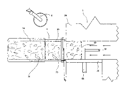
Referring now to Figures 6 through 10, the compressible material handling
equipment
may define a compression area 50. Compressible material may be delivered to
the
compression area 50 on a conveyor (not shown). At the end of the conveyor (not
shown), the compressible material may fall from the conveyor (not shown) and
into a
hopper (not shown) that feeds the trash into the compression area 50.
Referring now to Figure 6, the compression area 50 may be defined by a flat
floor
surface 52 (not visible), a first upright side wall 54 that is fixed in
position relative to the
flat floor surface 52, a second upright side wall 56 that faces the first
upright side wall 54
and is fixed to the end of a first hydraulic ram 58, and a first upright end
wall 60 that is
fixed to the end of a second hydraulic ram 62.
At the moment a charge of compressible material is dropped into the
compression area
50 from the conveyor (not shown), each of the first and second hydraulic rams
58 and
62 may be in a retracted position.
At the conclusion of a working day or shift, as the case may be, the last
compressed
charge may be left in the holding area 4, (i.e. in the sleeve or nozzle 30
defining the
holding area). This way, the first charge compressed on the next day or shift
is not
compressed without some means of constraining that one end of the charge
during the
CA 02605584 2007-10-19
11
compression operation. Specifically, it may be constrained by an end of the
last
compressed charge of the previous shift.
At the commencement o a new shift, the equipment may be activated, and the
first
hydraulic ram 58 may drive the second upright sidewall 56 towards the fixed
upright
sidewall 54 compressing a charge of compressible material 72. The second
hydraulic
ram 62 may remain stationary in its retracted position, where it supports the
first upright
end wall 60 during compression. The first hydraulic ram 58 may continue
compressing
the material until a compressing surface 74 of the first upright side wall 56
is coplanar
with an inner surface 76 of the sleeve or nozzle 30 defining the holding area
4, as
shown in Figure 7, at which point the first hydraulic ram 58 may stop in a
temporarily
locked position.
The second hydraulic ram 62 may then drive the first upright end wall 60 so as
to push
the freshly compressed charge of compressible material 72 from the compression
area
50 into the holding area 4, as shown in Figures 8 and 9, which has the effect
of
displacing a first, previously compressed charge of compressible material TO
(that is in
the sleeve or nozzle 30 defining the holding area 4) from the holding area 4
into the be
bag 14. As the first charge of compressible material 70 leaves the sleeve or
nozzle 30 it
may pick up the end of the bale bag 14 and draw the bale bag 14 with it until
both the
bale bag 14 and first charge of compressible material 70 are free of the
sleeve or nozzle
30. hi one ernbodiment, the second hydraulic ram 72 may push in a direction
transverse to the direction in which the first hydraulic ram 58 compresses.
CA 02605584 2007-10-19
12
An advantage of the holding area 4 is that the compressible material is given
an
opportunity to settle and stabilize in the holding area prior to its ejection
into the bale
bag 14. A further advantage is that it allows a second charge of compressed
material to
be used to force the first charge of compressed material from the holding area
4 into the
bale bag 14, rather than using a hydraulic cylinder with an unnecessarily long
stroke to
effect this ejection. Moreover, as discussed above, an end of the first
compressed
charge may act as a closure to an ejection end of the compression area 50
during
compression of the second compressed charge.
Referring now to Figure 10, once a freshly formed rectilinear bale 80
containing its
charge of compressed material is free of the sleeve or nozzle 30, a
'drawstring' style
opening 82 (Figure 11) in the end of the bale bag 84 can be closed and tied
off by the
programmable robot 6 or a person.
The rectilinear bales 80 can then be safety stacked for transporting and
storage, and
the bale bag 14 may reduce the likelihood that the bale will lose this
rectilinear shape
once stacked.
The two hydraulic rams 58 and 62 may then return to their home positions, and
the
cornpression area 50 may be ready to accept a fresh charge of compressible
material.
in one embodiment, when traveiing on the overhead conveyor 8, each bag support
frame 10 may be oriented such that its open face faces in the direction of
conveyor
travel. As a used bag support frame 10 approaches the loading station 12 it
may be
CA 02605584 2007-10-19
=
13
rotated 90 degrees to the direction of travel of the conveyor. When the bag
support
frame 10 is in the loading position a guide block 90 may then be automatically
inserted
into the opening 16 in the bag support frame 10 and a pair of operators, one
standing to
each side of the support frame 10 and guide block 90, rnay feed a new bale bag
14 onto
the guide block 90 and secure it to the bag support frame 10 (and the short
sleeve or
nozzle 15) using the pair of cam-locks 18. The guide block 90 may then be
withdrawn
and the bag support frame 10 may be rotated back so that its open face faces
in the
direction of conveyor travel once again.
Referring now to Figures 12 and 13, where there is illustrated an embodiment
further
including a closure for the compression area 50, a closure, such as a gate
100, may be
positioned and maintained across an ejection end of the compression area 50
while a
compression stroke is occurring. Once the compression stroke is finished, the
gate 100
may be withdrawn and the ejection stroke effected using the second hydraulic
ram 62
as described above.
Automating the bale forming process in the manner described offers the
following
further advantages. Bales created using this method may have a density upwards
of
100 kg per cubic meter more than conventionally strapped bales. The need for a
strapper or wire tie machine may be eliminated. Bales can be produced at a
higher
rate, as the production rate is not dictated by the strapping machine used to
create
conventional bales. The working environment may be improved as material cannot
fall
out of the bale bags as it can fall cff of a wire tied bale. Finally, it may
reduce the
CA 02605584 2007-10-19
14
number of people required to work in this otherwise dangerous and unpleasant
environment.
it would be understood by a person skilled in the relevant art however, that
the process
could be adapted such that the tasks of the programmable robot (i.e., loading
of the
bale bag on the nozzle defining the holding area) could be safely carried out
by one or
more people.
Although the invention has been herein shown and descnbed in what is conceived
to be
the most practical and preferred embodiment, it is recognized that departures
can be
made within the scope of the invention, which is not to be limited to the
details
described herein but is to be accorded the full scope of the appended claims
so as to
embrace any and all equivalent devices and apparatus.