Note : Les descriptions sont présentées dans la langue officielle dans laquelle elles ont été soumises.
CA 02606435 2007-10-11
165598
CANTILEVERED NOZZLE WITH CROWNED FLANGE TO IMPROVE
OUTER BAND LOW CYCLE FATIGUE
BACKGROUND OF THE INVENTION
This invention relates generally to improving the durability of gas turbine
engine components and, particularly, in reducing the thermal stresses in the
turbine
engine stator components such as nozzle segments.
In a typical gas turbine engine, air is compressed in a compressor and mixed
with fuel and ignited in a combustor for generating hot combustion gases. The
gases
flow downstream through a high pressure turbine (HPT) having one or more
stages
including one or more HPT turbine nozzles and rows of HPT rotor blades. The
gases
then flow to a low pressure turbine (LPT) which typically includes multi-
stages with
respective LPT turbine nozzles and LPT rotor blades. The HPT and LPT turbine
nozzles include a plurality of circumferentially spaced apart stationary
nozzle vanes
located radially between outer and inner bands. Typically, each nozzle vane is
a
hollow airfoil through which cooling air is passed through. Cooling air for
each vane
can be fed through a single spoolie located radially outwardly of the outer
band of the
nozzle. In some vanes subjected to higher temperatures, such as the HPT vanes
for
example, an impingement baffle may be inserted in each hollow airfoil to
supply
cooling air to the airfoil.
The turbine rotor stage includes a plurality of circumferentially spaced apart
rotor blades extending radially outwardly from a rotor disk which carries
torque
developed during operation. Turbine nozzles, located axially forward of a
turbine
rotor stage, are typically formed in arcuate segments. Each nozzle segment has
two or
more hollow vanes joined between an outer band segment and an inner band
segment.
Each nozzle segment and shroud hanger segment is typically supported at its
radially
outer end by flanges attached to an annular outer casing. Each vane has a
cooled
hollow airfoil disposed between radially inner and outer band panels which
form the
-1-
CA 02606435 2007-10-11
165598
inner and outer bands. In some designs the airfoil, inner and outer band
portions,
flange portion, and intake duct are cast together such that the vane is a
single casting.
In some other designs, the vane airfoils are inserted in corresponding
openings in the
outer band and the inner band and brazed along interfaces to form the nozzle
segment.
Certain two-stage turbines have a cantilevered second stage nozzle mounted
and cantilevered from the outer band. There is little or no access between
first and
second stage rotor disks to secure the segment at the inner band. Typical
second stage
nozzles are configured with multiple airfoil or vane segments. Two vane
designs,
referred to as doublets, are a very common design. Three vane designs,
referred to as
Triplets are also used in some gas turbine engines. Doublets and Triplets
offer
performance advantages in reducing split-line leakage flow between vane
segments.
However, the longer chord length of the outer band and mounting structure
compromises the durability of the multiple vane segment nozzles. The longer
chord
length causes an increase of chording stresses due to the temperature gradient
through
the band and increased non-uniformity of airfoil and band stresses, such as
for
example, shown in FIG.6 for a conventional outer band. The increased thermal
stress
may reduce the durability of an outer band and the turbine vane segment. It is
desirable to have a flange design for supporting turbine engine components
such as the
turbine nozzle segments that avoid reduction in the durability of multiple
vane
segments due to longer chord length of the outer band and mounting structure.
It is
also desirable to have turbine nozzle segments that avoid increase of chording
stresses
due to temperature gradient through the outer band and increased non-
uniformity of
airfoil stresses due to longer chord length of the multiple vane segments. It
is also
desirable to have turbine nozzle segments that avoid increase of stresses near
the
middle vane of a Triplet or other multiple vane segments which limits the life
of the
segment.
BRIEF DESCRIPTION OF THE INVENTION
A flange for supporting arcuate components comprising at least one arcuate
rail, each arcuate rail having an inner radius, a first taper location, a
first taper region,
a second taper location, a second taper region, wherein the thickness of at
least a
-2-
CA 02606435 2014-03-20
= 165598
portion of the first taper region is tapered and wherein the thickness of at
least a
portion of the second taper region is tapered.
BRIEF DESCRIPTION OF THE DRAWINGS
The invention, in accordance with preferred and exemplary embodiments,
together with further objects and advantages thereof, is described in the
following
detailed description taken in conjunction with the accompanying drawings in
which:
FIG. 1 is a longitudinal cross-sectional view illustration of the assembly of
the turbine nozzle, shroud, shroud hangers and casing of a gas turbine engine.
FIG. 2 is a perspective view illustration of a nozzle segment shown in FIG. 1.
FIG. 3 is a perspective view illustration of the outer band of the nozzle
segment shown in FIG. 2 viewed axially aft-wardly at an angle to one side.
FIG. 4 is another perspective view illustration of the outer band of the
nozzle
segment shown in FIG. 2 viewed axially aft-wardly at an angle to another side.
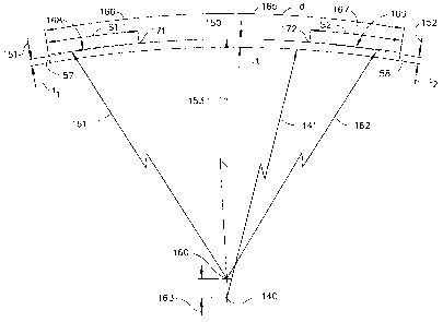
FIG. 5 is a schematic view illustration of an exemplary embodiment of a
crowned flange tapered thickness feature.
FIG. 6 is a perspective view illustration of a portion of a conventional
design
outer band of a conventional design nozzle segment showing stress contours
that can
occur in some designs.
FIG. 7 is a perspective view illustration of a portion of an outer band of an
exemplary embodiment of the present invention showing reduced stress contours.
FIG. 8 shows the relative stress gradients near maximum stress locations in a
conventional design outer band and an outer band with an exemplary embodiment
of
the present invention.
-3-
CA 02606435 2007-10-11
165598
DETAILED DESCRIPTION OF THE INVENTION
Referring to the drawings wherein identical reference numerals denote the
same elements throughout the various views, FIG. 1 a portion of turbine stage
10
comprising a Stage 1 turbine rotor 25, a Stage 2 turbine rotor 95 and a Stage
2 turbine
nozzle 40 located in between. Turbine blades 20 and 90 are circumferentially
arranged
around the rim of the Stage 1 and Stage 2 turbine rotors respectively.
As shown in FIG. 2 the turbine nozzle segment 40 comprises an inner band
80, and outer band 50 and vanes 45 that extend between the inner band and the
outer
band. The turbine nozzle segments 40 are usually have multi vane construction,
with
each nozzle segment comprising multiple vanes 45 attached to an inner band 80
and
an outer band 50. The nozzle segment 40 shown in FIG. 2 has three vanes 45 in
each
segment. The turbine nozzle vanes 45 are sometimes hollow, as shown in FIG. 2,
so
that cooling air can be circulated through the hollow airfoil. The turbine
nozzle
segments, when assembled in the engine, form an annular turbine nozzle
assembly,
with the inner and outer bands 80, 50 forming the annular flow path surface
through
which the hot gases pass and are directed by the airfoils to the following
turbine rotor
stage.
The nozzle segment including the outer band may be made of a single piece
of casting having the vane airfoils, the outer band and the inner band.
Alternatively the
nozzle segment may be made by joining, such as by brazing, individual sub-
components such as vanes foils, the outer band and the inner band. FIG. 4 and
FIG. 5
show such a sub-component, the outer band 50, which has airfoil cut-outs 65
wherein
the vane airfoil 45 can be inserted and joined by a suitable means such as
brazing.
The outer band 50 and inner band 80 of each nozzle segment 40 have an
arcuate shape so as to form an annular flow path surface when multiple nozzle
segments are assembled to form a complete turbine nozzle assembly. As shown in
FIG. 1, the outer band 50 comprises an outer band forward panel 55, a forward
flange
59 and an aft flange 56 located axially aft from the forward flange 59, that
are used to
provide radial support for the nozzle segment 40. The forward flange 59
comprises a
forward arcuate rail 51 which extends from a first end 57 to a second end 58
located at
-4-
CA 02606435 2007-10-11
165598
a circumferential distance from the first end 51, shown in FIGS. 3 and 4.
Similarly, the
aft flange 56 comprises an aft arcuate rail 53 which extends from the first
end 57 to
the second end 58 located at a circumferential distance from the first end 51.
At
assembly, the forward arcuate rail 51 engages with a clearance fit with an
arcuate
groove in the forward nozzle support 52 extending from a casing 70. The aft
arcuate
rail 53 is attached to the casing by means of C-clips engaging with a casing
aft flange.
An exemplary embodiment of the present invention to reduce the chording
stresses in arcuate components supported by arcuate flanges is shown in FIG.
5. The
arcuate component has an arcuate rail, such as for example the forward arcuate
rail 51
shown FIGS. 3 and 4 which provides support within a corresponding arcuate
groove
in another component , such as the forward nozzle support 52 shown in FIG. 1.
As
shown in FIG. 5, the arcuate rail has a constant inner radius 141 that is
continuous
between a first end 57 and a second end 58. Unlike conventional designs of
arcuate
support rails, the thickness of the arcuate rail in an exemplary embodiment of
the
present invention is varied between the first end 57 and the second end 58 so
as to
reduce the chording stresses in the arcuate components supported by the
arcuate rail.
In the exemplary embodiment shown in FIG. 5, the thickness of the arcuate rail
is
tapered in a first taper region 168 and a second taper region 169.
Specifically, the
arcuate rail thickness is tapered from a value "t" at a first taper location
171 to a value
"ti" 151 at the first end 57, and tapered from a value "t" at a second taper
location 172
to a value "t2" 152 at the second end 58. The variation of the thickness of
the arcuate
rail by means of tapering in selected regions allows the arcuate rail more
flexibility to
expand within the arcuate groove with which it engages during thermal
variations,
while maintaining the thickness in a middle region acts to prevent leakage of
hot gases
through the groove.
The taper in the first taper region 168 and the second taper region 169 can be
introduced in a variety of ways. For example, they may be introduced by
grinding a
flat surface on the outer portion on the taper regions 168 and 169. Another
exemplary
way of introducing the taper is by using first taper radius 161, a second
taper radius
162 and an outer radius 153 between the first taper location 171 and the
second taper
-5-
CA 02606435 2014-03-20
= 165598
location 172, as shown in FIG. 5. Any required thickness can be achieved by
selecting
a suitable offset between the rail inner center 140 and the rail outer center
160.
In the preferred embodiment of the design for an outer band of a nozzle
segment (FIGS. 3, 4), the first taper location 171 and the second taper
location 172 are
coincident at the mid-point on the outer surface of the arcuate rail. The
first taper
radius 161 and the second taper radius 162 are equal. For the outer band of
the nozzle
segment the forward arcuate rail 51 had an inner radius 141 of 12.596 inches,
an outer
radius 153 of 12.686 inches, a first taper radius 161 of 11.786 inches, a
second taper
radius 162 of 11.786 inches. The magnitude of the reduction in thickness of
the
arcuate rail varied from about 0.0000 inches at the middle to about 0.0135
inches at
the first end 57 and second end 58.
An example of the reduction in the stresses in an outer band of a turbine
nozzle segment as a result of the increased ability of the arcuate rails to
flex in the
presence of thermal gradients by the preferred embodiment described herein is
shown
in FIG. 7. The peak stresses in the outer band near the leading edge of the
mid vane is
reduced as compared to the results for a conventional design outer band shown
in
FIG. 6. The reduction of the stresses in the outer band resulting from the
implementation of the preferred embodiment of the present invention extend to
other
regions on the outer band also, as shown in the stress gradient plot shown in
FIG. 8.
The relative stress distribution 192 for the preferred embodiment in an outer
band is
significantly lower than the relative stress distribution 191 for a
conventional design
outer band.
While there have been described herein what are considered to be preferred
and exemplary embodiments of the present invention, other modifications of
these
embodiments falling within the scope of the invention described herein shall
be
apparent to those skilled in the art.
-6-