Note : Les descriptions sont présentées dans la langue officielle dans laquelle elles ont été soumises.
CA 02611336 2007-11-15
208379-3
ADVANCED BOOSTER SYSTEM
BACKGROUND OF THE INVENTION
This invention relates generally to gas turbine engines, and, more
specifically, to the compression modules therein, such as the booster and the
compressor.
In a turbofan aircraft gas turbine engine, air is pressurized in a fan module
and a compression module during operation. The air passing through the fan
module is
used for generating the bulk of the thrust needed for propelling an aircraft
in flight.
The air channeled through the compression module is mixed with fuel in a
combustor
and ignited, generating hot combustion gases which flow through turbine stages
that
extract energy therefrom for powering the fan and compressor rotors.
A typical compression module in a turbofan engine includes a multi stage
booster which compresses the air to an intermediate pressure and passes it to
a
multistage axial flow compressor which further pressurizes the air
sequentially to
produce high pressure air for combustion. Both the booster and the compressor
have
rotor stages and stator stages. The booster rotor is typically driven by a low
pressure
turbine and the compressor rotor is driven by a high pressure turbine.
Fundamental in booster and compressor design is efficiency in compressing
the air with sufficient stall margin over the entire flight envelope of
operation from
takeoff, cruise, and landing. However, compressor efficiency and stall margin
are
normally inversely related with increasing efficiency typically corresponding
with a
decrease in stall margin. The conflicting requirements of stall margin and
efficiency
are particularly demanding in high performance jet engines that require
increased
power extraction, while still requiring high a level of stall margin in
conjunction with
high compressor efficiency. In conventional designs, efficiency is usually
sacrificed in
order to achieve improved operability and increased stall margin.
-1-
CA 02611336 2007-11-15
208379-3
Operability of a compression system in a gas turbine engine is traditionally
represented on an operating map with inlet corrected flow rate along the X-
axis and
the pressure ratio on the Y-axis, such as for example, shown in FIG. 1 for a
booster. In
FIG. 1, operating line 102 and the stall line 101 are shown, along with
several constant
speed lines 104-108. Line 104 represents a lower speed line and line 105
represents a
higher speed line as compared to the design speed line 103. As the booster is
throttled
from the operating line 102 at a constant speed, such as the design speed
represented
by the constant speed line 103, the inlet corrected flow rate decreases while
the
pressure ratio increases, and the booster operation moves closer to the stall
line 101. In
order to avoid a stall, the fans, boosters and compressors in a gas turbine
engine are
designed to have sufficient stall margin with respect to the stall line, such
as line 101
shown in FIG. 1.
Maximizing efficiency of booster and compressor airfoils is primarily
effected by optimizing the velocity distributions over the pressure and
suction sides of
the airfoil. However, efficiency is typically limited in conventional booster
and
compressor designs by the requirement for a suitable stall margin. Any further
increase in efficiency results in a reduction in stall margin, and,
conversely, further
increase in stall margin results in decrease in efficiency.
High efficiency is typically obtained by minimizing the wetted surface area of
the airfoils for a given stage to correspondingly reduce airfoil drag. This is
typically
achieved by reducing airfoil solidity or the density of airfoils around the
circumference of a rotor disk, or by increasing airfoil aspect ratio of the
chord to span
lengths.
For a given rotor speed, this increase in efficiency reduces stall margin. To
achieve high levels of stall margin, a higher than optimum level of solidity
may be
used, along with designing the airfoils at below optimum incidence angles.
This
reduces axial flow compressor efficiency.
Increased stall margin may also be obtained by increasing rotor speed, but
this in turn reduces efficiency by increasing the airfoil Mach numbers, which
increases
airfoil drag. Obtaining adequate stall margin is a problem especially in the
case of the
-2-
CA 02611336 2007-11-15
208379-3
booster. Boosters typically are run at relatively lower wheel-speeds, while at
the same
time, the throughflow velocity of the air is high. The booster is also unique
in
geometry because the air flowing through the rear stages of the booster is
subjected to
a significant change in direction of flow radially inward towards the
longitudinal
centerline axis. This results in a radial incidence swing imbalance as the
booster is
throttled to stall with large incidence swings in the hub region of the
airfoils. In the
booster, across the cruise and high power operating range where the booster
bleed
valve is closed, stall typically initiates in the hub region first, and
therefore the
incidence swings in the hub region are particularly detrimental to
operability. The
incidence swings in the hub region and the resulting stall margin loss become
even
more severe during engine operation when there is increased demand for
auxiliary
electric power from the high pressure spool in the engine. In conventional
designs,
efficiency is typically compromised to meet operability requirements.
It is, therefore, desired to further improve the stall margin of the boosters
and
other high through-flow/wheel-speed compressors without significantly
sacrificing the
efficiency for improving gas turbine engine booster and compressor
performance.
BRIEF DESCRIPTION OF THE INVENTION
A compression stage having a plurality of stator vanes and rotor blades
coaxial with a longitudinal centerline axis, each stator vane having an exit
swirl angle
distribution such that the exit swirl angle has a maximum value at an
intermediate
radius location and each rotor blade having a blade leading edge adapted to
receive the
flow from the stator vanes with the exit swirl angle distribution profile.
BRIEF DESCRIPTION OF THE DRAWINGS
The invention, in accordance with preferred and exemplary embodiments,
together with further objects and advantages thereof, is more particularly
described in
the following detailed description taken in conjunction with the accompanying
drawings in which:
FIG. 1 is an example of the operating map of a booster, showing operating
line, stall line and the speed lines.
-3-
CA 02611336 2007-11-15
208379-3
FIG. 2 is an axial sectional view through a portion of a gas turbine engine
fan
and booster.
FIG. 3 is an axial sectional view through a booster including rotor stages
disposed axially between corresponding stator stages in accordance with an
exemplary
embodiment of the present invention.
FIG. 4 is an axial view of a part of the booster rotor and stator stages
showing
a stator vane and corresponding rotor blades.
FIG. 5 is a radial sectional view through the airfoil of one of the stator
vanes
in a booster.
FIG. 6 is a comparison of an exemplary exit swirl angle distribution for a
stator vane in accordance with an exemplary embodiment of the present
invention
with a conventional exit swirl angle distribution.
FIG. 7 is a plot of a set of exemplary exit swirl angle distributions, in
normalized form, for the various stages of an exemplary booster system.
FIG. 8 is an exemplary embodiment of stator leading edge sweep angle
variations with span height for multiple stator stages of a booster.
FIG. 9 is an exemplary embodiment of rotor leading edge sweep angle
variations with span height for multiple rotor stages of a booster.
FIG. 10 is a radial sectional view through the airfoil of one of the rotor
blades
in a booster, showing the location of the maximum airfoil thickness.
FIG. 11 is an exemplary distribution of the location of maximum airfoil
thickness for airfoil sections at various span heights.
FIG. 12 is an exemplary embodiment of rotor trailing edge dihedral angle
variations with span height for multiple rotor stages of a booster.
-4-
CA 02611336 2007-11-15
208379-3
DETAILED DESCRIPTION OF THE INVENTION
While the invention has been described in terms of various specific
embodiments, those skilled in the art will recognize that the invention can be
practiced
with modification within the spirit and scope of the claims.
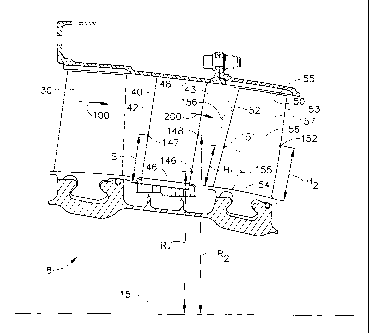
Illustrated in FIG. 2 is a portion of a gas turbine engine fan 5 and booster 7
configured for channeling and pressurizing a bypass airflow 2 and a core
airflow 3
respectively. The booster 7, which pressurizes the air flowing through the
core, is
axisymmetrical about a longitudinal centerline axis 15, and includes an inlet
guide
vane (IGV) stage 11 having a plurality of inlet guide vanes 12 spaced in a
circumferential direction around the longitudinal centerline axis 15, a
plurality of
stator vane stages 17. The booster 7 further includes multiple rotor stages 18
which
have corresponding rotor blades 50 extending radially outwardly from a rotor
hub 19
or corresponding rotors in the form of separate disks, or integral blisks, or
annular
drums in any conventional manner.
Cooperating with each rotor stage, such as for example, the rotor stage 18, is
a corresponding stator stage 17. Each stator stage 17 in the booster 7
comprises a
plurality of circumferentially spaced apart stator vanes 40. The arrangement
of stator
vanes and rotor blades is shown in FIG. 4. The rotor blades 50 and stator
vanes 40
define airfoils having corresponding aerodynamic profiles or contours for
pressurizing
the core air flow 3 successively in axial stages. In operation, pressure of
the air is
increased as the air decelerates and diffuses through the stator and rotor
airfoils.
FIG. 5 shows an exemplary radial sectional of the stator vane airfoil in a two
dimensional axial plane view. As shown in FIG. 5, each stator vane 40 defines
an
airfoil including a generally concave pressure side 44 and a circumferentially
opposite,
generally convex suction side 45. The two sides 44,45 extend chordally between
an
upstream leading edge 42 and an axially opposite, downstream trailing edge 43.
The
booster is a high "throughflow-velocity/wheel speed" design, wherein it is
driven by
low pressure turbines with relatively lower speeds, while the axial air flow
velocity
through the booster is relatively high. Additionally, the hub flow pathway
though the
booster turns radially inward towards the engine centerline. This causes the
radial
-5-
CA 02611336 2007-11-15
208379-3
incidence angle to the airfoils to undergo large variations, especially in the
hub region,
as the booster operates in various flight regimes with varying demands on
airflow.
This is undesirable because stall in a booster may typically originate near
the hub
region of the airfoils. In conventional designs, in order to achieve
operability goals in
the presence of the high radial incidence angle swing imbalance, efficiency is
typically
sacrificed. It is desirable to have a booster design where the requirements
for the stall
margin, including auxiliary electric power extraction, can be achieved without
sacrificing the efficiency.
One way of accomplishing this is by utilizing stator vanes 40 and rotor blades
50 designed to reduce incidence angle swings in the hub regions of the booster
system
during operation. Incidence angle for a rotor blade is defined as the
difference between
the relative inlet air angle 306 measured from the meridional direction (01,
see FIG.
10) and the inlet metal angle 305 determined by the camber line angle at the
leading
edge measured from the meridional direction (131*, see FIG. 10). "Delta
incidence"(AINCIDENCE) is the difference between the incidence angle at stall
line
101 and the incidence angle on the operating line 102. For stator vanes the
same
definitions for incidence angle and "Delta incidence" apply, except that the
air angle is
measured from the meridional direction in the absolute frame of reference. An
exemplary stator vane 40 reduces the incidence flow swing in the booster hub
region
by using a trailing edge 43 having a particular exit swirl angle profile. An
exemplary
exit swirl angle distribution 144 for the exemplary stator vane 40 is shown in
FIG. 6.
FIG. 6 is a plot of the exit swirl angle versus the percent-span. The
incidence angle
swing in hub region of the rotor blades and stator vanes of the booster is
reduced by
adopting a trailing edge 43 with a particular distribution for the exit swirl
angle 140
from the root 46 to the tip 48, where the exit swirl angle is defined as the
air angle
leaving the stator trailing edge measured from the meridional direction
omitting any
secondary flow effects (shown in a 2D axial plane view in FIG. 5).
Conventional
design stator vanes typically result in an approximately linear and
monotonically
increasing swirl angle distribution, such as the distribution 142 in FIG. 6.
In the
exemplary design of the stator vane 40 shown in FIG. 4, the vane has a
tailored exit
swirl angle distribution profile such as, for example item 144 shown in FIG.
6, from
-6-
CA 02611336 2012-09-13
208379-3
the root 46 to the tip 48 of the stator vane 40 such that the exit swirl angle
140 has a
maximum value at an intermediate radius location 148 between a first radius
location
146 and the tip 48.
In a preferred embodiment of the exemplary stator vane 40, the maximum
value for the exit swirl angle (about 22 degrees) in the trailing edge 43
occurs at a
span location of about 70% span height from the root, with the lowest value of
the exit
swirl angle (about 7 degrees) occurring at the root 46 of the trailing edge 43
and the
tip 48 has an exit swirl angle (about 18 degrees) in between the root value
and the
peak value. The incidence swing near the hub region of the booster is
significantly
reduced as compared to a conventional vane resulting in increased stall margin
and
improved efficiency for the booster.
Stall margins for different rotor/stator stages can be improved by suitably
designing the stator vane airfoils with trailing edge exit swirl angle
distributions
similar to the one shown in FIG. 6 item 144. The location of the peak value of
trailing
edge exit swirl angle 140 could be chosen to be at 50% span or higher,
preferably in
the 60% to 80% span range, with the lowest value occurring near the root 46 of
the
stator vane 40. The trailing edge exit swirl angle distributions for the
various stator
stages of a preferred embodiment of a booster system are shown in FIG. 7 on a
non-
dimensional basis, where the exit swirl angle at the tip 48 has been reduced
to a level
that is in the range of 65% to 85% of the exit swirl angle difference between
the
maximum value along the span and the minimum value at the root 46.
In another embodiment of the new stator vane 40 described above, the
leading edge 42 of the stator vane 40 is designed with a sweep angle profile.
Aerodynamic sweep is a conventional parameter represented by a local sweep
angle
which is a function of the direction of the incoming air and the orientation
of the
airfoil surface in both the axial, and circumferential or tangential
directions.
The sweep angle is defined in detail in the U.S. Pat. No. 5,167,489. In the
sign
convention used herein, the aerodynamic sweep angle is represented as a
negative value (-) for forward sweep, and a positive value (+) for aft sweep.
In another embodiment of the stator vane 40 with tailored exit swirl angle
- 7 -
CA 02611336 2007-11-15
208379-3
distribution as described previously, the stator vane leading edge 42 is
designed with a
forward sweep near the root 46 of the airfoil in the hub region of the
booster. This
combination of a stator vane leading edge 42 with a forward sweep near the
root of the
airfoil in the hub region of the booster and a trailing edge 43 with specific
trailing
edge exit swirl angle distribution further improves the aerodynamic
performance and
operability of the booster.
FIG. 8 shows exemplary stator vane leading edge sweep angle distributions
along the span for the various stator stages of an exemplary multistage
booster. In the
preferred embodiment for a multi stage booster, the sweep angle is negative
between
the root 46 and a first span location 147 in FIG. 4 and is positive from the
first span
location 147 to the tip 48. The span height from the root 46 at which the
sweep angle
changes from negative to positive (denoted by "H" in FIG. 8) in a stator vane
40 is a
function of the axial location of the particular stator vane stage. As the air
travels
axially within the booster from the entrance to the exit, it has to undergo
sharp turns
towards the longitudinal centerline axis 15 of the booster prior to entry into
a
compressor located downstream. In the exemplary embodiment of a booster system
7,
the stator vane leading edge sweep angle distributions, as shown in FIG. 8,
are such
that the span height from the root 46 at which the sweep angle changes from
negative
to positive is higher for stator stages located further aft in the booster
system. It is
possible that one or more of the stator stages at the aft end of the booster
may have
stator vanes with leading edges that have a forward sweep only along the
entire span.
In FIG. 8, for example, the stator stage denoted by "S5" is such a stage.
In the preferred embodiment of the booster system 7, the span location from
the root 46 at which the leading edge sweep angle changes from negative to
positive is
about 25% for a forward stage (denoted by "S2" in FIG. 8), 50% for an
intermediate
stage (denoted by "S3" in FIG. 8) and 70 % for a rear stage (denoted by "S3"
in FIG.
8) while the aft-most stage (denoted by "S5" in FIG. 8) has no leading edge
aft sweep.
In the preferred embodiment of the booster system 7, all the stator stages
have stator
vanes 40 such that the leading edge forward sweep at the root 46 for a stator
vane 40
is larger for stator stages located further aft in the booster system and the
stator vanes
40 have tips 48 having less leading edge forward sweep, or more aft sweep,
than at the
-8-
CA 02611336 2007-11-15
208379-3
root 46. In the preferred embodiment of the booster system 7, the stator vane
leading
edge sweep angle at the root 46 is about -3 degrees for the forward-most
stage, about ¨
degrees for the next stage aft, about ¨15 degrees for the rear stage and about
-20
degrees for the rear-most stage. The stator vane 40 leading edge 42 sweep
angle at the
tip 48 is about 13 degrees for the forward-most stage, about 7 degrees for the
next
stage aft, about 5 degrees for the rear stage and about -2 degrees for the
rear-most
stage.
As illustrated in FIG. 2, the booster system 7 in a gas turbine engine
comprises multiple rotor stages 18, with each rotor stage having multiple
rotor blades.
These rotor blades for the various rotor stages are shown in FIG. 3, for
example, as
item 10 for a stage 2 rotor, item 30 for a stage 3 rotor, item 50 for a stage
4 rotor, and
item 70, for a stage 5 rotor. As shown in FIG. 3, the first booster rotor
stage (marked
as "R2") is located immediately aft of the inlet guide vane stage (marked as
"IGV").
Each of the other rotor stages, R3 ¨ R5, is associated with the stator stages
axially
forward and aft from it, with each stator stage having multiple stator vanes.
These
stator vanes for the various stator stages are shown in FIG. 3, for example,
as item 20
for stator stage 2, item 40 for stator stage 3, item 60 for stator stage 4 and
item 80 for
stator stage 5. Air exiting from a stator stage enters the downstream adjacent
rotor
stage and is further compressed by the rotor blades in the rotor stage. As
described in
detail before, the stator vanes in a stator stage are designed to have
specific trailing
edge and leading edge characteristics to improve the operability and
efficiency of the
booster. The operability and efficiency are also influenced by the mechanical
and
aerodynamic design of the rotor blades in the booster. Stall margins and
efficiency of
a compression stage and the booster system can be enhanced by adopting the
specific
design characteristics for the rotor blades as disclosed and described herein.
The reduced incidence swing in the hubs of the airfoils results in a steeper
speedline shape. Such steeper speedlines are shown in FIG. 1 (items 106, 107
and
108).
Blade sweep has been used in fan and compressor blade designs for various
reasons such as noise reduction and performance improvement. In one embodiment
of
-9-
CA 02611336 2007-11-15
208379-3
the present invention of a new rotor blade 50, the blade leading edge 52 has a
new
sweep profile such that in the rate of change of leading edge sweep angle with
respect
to the span height has a substantially constant value along most of the
leading edge
span. In another embodiment, the leading edge sweep angle has a first rate of
change
with respect to the span height that is substantially constant near the blade
root 54, in a
blade inner span region 155, and has a second rate of change with respect to
span
height that is substantially constant along the span up to the blade tip 55 in
a blade
outer span region 156. In the preferred embodiment of the blade, the blade
inner span
region 155 covers a span of about 10% span height measured from the blade root
54.
In another embodiment of the invention, the rate of change of the leading edge
sweep
angle with respect to the span height is substantially constant along the
entire blade
leading edge 52.
FIG. 9 shows an exemplary variation of the leading edge sweep angle along
the span height that is contemplated by the present invention. As shown in
FIG. 9, the
blade leading edge 52 has a forward sweep (negative sweep angle) near the root
of the
blade and an aft sweep (positive sweep angle) away from the root region. The
rate of
change of the leading edge sweep angle with respect to span height and the
location of
the blade first height 151 on the blade leading edge 52 where the transition
from
forward sweep to aft sweep occurs are chosen such that the flow coming out of
the
stator vanes, such as for example, stator vane 40 in FIG. 4, enters the rotor
blades,
such as for example, blade 50 in FIG. 4, with increased efficiency and is
directed
towards the hub region of the rotor in a manner to increase the operability
and
efficiency of the rotor. As discussed previously, stall in a booster typically
originates
near the hub region over the higher power ranges where the booster bleed valve
operates closed. Having the unique characteristics of the blade leading edge
52
described herein increases the stall margin for the booster. In the preferred
embodiment of the booster, all the rotor stages have rotor blades that have
substantially the same characteristic linear variation of the leading edge
sweep angle
with span height, as shown in FIG. 9.
FIG. 10 shows a radial sectional view through the airfoil of an exemplary
rotor blade. In another aspect of the invention, the locations of the maximum
thickness
-10-
CA 02611336 2007-11-15
208379-3
302 (identified as "Tmax", see FIG. 10) of the rotor blade airfoil sections
300 are
chosen such that they are located closer to the leading edge 52 at higher span
locations
from the blade root 54 and the relative distance of the Tmax location from the
leading edge varies in a substantially linear manner with respect to the span
height
from the blade root 54 to the blade tip 55. In this context, the "relative
distance" is
defined as the ratio of the axial distance "d" 303 (see FIG. 10) of the Tmax
location
along an axial line from the blade leading edge 52 to the axial chord length
"C" 301
(see FIG. 10) of the airfoil section 300 at a particular span height.
Locating Tmax 302 near the blade leading edge 52 at higher span heights
from the blade root 54 results in higher wedge angles for the blade leading
edge 52 in
the radially outer sections of the blade airfoil. The higher wedge angles
result in
leading edge shapes in the outer airfoil sections which improve incidence
angle range
and operability of the booster, in addition to being mechanically robust. It
may be
noted that the characteristic of locating Tmax progressively proximate to
blade leading
edge in outer span regions, and designing multiple booster rotor stages such
that Tmax
is located relatively closer to the leading edge in the front stages than the
rear stages,
as shown for example in FIG. 11, are contrary to the conventional practice in
the
design of compression system airfoils. In conventional designs the Tmax
locations of
various airfoil sections are chosen based on mechanical design considerations
such as
blade frequencies.
A preferred embodiment of this characteristic of Tmax locations is shown in
FIG. 11 for the various rotor stages of the booster system. In the preferred
embodiment of the rotor blade, the relative distance is about 0.4 at the root
and is
about 0.2 at the tip. The variation of the relative distance with respect to
the span
height is substantially linear, as shown in FIG. 11. In the preferred
embodiment of the
booster system, the characteristic variation of the relative distance with
span height is
substantially the same for the rotor blade airfoils in multiple rotor stages,
as shown in
FIG. 11 for R2, R3, R4 and R5 rotor stages.
One of the ways the operability of the booster system is improved is by
directing more flow towards the hub region, as the air traverses the axial
path with
large curvatures through the booster. One of the parameters of blade design
which can
-11-
CA 02611336 2012-09-13
208379-3
be used influence the flow directions is the dihedral angle at a particular
location.
Dihedral exists, for example, when the blade surface is not normal to the hub.
As used
herein, the definition of "Dihedral" or, alternatively, "Dihedral Angle", is
the same as
that outlined in the paper "Sweep and Dihedral Effects in Axial-Flow
Turbomachinery", Leroy H. Smith, Jr., and Hsuan Yeh, Journal of Basic
Engineering,
Transactions of ASME, 62-WA-102, 1962.
In another aspect of the invention of a new rotor blade, the performance and
operability of the booster system is improved by adopting a new dihedral angle
profile
at the trailing edge 53 that particularly matches the new blade leading edge
52 sweep
rate of change with the span height and the variation of the location 303 of
the
maximum airfoil thickness 302 described before. FIG. 12 shows an exemplary
distribution of the dihedral angle at the trailing edge 53 of the rotor blade
with respect
to the span height. A negative dihedral angle at a point on the blade means
that the
normal to the pressure surface of the blade at that location points towards
the
longitudinal centerline axis 15 of the booster system. As shown in FIG. 12,
the trailing
edge dihedral angle is lowest at the blade root 54, adjacent to the booster
hub and is
negative between the blade root 54 and a second height location "H2" 152 (see
FIG.
4) on the trailing edge 53. The dihedral angle becomes less negative as the
span height
increases, becoming positive at an intermediate span height location,
thereafter
reaching a maximum value, and decreasing thereafter towards the tip.
In the preferred embodiment of the rotor blade, the dihedral angle is about ¨
15 degrees to ¨20 degrees at the blade root 54, and remains negative up to a
span
height of about 20% from the blade root 54., In the preferred embodiment of a
booster
system with multiple rotor stages, the trailing edges 53 of the blades in
multiple rotor
stages have negative dihedral angles near the hub region, from the blade root
to about
20% to 30% span height.
While there have been described herein what are considered to be preferred
and exemplary embodiments of the present invention, other modifications that
fall
within the scope of the invention shall be apparent to those skilled in the
art from the
teachings herein.
- 12-