Note : Les descriptions sont présentées dans la langue officielle dans laquelle elles ont été soumises.
CA 02612348 2007-11-27
1 "RECYCLING OF OIL-BASED DRILLING MUDS"
2
3 FIELD OF THE INVENTION
4 Embodiments of the invention relate to processes for recycling
hydrocarbon and synthetic base oils from drilling fluids and more particularly
to
6 processes of removing ultra-fine particulate materials for recycling the
base oil
7 for use in preparing drilling fluids without the need to add additional
emulsifiers.
8
9 BACKGROUND OF THE INVENTION
Water-in-oil emulsions (oil-mud) are often used in circulating fluids
11 required in the rotary drilling of formations containing hydrocarbons. The
12 circulating fluids are referred to as drilling muds. The common
specification of
13 the term "mud" is defined according to its usual meaning in the oil and gas
14 drilling industries, namely to describe a drilling fluid used to transport
rock
cuttings from a wellbore.
16 Such fluids or mud formulations are typically tailored to specific
17 well bore conditions and are costly to formulate. The most expensive
component
18 of oil-mud systems is the hydrocarbon or synthetic base oil used as the
fluid
19 matrix for such systems. One objective in the process of drilling is,
therefore, to
conserve drilling muds, and where possible recycle and reuse the base oil.
21 Oil-mud circulating fluids are pumped down the drill pipe and out
22 into the wellbore through holes in the drill bit and are recirculated back
up the
23 well in the annular space between the drill pipe and walls of the well
bore,
24 carrying with it drill cuttings and the like that are then removed before
recirculation. The mud performs a number of functions, including removing
drill
CA 02612348 2007-11-27
1 cuttings, lubricating and keeping the bit cool, providing flotation to help
support
2 the weight of the drill pipe and casing, providing hydrostatic pressure to
prevent
3 caving in and undesirable flow of fluids and/or gases in or out of the well
bore,
4 including drilling fluids, brine, and the like.
The properties and composition of the drilling mud formulations are
6 complex and variable, depending on the conditions involved and the results
7 desired or required including the ability to reuse and recycle the mud
8 formulations. In oil mud-drilling fluids, the oil, hydrocarbon or synthetic,
is the
9 continuous phase and the water is present in a dispersed phase. This is
necessary to maintain the required rheology of the mud for drilling and
11 completion, including a balance between gel strength and viscosity, i.e.,
the
12 balance for example between pumpability of the mud and its hole cleaning
13 capability. Further, it is necessary to maintain the oil phase as the
external phase
14 in order to keep the drilled solids oil-wet to prevent the solids from
coming in
contact with water and easily dispersing in the mud.
16 Mud solids include particles that are drilled from the formation,
17 material from the inside surface of the hole and materials that are added
to
18 control the chemical and physical properties of the mud, such as weight
material,
19 including but not limited to barite and calcium carbonate and the like.
Drilled
solids' particles are created by the crushing and chipping action of rotary
drill
21 bits. Additional solids enter the well bore by sloughing from the sides of
the open
22 hole. From the time they enter the well until they reach the surface,
drilled solids
23 particles are continuously reduced in size by abrasion with other particles
and by
24 the grinding action of the drill pipe.
2
CA 02612348 2007-11-27
1 If mud solids are not properly controlled, the mud's density can
2 increase above its desired weight and the mud can get so viscous that it
creates
3 difficulties in pumping the fluid. The increase in density can become
critical if the
4 density exceeds the pore pressure of the formation which can lead to loss of
the
fluid and increased costs related thereto. Since the earliest days in the oil
6 industry, drillers have been trying to combat high solids content through
the use
7 of settling pits. However, some drilled solids are so finely ground that
they tend
8 to remain in suspension regardless how long they are allowed to settle. The
fine
9 solids in suspension result in increased mud viscosity and gel strength,
which in
turn results in larger particles also remaining in suspension. Thus, the
approach
11 of removing cuttings through settling alone is of limited practical value.
12 Of primary detriment to drilling fluids are ultra fine (5pm to 30 pm)
13 and colloidal (0.1 Nm to 5pm) size drill cutting particles. These small
particles, if
14 not removed, create havoc in a variety of ways. They slow the rate of
penetration
(ROP) compounding the number of rig days required and the cost. They disrupt
16 the drilling fluid rheology, especially gel strengths, thereby upsetting
the
17 Equivalent Circulating Density (ECD), risking mud losses and worse,
creating
18 potential blow out situations. Ultra fine particles and colloidal particles
cannot
19 typically be removed by shale shakers, de-sanders, de-silters, or mud
cleaners.
Conventional centrifuges can typically only remove solids down to about 10-
21 20Nm. Under conventional methodologies, ultra fine particles and colloidal
22 particles create the need for excessive dilution to control the fluid
density thus
23 escalating mud cost and worse, contributing to environmental disposal
problems
24 by excessive mud build-up.
3
CA 02612348 2007-11-27
1 Based on studies done in the early 1970's, ultra-fine colloidal solids
2 have the most detrimental reduction effect on ROP. Research has demonstrated
3 that doubling colloidal content, though it may be only a relatively small
part of
4 overall solids volume, can reduce ROP by as much as 70-80%. As the solids
surface area grows, water demand and chemical demand of the fluid grows,
6 exponentially increasing demand for hydraulic horsepower, driving up plastic
7 viscosity and creating sticky, spongy cakes on the wellbore walls.
8 Further, ultra-fine solids are not the only contaminants of invert-
9 emulsion drilling muds. Additional aqueous fluids that can be introduced
into
these systems can lead to significant difficulty in the recovery of the base
oil
11 fluid. During the drilling process, it is also not uncommon for the
drilling fluid to
12 encounter a water bearing formation and thus, the ratio of aqueous fluid to
non-
13 aqueous fluid is less than optimal. In some cases, the formation of a
difficult-to-
14 break emulsion occurs and this is often referred to as the "slop". The oil
to water
ratio in the slop may be 25/75 or 30/70 or similar such numbers. Using
16 conventional methods of emulsion breaking it is possible to recover, for
example,
17 a 60/40 ratio of oil to water fluid. The recovered oil is then diluted with
additional
18 make up oil to achieve the desired ratio, being typically 80/20. One of the
19 primary difficulties associated with this system is the use of emulsion
breakers
and surface tension breakers that are not environmentally friendly. There are
21 many citations in the literature that deal with the separation of the
excess
22 aqueous fluids from invert-emulsion drilling fluids, such as United States
Patent
23 6,881,349 to Mueller and United States Patent 6,977,048 to Mueller.
24 Drilling fluids made up of expensive polymers and oil base
synthetics demand high performance decanters to control excessive mud cost.
4
CA 02612348 2007-11-27
1 As the drilling parameters become more and more complex, involving high
2 temperature additives, etc., the need to remove ultra fine and colloidal
particles
3 from the mud becomes paramount.
4 Drilling performance is typically optimized by the use of oil based or
synthetic based mud. However, in an attempt to make these technologies more
6 commonplace and acceptable from an economic standpoint, there is a definite
7 need to be able to use the fluid systems as many times as possible. Further,
8 there is a need to avoid major environmental issues created by the disposal
of
9 waste material generated from the use of these systems.
There are a number of different methodologies noted in the
11 literature for cleaning of drill solids, but very little has been done to
address the
12 recovery and reuse of the hydrocarbon base oil from an economic standpoint,
13 which may lead to reduced oil and gas exploration costs.
14
SUMMARY OF THE INVENTION
16 Embodiments of the invention provide a substantially universal
17 drilling mud recycling method for oil-based drilling mud which utilize
surfactants
18 or emulsifiers which are lime/fatty acid based. Hydrocarbon and synthetic
base
19 oils are recovered according to embodiments of the method of the invention,
the
recovered base oils comprising substantially all of the emulsifiers from the
drilling
21 mud and at least a portion of the organoclays. Later, addition of lime to
the
22 recovered hydrocarbon base oil is sufficient to reactivate the recovered
23 emulsifiers for preparation of a new drilling mud.
24 In a broad aspect a method for recovering a hydrocarbon base oil
from used water-in-oil emulsion drilling mud containing drilled solids
comprises:
5
CA 02612348 2007-11-27
1 adding a surfactant, the amount of the surfactant being sufficient only to
prevent
2 viscosity increases in the drilling mud as a result of at least partial
water-wetting
3 of organoclays in the drilling mud; mixing the dispersant with the used
drilling
4 mud; adding an acid, the acid selected for having low affinity for the base
oil
phase of the drilling mud, to the surfactant-treated used drilling mud,
sufficient to
6 reduce the pH of a water phase of the drilling mud to a value of less than
about 7
7 for deactivating emulsifiers in the used driiling mud; mixing the surfactant-
treated
8 drilling mud with the acid for sufficient time to deactivate the
emulsifiers; and
9 separating the base oil phase from the water phase and from at least the
drilled
solids contained therein, wherein the recovered base oil contains at least
11 substantially all of the deactivated emulsifiers.
12 In another broad aspect of the invention the method further
13 comprises, after the step of separating the base oil from the water phase
and at
14 least the drilled solids: adding lime to the recovered base oil in an
amount
sufficient to reactivate the emulsifiers contained in the recovered base oil
for use
16 in preparing a new drilling mud.
17 In one embodiment, the acid further comprises a non-emulsifier in
18 an amount sufficient to prevent the acid from forming an oil-in-water or an
oil-in-
19 water-in-oil emulsion in the drilling mud.
In one embodiment the acid further comprises a corrosion inhibitor
21 in an effective amount to prevent corrosion of mixing equipment and the
like
22 used in a process for recovering the base oil.
23
6
CA 02612348 2007-11-27
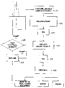
1 BRIEF DESCRIPTION OF THE DRAWINGS
2 Figure 1 is a schematic illustrating a recovery process for
3 recovering at least a base oil from used driliing mud; and
4 Figure 2 is a schematic illustrating a recycling process whereby the
recovered base oil according to Fig. 1 is treated to reactivate emulsifiers
therein
6 for forming a new drilling mud.
7
8 DESCRIPTION OF THE PREFERRED EMBODIMENTS OF THE INVENTION
9 A hydrocarbon or synthetic oil-based drilling fluid typically
comprises a continuous oil phase; a brine phase; emulsifiers and wetting
agents;
11 lime; organoclay and at least one weighting agent. The oil based drilling
fluid
12 typically exists as a water/brine-in-oil emulsion. The emulsiflers used to
create
13 the emulsion are typically fatty acids or derivatives thereof. The emulsion
is
14 created by reacting lime (calcium hydroxide) with a fatty acid(s) to create
a
calcium fatty acid soap. The brine phase is usually calcium chloride, but can
16 consist of other salts and is added to the oil with shear to create the
emulsion. In
17 order to stabilize the emulsion and prevent separation an organoclay
(viscosifier)
18 is added. Organoclays are swelling clays that have been chemically modifled
to
19 swell in oil rather than water. Typically, the organoclays have been
chemically
treated with a quaternary amine. Weighting agents are added to the system to
21 increase the density of the fluid to counteract the formation pressures.
Typical
22 weighting agents are barite and calcium carbonate.
23 Embodiments of the invention comprise overcoming the
24 mechanisms that stabilize the emulsion which includes neutralizing the
emulsifiers, typically fatty acid and iime which form soaps, present in solids-
7
CA 02612348 2007-11-27
1 contaminated drilling fluid which has been retumed from a wellbore. The
fatty
2 acid emulsifiers, when neutralized, become inactive in the oil phase of the
drilling
3 fluid and no longer support the emulsion stability and, by extension, the
stability
4 of the drilling mud. The reduction in viscosity and emulsion stability aids
in
allowing the solids to be removed using conventional methodologies such as
6 centrifugation.
7 In embodiments of the invention, neutralizing the fatty acid and
8 lime is achieved by the addition of an acid selected to have little affinity
for the
9 oil, typically a mineral acid such as sulphuric acid or more preferably
hydrochloric acid. If sulphuric acid is used, the calcium source precipitates
and
11 may create some additional viscosity issues however, if hydrochloric acid
is used
12 the calcium source is solubilized.
13 Sufficient acid is added to the solids-containing drilling mud to
14 reduce the pH of the water-phase to a value less than 7 and preferably to a
value less than 4. Neutralizing the fatty acid to a pH of approximately pH 4
or
16 less deactivates the emulsifiers, but does not destroy or break down the
17 emulsifiers and therefore the emulsifiers may be reactivated again upon the
18 addition of lime once the solids have been removed, such as by
centrifugation.
19 As the same mechanism that lends stability to the water-in-oil
emulsion also aids in the ability of the solids to be oil-wet, use of acids to
21 neutralize the fatty acid and lime results in water wetting of the solids,
which
22 enhances the ability to remove the solids using conventional methodologies
such
23 as centrifugation. The at least partial water-wetting which occurs upon
24 neutralizing the emulsifiers in the drilling mud using embodiments of the
invention however may also create additional problems because the water
8
CA 02612348 2007-11-27
1 present in the fluid is able to fully activate the organoclays. While
organoclays
2 produce 2-D viscosity networks as a result of the clay platelets being
dispersed
3 in the oil phase, a significant increase in viscosity occurs when the clay
platelets
4 are allowed to form a 3-D network via hydrogen bonding of the hydroxyl
groups
on the clay edges with the water droplets emulsified in the oil. The presence
of a
6 large amount of free water as a result of neutralizing the emulsifiers
causes the
7 organoclay to yield and potentially result in up to a five-fold increase in
viscosity
8 which is detrimental to the removal of the solids.
9 In order to combat the effect of water wetting on the organoclay, a
dispersant or surfactant is added. Conventional surfactants which act to
reduce
11 viscosity by preventing water-wetting of organoclays in the muds are
acceptable.
12 Anionic surfactants have been found to be of particular use. It is commonly
13 known to those skilled in the art that dodecylbenzene sulphonic acid
(DDBSA)
14 acts as a dispersant to decrease the viscosity of greases when organoclays
have been used as gellants. Applicant has found however that surprisingly,
16 DDBSA can also be used to overcome 3-D viscosity build-up, a phenomenon not
17 previously noted in the literature. Applicant believes it is likely that
the DDBSA
18 sterically hinders the organoclay from forming any hydrogen bonding with
the
19 water droplets and hence prevents the 3-D network from forming.
Sufficient surfactant, such as DDBSA, is added to prevent
21 unacceptable increases in viscosity due to the water wetting which occurs
as a
22 result of the neutralization of the fatty acid and lime.
23 Drilling fluid emulsions are typically very complex systems that
24 contain a variety of surfactants. The inactivation of drilling mud
emulsifiers with
respect to the emulsifiers' ability to stabilize water-in-oil emulsions may
lead to
9
CA 02612348 2007-11-27
1 the conversion of the drilling mud system from an oil-external emulsion to a
2 water-external emulsion or an oil-in-water-in-oil emulsion which is
detrimental to
3 the separation of solids therefrom.
4 Applicant has found that use of a non-emulsifier, when added in
amounts sufficient only to prevent the acid forming an oil-in-water and/or an
oil-
6 in-water-in-oil emulsion in the solids-containing drilling mud,
significantly aids in
7 the efficiency of separation of the ultra-fine solids from the base fluid.
The non-
8 emulsifiers do not act to counteract the emulsifiers in the solids-
containing
9 drilling mud as the non-emulsifier is selected to substantially partition to
the
aqueous phase rather than the oil phase. Suitable non-emulsifiers may be, but
11 are not limited to, polyalkylene glycols, resin oxyalkylates, amine
oxyalkylates,
12 mixed sulphonates, resin esters and diepoxides. One such suitable non-
13 emulsifier is NE005 available from Innovative Chemical Technologies Canada
14 Ltd. of Calgary, Alberta, Canada.
In embodiments of the invention, a corrosion inhibitor is added in
16 amounts sufficient to prevent the acid, which is added to neutralize or
inactivate
17 the emulsifiers, from corroding metal surfaces such as on the rig or in
mixing
18 equipment. Typically corrosion inhibitors suitable for use in embodiments
of the
19 invention must be soluble and stable in the acid. Such corrosion inhibitors
typically contain acetylenic alcohols, quinoline quatemary amines, alkyl
benzyl
21 quaternary amines, potassium or copper iodides or mixtures thereof.
Applicant
22 has found one such suitable corrosion inhibitor to be CA 5051, available
from
23 Innovative Chemical Technologies Canada Ltd. of Calgary, Alberta, Canada,
24 In addition to embodiments of the invention having the ability to
efficiently destabilize spent colloidal drilling mud systems to yield low
density
CA 02612348 2007-11-27
1 base-oil that can be reused to make "new" muds, embodiments of the invention
2 also result in water-wetting of the finely dispersed ultra-fine and
colloidal solids
3 which allow the finely dispersed ultra-fine and colloidal solids to be
separated
4 from the base-oil and water phases. Typically separation is effected through
centrifugation and the like.
6 Embodiments of the invention have been able to yield recycled
7 base-oil with a purity of between about 90% to about 100% and with a total
8 base-oil recovery of between about 50% to about 100%.
9
METHOD OF TREATING A SOLIDS-CONTAINING DRILLING MUD
11 As shown in Fig. 1 and in an embodiment, the invention comprises
12 a method in which the concentration of drilled solids in used drilling
muds, which
13 have been returned from the welibore, can be reduced below that possible
using
14 mechanical separation alone.
Used drilling mud at 101 is first pre-treated by mixing with from 0%
16 to about 10% by volume of a suitable surfactant at 102, for example Dodecyl
17 Benzene Sulphonic Acid (DDBSA). More preferably, the used drilling mud is
18 mixed at 103 with from about 0% to about 3% by volume DDBSA to inhibit the
19 development of additional viscosity caused by the addition of aqueous fluid
to
the emulsified mud system.
21 The surfactant-treated drilling mud is then treated by the addition of
22 an acid at 104 and mixed at 105 therewith for neutralizing the emulsifiers
23 contained therein. The neutralization of the fatty acid is accomplished
through
24 the addition of from about 1% to about 10% by volume of 1% to about 36% by
weight hydrochloric acid (HCI) and more preferably through the addition of
from
11
CA 02612348 2007-11-27
1 about 10% to about 60% of 5% to about 28% by weight HCI containing from
2 about 0% to about 10% by weight of a suitable non-emulsifier. More
preferably,
3 the non-emulsifier is added from about 0% to about 3% by weight. Sufficient
4 non-emulsifier is added to prevent the acid from being emulsified in the
drilling
mud before the acid can fully neutralize the fatty acids and thereby
deactivate
6 the emulsifiers present therein. Once the emulsifiers are deactivated, such
as
7 evidenced by measurements of fluid rheology including but not limited to
8 electrical stability and yield point, the drilling mud can be separated at
106 to
9 recover the base oil which contains substantially all of the deactivated
emulsifiers. Typically the separation is achieved by centrifugation.
11 In one example representative of embodiments of the invention, a
12 sample of about 250mL of a solids-contaminated drilling mud was treated
with
13 1% by volume DDBSA (2.5mL) and was mixed for 15 minutes. Following mixing,
14 100 mL of an acid formulation (40% by volume) containing 9% by weight HCI,
1% by weight non-emulsifier (NE005) and 0.2% by weight corrosion inhibitor (CA
16 5051) was added and the resulting fluid mixed for between 2 to 16 hours to
17 achieve neutralization of the emulsifiers contained within the used
drilling mud.
18 Following mixing with the acid formulation, the sample was centrifuged to
19 separate the base oil, containing substantially all of the deactivated
emulsifiers,
from the aqueous phase and the solids.
21 Should the used drilling mud contain drilled solids in excess of 10%
22 by volume, the additional viscosity makes separation of the solids using
23 embodiments of the invention more difficult, Applicant has found however
that
24 these difficulties can be overcome.
12
CA 02612348 2007-11-27
1 One method of overcoming the problems associated with
2 excessive viscosity is to dilute the spent mud with additional virgin base-
oil to
3 reduce the solids per volume. The added virgin base-oil is recovered with
the
4 recovered base-oil.
Optionally, in the case of highly viscous spent mud, additional
6 surfactant, such as DDBSA, may be added to the spent drilling mud to assist
7 with reducing the initial elevated viscosity.
8 Altemately, high gravity solids may be removed by known
9 methods, such as centrifugation, prior to treating the spent mud using
embodiments of the invention.
11
12 REFORMULATION OF A DRILLING MUD USING RECOVERED BASE OIL
13 Applicant has found that because embodiments of the invention
14 neutralize, but do not destroy, the emulsifying properties of the fatty
acid
surfactants used in the drilling fluid, it is possible to easily and cost-
efficiently
16 regenerate a new drilling fluid using the recycled base-oil.
17 Embodiments of the invention not only neutralize the mechanisms
18 that provide stability to the water-in-oil emulsions system, but also
ensure that
19 those components responsible are kept substantially mostly in the oil phase
rather than being substantially lost to either the aqueous phase or on the
surface
21 of the solids present.
22 One skilled in the art would understand that should a process
23 utilize complete destruction of the surfactant or emulsifier components to
attempt
24 efficient separation of the ultra-fine and colloidal solids, such a process
would be
less economical than embodiments of the invention. Upon recycle of the base-
13
CA 02612348 2007-11-27
1 oil, using such a destructive process, there would be a need to add
emulsifier
2 and organophilic clay components to replace those which were destroyed
before
3 a new drilling mud of similar properties can be made.
4 Having reference to Fig. 2, and because embodiments of the
invention do not destroy the surfactants (emulsifiers) during application of
6 embodiments of the invention at steps 101 to 106, but were instead kept
7 substantially soluble in the oil phase, a "new" drilling fluid can be remade
without
8 having to add substantial amounts of either primary and secondary emulsifier
9 components or organophillic clay components.
Lime is added at 107 in amounts sufficient to elevate the pH of the
11 base oil containing the deactivated emulsifiers. The pH is sufficiently
elevated to
12 reactivate the emulsifiers such as evidenced by measurements of emulsion
13 stability, such as electrical stability and yield point at 108. Thus a
drilling fluid
14 can be recreated from recycled base oil without the addition of significant
amounts of at least the emulsifier.
16
17 EXAMPLES
18 Testing was conducted as per the American Petroleum Institute
19 Bulletin RP 13B-2, 1998. The following abbreviations may be useful in
interpreting the results described in the following examples:
21 PV Plastic Viscosity (m.Pa.s) - a parameter of a rheological model
22 used to characterize the viscosity of a drilling fluid.
23 YP Yield Point (Pa) - a parameter of a rheological model used to
24 characterize the viscosity of a drilling fluid.
14
CA 02612348 2007-11-27
1 ES Electrical Stability - indicates the strength of the emulsion, the
2 higher the value the stronger the emulsion.
3 po;l - density of oil recovered after centrifugation as measured by the
4 Mettler Toledo Densitometer 30P.
6 EXAMPLE 1
7 The effectiveness of neutralization of the emulsifiers was tested
8 using an embodiment of the invention to water wet the solids and remove the
9 solids from the oil phase. Following treatment with an embodiment of the
invention, a portion of the treated sample was centrifuged to remove the
solids
11 and a variety of individual tests were performed. As shown in Table 1, 11
12 samples are shown. Samples 10 and 11 are included to show that increasing
13 acid volume did not further affect the density of the recovered oil.
14 Each 250mL sample of solids-containing drilling fluid was added to
a beaker and placed on to a paddle mixer at 200 rpm.
16 The properties of the drilling fluid samples prior to testing were as
17 follows:
18 1. Density: 1000 kg/m3
19 2. Oil/Water Ratio (OWR): 90/10
3. Drilled Solids Concentration: 6% "/õ
21 4. Plastic Viscosity: 18 m.Pa.s
22 5. Yield Point: 2.5 Pa
23 6. Electrical Stability: 910
24
CA 02612348 2007-11-27
1 Sample 1 was not subjected to treatment according to
2 embodiments of the invention and was separated by conventional
centrifugation
3 alone.
4 Dodecylbenzene sulphonic acid (DDBSA) 10 I/m3 (50% activity)
was added to each of samples 2-11 and mixed for 15 minutes. An acid
6 formulation according to an embodiment of the invention and having an acid
7 (HCI) concentration as identified in Table 1 and containing the non-
emulsifier
8 (NE005) was added and the resultant mixture was mixed on the paddle mixer
for
9 16 hours. The %v/v of acid added was varied in samples 2-5, 6-9 and 10-11.
The
% v/v DDBSA was added at 2% v/v for samples 2-5 and at 1% v/v for samples 6-
11 11.
12 After mixing, 100mi of each treated sample was centrifuged at
13 1200 rpm for 10 minutes on a Damon/IEC HN-S centrifuge, available from
14 ThermoFisher Scientific of Waltham, MA, USA. The density of the recovered
oil
was measured. The viscosity of the fluid was measured at room temperature
16 using an OFITE Model 900 viscometer, available from OFI Testing Equipment
17 Inc. of Houston, Texas, USA.
16
CA 02612348 2007-11-27
1 Table 1
# Mix %V/v % %V/v %V/v PV YP ES pH poii
Time HCI Conc" NE005 DDBSA
HCI
1 0 - - - 15 1.5 910 - 0.950
2 16 30 20 1 2 29 1.5 100 7 0.895
3 16 40 20 1 2 30 3 60 5 0.878
4 16 50 20 1 2 22 2 40 4 0.870
16 60 20 1 2 21 3.5 40 3 0.867
6 16 30 20 1 1 29 0.5 105 7 0.887
7 16 40 20 1 1 28 2.5 85 5 0.871
8 16 50 20 1 1 28 3.5 50 4 0.858
9 16 60 20 1 1 24 3 35 3 0.856
16 30 40 1 1 28 3.5 75 1 0.860
11 16 40 40 1 1 29 3 60 1 0.859
2
3 One skilled in the art can see that embodiments of the invention
4 are capable of reducing the solids load in the drilling fluid as evidenced
by the
5 reduced poii over that of conventional centrifugation alone as seen in
sample #1.
6 Ideally the density of the recovered base oil should approach that
7 of the virgin base-oil which was, in this case, about 0.84.
8 Applicant believes that density values in excess of 0.84 are due to
9 the presence of the inactivated emulsifiers and amounts of organoclays which
10 are retained in the base oil and which are advantageous in use to create
new
11 drilling muds.
17
CA 02612348 2007-11-27
1 EXAMPLE 2
2 Samples of solids contaminated drilling fluid were treated
3 according to embodiments of the invention using different v/v% DDBSA to
4 illustrate that DDBSA, a known demulsifier and dispersant, acts as an
exceptional surfactant to reduce the viscosity, especially the PV, as
described
6 herein and which aids in removing the solids. The same treatment method was
7 used as in Example 1 and the results are shown below in Table 2.
8
9 Table 2
# Mix %V/V % %"/V %"/v PV YP ES Poil
Time HCI Conc" NE005 DDBSA
HCI
1 0 - - - - 15 1.5 900 0.950
2 16 40 20 0 0 48 5.5 170 0.925
3 16 40 20 1 0 47 4.5 150 0.920
4 40 20 20 1 1 17 3 40 0.855
5 16 40 20 1 2 19 2.5 55 0.859
11 One skilled in the art can see in samples 4 and 5, that DDBSA aids
12 in dispersing the organoclay and drilled solids as shown by the lower
plastic
13 viscosity (PV) and also aids in reducing the emulsion strength as shown by
the
14 lower electrical stability (ES).
The resulting recovered base oil has a lower density, approaching
16 an ideal density, being that of the virgin base oil used in a drilling
fluid.
17
18
CA 02612348 2007-11-27
1 EXAMPLE 3
2 Testing was conducted to illustrate the effect of different mixing
3 times. The same test procedure was used as in Example 1 however the drilling
4 fluid samples were obtained from a different wellbore. The drilling fluid
had the
following properties:
6 1. Density:1100 kg/m3
7 2. Oil/Water Ratio (OWR): 91/9
8 3. Drilled Solids Concentration: 7% v/v
9 4. Plastic Viscosity: 22 m.Pa.s
5. Yield Point: 4.5 Pa
11 6. Electrical Stability: 1260
12
13 Table 3
# Mix %V/v % Conc" %"/v %V/v PV YP ES Poii
Time HCI HCI NE005 DDBSA
1 2 40 25 1 1 47 13 105 0.865
2 4 40 20 0 0 42 11 105 0.867
3 6 40 20 1 0 38 9 100 0.865
4 16 20 20 1 1 33 7 100 0.865
5 - - - - - 22 4.5 1260 0.920
14
It was noted that the electrical stability was higher than in the
16 drilling fluid used in Example 1 which is an indication that there was more
17 emulsifier present in the drilling fluid used in this example. A higher
18 concentration of acid was therefore required for neutralization of the
increased
19 amount of emulsifier.
One skilled in the art can see that mixing time had a negligible
21 affect on the density of the recovered oil.
19
CA 02612348 2007-11-27
1 EXAMPLE 4
2 Testing was conducted to confirm that the recovered oil could be
3 re-used to make another drilling fluid. The recovered oil was recovered as
per
4 Example 1 and was used for the preparation of two drilling fluid
formulations
(Formulation 1 and 2). The recovered oil had a density of 0.853 kg/m3. The
6 formulations used were:
7
8 Table 4
Additive Name Formulation I Formulation 2
Recycled Base Oil 221.7 198.5 g
EM 1000 3.5 ml 4 ml
EM 1200 0.35 ml 0.7 ml
Bara e13000 Or anocla 4 3
Lime 5 5
Calcium Chloride (94%) 10.5 9.4
Water 29.3 ml 26.4 ml
Barite 176.6 310.5
OWR 90/10 90/10
Density 1300 k/m 1600 k/m
9
EM 1000 is a primary/secondary emulsifier package supplied by ICTC
11 EM 1200 is a wetting agent supplied by ICTC.
12
13 The following procedure was utilized to prepare the drilling fluid
formulations.
14 Mixing was performed using a Hamilton Beach Mixer on low setting:
= Add emulsifiers to base oil and mix for 2 minutes.
16 = Slowly add lime and mix for 8 minutes.
17 = Slowly add Barage13000 and mix for 10 minutes
18 = Slowly add brine (Calcium Chloride and Water) and mix for 20 minutes
19 = Slowly add Barite and mix for the remaining time to a total mixing time
of
60 minutes.
21
CA 02612348 2007-11-27
1 Once the formulations were prepared, each formulation was hot
2 rolled at 250 F for 16 hours in ageing cells pressurized to 100psi with
nitrogen to
3 simulate use in a wellbore. Subsequent rheology and ES testing was performed
4 at 50 C.
6 Table 5: Before hot rolling
Formulation 600 300 200 100 6 3 rpm PV YP ES
rpm r m r m rpm rpm
1 45 26 19 11 2 1.5 19 3.5 1000
2 56 31 23 15 4 3.5 25 3 960
7
8 Table 6: After hot rolling
Formulation 600 300 200 100 6 3 PV YP ES
rpm r m r m rpm rpm rpm
1 49 28 20 14 5 5 21 3.5 670
2 57 34 26 18 7 7 23 5.5 720
9
While acceptable parameters vary from operator to operator, it is
11 generally thought that an ES of > 500 is an acceptable result following hot
12 rolling. Values are obtained at different rpm's (600 - 3) as representative
of
13 subjecting the mud to different shear rates.
14 Following hot rolling of the drilling fluid formulations, the
formulations were recycled again using embodiments of the invention as
16 described in Example 1. The density of the recovered oil was 0.880 kg/m3.
17 It should be noted that the experimentation done in Example 4 was
18 performed before Applicant had confirmed that additional emulsifiers were
not
19 required and therefore emulsifiers EM1000 and EM1200 were added but were
not required.
21
CA 02612348 2007-11-27
1 One skilled in the art can see that drilling fluids can be made using
2 base oil recovered according to embodiments of the invention.
3
4 EXAMPLE 5
Testing was conducted to confirm that the recovered oil could be
6 re-used to make another drilling fluid without the use of any additional
emulsifier.
7 The oil was recovered as per Example 1 and was used to create the following
8 formulation (Formulation 3). Testing procedures were used as in Example 4.
9
Table 7:
Additive Name Formulation 3
Recycled Base Oil 252.3 g
Baragel 3000 Or anocla 6
Lime 5 g
Calcium Chloride (94%) 11.9
Water 33.2 ml
OWR 90/10
Density Unwei hted
11
12 Tables 8 and 9 show the results of the fluid testing before and after
13 hot rolling.
22
CA 02612348 2007-11-27
1 Table 8: Before hot rolling
Formulation 600 300 200 100 6 3 PV YP ES
rpm
rpm rpm rpm rmrm
3 34 20 16 10 2.5 2 14 113 1260
2
3 Table 9: After hot rolling
Formulation 600 300 200 100 6 3 PV YP ES
rpm rpm rm m m m
3 36 24 19 12 5 5 12 6 740
4
One skilled in the art can see that drilling fluids can be made using
6 base oil recovered according to embodiments of the invention without the
7 addition of emulsifiers.
8
9 EXAMPLE 6
Testing was conducted to confirm that the addition of corrosion
11 inhibitors had no detrimental effect on recovered base oil and that the
base oil
12 could be re-used to make another drilling fluid without the use of any
additional
13 emulsifier. A corrosion inhibitor was added to the acid and non-emulsifier
for
14 treating the spent mud following treatment with DDBSA. The oil was
otherwise
recovered as per Example 1 and was used to create the following formulation
16 (Formulation 4). The oil recovered had a density of 0.866 g/cm3. Testing
17 procedures were used as in Example 4.
23
CA 02612348 2007-11-27
1 Table 10:
Additive Name Formulation 4
Recycled Base Oil 252.3
Baragel 3000 Or anocla 6
Lime 10
Calcium Chloride (94%) 11.9 g
Water 33.2 ml
OWR 90/10
Density Unwei hted
2
3 Tables 11 and 12 show the results of the fluid testing, before and
4 after hot rolling.
6 Table 11: Before hot rolling
Formulation 600 300 200 100 6 3 PV YP ES
rpm rpm rpm rpm rpm rpm
4 58 38 31 20 8 7 20 9 1500
7
8 Table 12: After hot rolling results
Formulation 600 300 200 100 6 3 PV YP ES
rpm rpm rpm rpm r m rpm
4 54 37 29 20 12 12 17 10 940
9
One skilled in the art can see that the addition of corrosion inhibitor
11 has no detrimental effect on the recovered base oil according to
embodiments of
12 the invention and that a drilling fluid can be made without any additional
13 emulsifiers.
24