Note : Les descriptions sont présentées dans la langue officielle dans laquelle elles ont été soumises.
CA 02612386 2007-12-17
WO 2006/133534 PCT/CA2005/001671
CONTINUOUS INTERNAL COMBUSTION ENGINE
FIELD OF THE INVENTION
The invention relates to internal combustion engine and rotary combustion
engines.
BACKGROUND OF THE INVENTION
Internal combustion engines, diesel and gasoline are well known. Also, rotary
combustion
engines, are well known, and are to be found in U.S. patent no. 4,073,608
issued on February
14, 1978 to Christy; U.S. patent no. 4,241,713 issued on December 30,1980 to
Crutchfield;
U.S. patent no. 4,830,593 issued on May 16, 1989 to Byram et al.; U.S. patent
no. 4,998,867
issued on March 12, 1991 to Sakamaki et al.; U.S. patent no. 5,427,068 issued
on. June 27,
1995 to Palmer; U.S. patent no. 5,489,199 issued on February 6, 1996 to
Palmer; U.S. patent
no. 5,522,356 issued on June 4, 1996 to Palmer; U.S. patent no. 6,526,937
issued on March
4, 2003 to Bolonkin; and U.S. patent no. 6,659,066 issued on December 9, 2003
to Lee. In
general terms, these references disclose rotary engines and other rotary
machines that use a
rotor equipped with multiple vanes to provide pumping action or to convert
energy contained
in expanding combustion gases into rotary motion.
In each of these patents exist elements that make that these engines not to be
able to work
properly or even in short time of operating to fail, like:
- vanes touching the rotary outermost cylinder, when operate, resulting
overheating and
damaging of the rotor.
- vanes pushed into the rotary outermost cylinder, by the combustion gases
pressure,
when operate, resulting lose of power and overheating.
- the combustion gases, from burning to the exhaust, when are producing power,
are
traveling to long way, some time being subjected to compression and expansion,
all
this means lose of power, specially at high rpm, where the speed of gases are
high.
- when is used Camot engine cycle for the rotary engine, is almost not
working,
because when the combustion occur the pressure are against two vanes that are
pushing in opposite direction, balancing each other.
The conventional internal combustion engine, diesel or gasoline, also has the
following
disadvantages:
- a conventional internal combustion engine, 4 strokes or 2 strokes, is
running with a
very low efficiency, is loosing power in cooling system.
- also because of leverage which is not constant, at the end of the stroke and
at the
beginning is very little loosing a lot of power.
- again because is too complicated, with too many parts, it has a lot of power
losing
because of friction forces and being a very heavy mechanism is losing a lot of
power
at acceleration and need for braking powerful brake system and a body
structure very
strong which increase the weight of the car decreasing the overall efficiency.
With nzy invention I tried and I managed to overcome all of this
disadvantages, and to
obtain a most simple and efficient engine, which is also one of the most
reliable engines.
The continuous internal combustion engine is working like some diesel engines
where
the injection of fuel is continuing for a short period oftime to maintain the
pressure, but
unlike this, where the quantity of air is not replenished and the process is
cyclic, continuous
1
CA 02612386 2007-12-17
WO 2006/133534 PCT/CA2005/001671
internal combustion engine is supplying air and fuel continuous and the engine
cycle is
continuous.
The continuous internal combustion engine is working on the principle of an
engine with a
continuous cylinder, which eliminate the reciprocating moving of the pistons
that exist at of
the conventional internal combustion engine. The air and fuel is continuous
supply to the
combustion chamber, is burning, the pressure of the burning gas is pushing the
plate, on the
shortest way, keeping the volume of the gases almost constant in the gate, and
also the
pressure of the gases are ahnost perpendicular on the plates, which is
rotating the drum,
which is turning the transmission. Here doesn't exist the conventional cooling
system,
leverage is optimum, and the system is much simpler, all this contribute to an
optimum
efficiency and cost.
BRIEF SUMMARY OF THE INVENTION
In one aspect, the invention provides a rotary combustion engine which
comprises a
combustion chamber having a discharge passage, called gate, that accesses the
interior of the
chamber, means of delivering fuel and air to the interior of the combustion
chamber and
igniting the delivered fuel and air to produce combustion gases, and a drum
that control
escape of the combustion gases through the gate of the combustion chamber.
The drum has a rotational axis, an outer cylindrical surface centred about the
rotational
axis, and a number of slots formed in the outer cylindrical surface, also in
the end plates, on
each side. The slots are oriented parallel and radial to the rotational axis
of the drum, and are
equal spaced apaA circumferentially about the outer cylindrical surface. The
drum also has a
number of plates each oriented parallel and radial to the rotational axis of
the drum and each
associated with a different slot. Plates displacement means are provided to
displace each of
the plates radially through the associated slot between a retracted
orientation in which the
plate is located entirely within the outer cylindrical surface and an extended
orientation in
which the vane extend beyond the outer cylindrical surface. The reason of this
displacement
of the plates is to let to the burning gases, from the combustion chamber, to
escape to the
exhaust just after passing the gate, the discharge passage, and after
transferring almost all the
energy to the drum. So no energy from the burning gasses is exhausted without
to be used,
except of friction of the air and in the rotating drum. That's way the gate,
which is define be
the circurnferential distance between two consecutively plates, a little bit
bigger, to ensure
that the next plate came in the gate position just a little bit before the
precedent plate get out
of this gate, to ensure that no compressed combustion gasses are lost, and
also the distance
that the compressed combustion gasses have to travel through the restricted
area, the gate, is
as short as possible, to lose as little as possible energy through air
friction, so the efficiency
to be the best .
The plate displacing means comprise linkage means for positioning the radial
displacement
of the plates, such that each of the plates retracts, a little bit below the
outer surface of the
2
CA 02612386 2007-12-17
WO 2006/133534 PCT/CA2005/001671
drum, in close proximity to this surface, in order that the plate not to touch
the lower lip,
when this come inside the combustion chamber, but also not to lose from the
compressed
combustion gasses, so not to lose energy. Also the displacing means realise
the radial
displacement of the plates in the gate area, so that here the plate are the
maximum lifting, to
ensure maximum pushing force, which pushing force is almost perpendicular on
the radios,
for eccentric shaft case, and perfect perpendicular in all other cases, (cam
shaft, and for using
solenoids or air or hydraulic cylinders, to position the plates), so that
ensuring the maximum
torque obtained. Also in the gate area the plates should be positioned in the
close proximity
of the upper lip, so that to lose as little as possible compressed gasses, and
also the plates not
to touch the upper lip in order not to have friction to overheat and damage
the system, also
the efficiency is maximum, especially at high rpm. For same reason the plates
are in close
proximity with side plates and the slots, also the outer surface of the drum
is in close '
proximity with the lower lip and the side plates of the drum are in close
proximity to the side
plates of the combustion chamber. All of the above ensure that the lose of
pressurised
combustion gasses are minimum, and that in the area with high temperature,
where is not
possible to do a proper lubrication, don't exist friction. The only friction
will be in cooler
areas and where exist oil pressure lubrication, the sliding and rotational
areas inside the
drum. So that the engine will have the maximum efficiency, very high power for
a very low
weight and size, together with very high reliability.
Other aspects of the invention will be apparent from the description below of
the preferred
embodiment and will be more specifically identified in the appended claims.
For purpose of
certainty, the expression,"close proximity", as used in this specification to
describe the
relationship between engine components, and similar expressions, should be
understood as
indicating a clearance or separation as small as machine tolerances permit ,
and no more than
a few thousandths of an inch. Most significantly, the total clearances and
consequently the
net surface area through which combustion gasses can potentially escape non-
productively
should be significantly smaller than the effective cross-sectional area of the
discharge
passage, gate, in order to achieve reasonable efficiency. The word,"chamber",
should be
understood as including both a space and the surrounding structure that
defines that space.
3
CA 02612386 2007-12-17
WO 2006/133534 PCT/CA2005/001671
DESCRIPTION OF TE DRAWINGS
The invention will be better understood from drawings illustrating embodiments
of
invention, in which:
Fig. 1- is a vertical cross-section through a continuous internal combustion
engine, the
preferred embodiment, where the position of the plates are realised with
eccentric shaft;
Fig. 2- is an elevation of an eccentric shaft for this engine;
Fig. 3 - is an elevation showing basic support of the drum, internal
construction of the
drum and the system used for displacing the plates when using an eccentric
shaft;
Fig. 4- is an elevation of the system used for rods in order to balance the
most of the
eccentric forces of the plates in their rotation motion and to reduce the
relative motion of the
rods, in order to reduce the friction forces, used with an eccentric shaft;
Fig. 5 - is an elevation of the system used for rods in order to balance the
most of the
eccentric forces of the plates in their rotation motion and to reduce the
relative motion of the
rods, in order to reduce the friction forces, used with a solenoid system;
Fig. 6 - is an elevation of the drum, to show the basic construction;
Fig. 7 - is a perspective view of the exterior of the combustion chamber;
Fig. 8 - is a view illustrating a fuel-air injection system;
Fig. 9- is a plan view of a plate comprised by the drum;
Fig. 10- shows an alternative way to realise the displacement of the plates
using a cam
shaft;
Fig. 11- shows an alternative way to realise the displacement of the plates
using electro-
solenoids;
Fig. 12- shows an alternative way to realise the displacement of the plates
using air or
hydraulic cylinders;
Fig. 13- is a schematic representation of fuel-air supply system;
Fig. 14- is a schematic representation of pressure oil lubrication system;
Fig. 15- is a schematic representation of monitoring and control of the
systems;
Fig. 16- is a view illustrating a possibility to realise an automatic
continuous variable
displacement, here using a cam system, for the case when using a cam-shaft to
displace the
plates;
Fig. 17- is a cross-section in the drum, for this case, to show basic
construction;
Fig. 18- is an elevation showing the guiding system used in this case;
4
CA 02612386 2007-12-17
WO 2006/133534 PCT/CA2005/001671
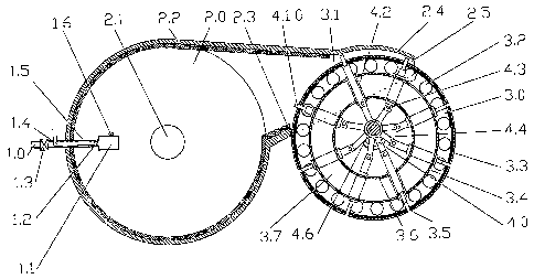
PARTS LIST
1.0 - fuel-air system
1.1- mixing chamber
1.2 - fuel injector (electronically actuated )
1.3 - air electro valve (electronically actuated )
1.4 - fuel tube
1.5-airtube
1.6 - sparker
2.0 - combustion chamber
2.1 - valve (chamber to atmosphere, electronically actuated)
2.2 - heat insulation
2.3 - lower lip
2.4 - upper lip
2.5 - end plates (two - one each side)
3.0 - drum
3.1- heat insulation
3.2 - side holes (a number of holes on each side - for the air to circulate,
between outermost
cylinder and intermediate cylinder, to do the hot air scavenging and cooling)
3.3 - outermost cylinder
3.4 - intermediate cylinder
3.5 - slots (a number of slots, equal with nuniber of plates)
3.6 - innermost cylinder
3.7 - end plates (two - one on each side)
3.8 - fane blade (a nuniber of fane blades - one for each hole on one side of
the drum, which
is the air flow producer between the outermost cylinder and intermediate
cylinder, for
cooling)
3.9 - bushing
4.0 - plates displacement system
4,1,0. - plates assembly (a number of plates assembly)
4.1.1-- plates body (a number of plates body)
4.1.2 - sliders (a number of sliders - two for each plate)
4.1.3 - reinforcements (a number of reinforcemtents)
4.2 - bushings (a number of bushings - two for each plate assembly)
4.3 - pins (a number of pins - two for each plate assembly)
4.4 - rods (a number of rods - two for each plate assembly)
4.5 - central shaft (which give the rotational axis for drum)
4,5.1 - cam center shaft
4.6 - eccentric shaft (which give the rotational axis for the plates)
4.7 - main rod (a number of main rods equal with one of the plate assembly
sliders)
4.8 - auxiliary rod (which ride on the nlain rod bushing)
CA 02612386 2007-12-17
WO 2006/133534 PCT/CA2005/001671
4.9 - stoppers
4.10 - electro solenoid (a number of electro solenoids - one for each plate
slider)
4.11 - connecting rod (witch connect the diametric opposite plate sliders, to
balance the
centrifugal forces)
4.11.1 - connecting system (used with cam center shaft)
4.12 - springs (a number of springs - on.e for each plate slider)
4.13 - rollers (a number of rollers - one for each plate slider)
4.14 - pistons (a number of pistons - one for each plate slider, can be for
air or oil)
4.15 - cylinders (a number of cylinders - one for each plate slider, can be
for air or oil)
5.0 - coupling member
6.0 - support system
6.1 - left side bearing block
6.2 - right side bearing block
6.3 - holding pin (holds the shaft fix, not to rotate)
7.0 - the system to realise an automatic continuous variable displacement
7.1 - cylinder (hydraulic actuated)
7.2--gears
7.3 - camshaft
7.4 - rack (are in mesh with the gears)
7.5 - bushing (where slide the rack)
7.6 - spring (keep the rack in position)
7.7 - bushings (are the rotational axes for cam shaft, 7.3)
7.8 - guide sliders (which is guiding the camshaft up and down in the guide
block, 7.9)
7.9 - guide blocks
7.10 - springs (which keep the camshaft, 7.3, in position)
7.11 - guide blocks (two - on the central shafts, 4.5)
7.12 - cams (two, on the camshaft, 7.19)
7.13 - cams (two, on the sliding camshaft, 7.18)
7.14 - rollers (a number of rollers - two for each plate assembly)
7.15 - rollers (two - one each side of the sliding camshaft, 7.18)
7.16 - springs (two - one each side of the sliding camshaft, 7.18, keep it in
position)
7.17 - guides (two - one each side of the sliding camshaft, 7.18)
7.18 - sliding camshaft
7.19 - camshaft
7.20 - pins
6
CA 02612386 2007-12-17
WO 2006/133534 PCT/CA2005/001671
DESCRIPTION
Reference is made to Fig. 1 which illustrates a continuous internal combustion
engine. The
engine comprises a combustion chamber, 2.0, which has a discharge passage,
gate, that
accesses the interior of the chamber. A fuel-air system, 1.0, delivers a
mixture of fuel and air
to the interior of the combustion chamber and then ignites the mixture,
producing rapidly
expanding combustion gases. A drum, 3.0, and plates and positioning system,
4.0, controls
escape of the combustion gases through the gate, converting the energy
contained in the
expanding gases into rotary motion of the drum. The coupling member, 5.0,
transfers the
power from the drum to the transmission, and the support system, 6.0, help
holding and
rotating the drum.
The fuel-air system comprises an outer tube, 1.5, through which air is
delivered, and an
inner tube, 1.4, through fuel is delivered. Air supply is controlled by an air
electro valve, 1.3,
electronically actuated, and fuel supply is controlled by a fuel injector,
1.2, electronically
actuated. The air and fuel is supplied just when the acceleration pQdal is
depressed and is
according with the position of the pedal. When the acceleration pedal is
depressed less, so
will be the air and fuel delivered, when the acceleration pedal is depressed
more, more air
and fuel will be delivered, and when the acceleration pedal is no depressed,
no air and fuel is
delivered. All this will be computer controlled. The air and fuel get mixed in
the mixing
chamber, 1.1, after that get ignited by the sparker, 1.6.
In the combustion chamber, 2.0, the burning of the fuel-air mixture take
place, also act like
a high pressure accumulator, where the pressure of the burning gases will be
determined by
the resistance forces, which is translated in torque resistance. So when the
resistance forces at
the wheals increase, the necessary torque increase, also in order to overcome
this resistance
torque, the pressure in the conibustion chamber increase. So the sizes of the
engine, plates,
displacement, (the height of the plates in the gate area multiplied by the
length of the plate,
so the area on which the pressure act in the gate area), and combustion
chamber will be so
calculated that the maximum pressure in the combustion chamber to be always
less than the
pressure in the air supply tank, to be possible to supply air for burning. For
example, if in the
air tank would be 150 PSI, the maximum pressure in the combustion chamber
should be 100
PSI. In order to reduce the heat loses, to increase the efficiency of the
engine, on the inside or
outside, of the combustion chanzber can be used a heat insulation, 2.2. In the
gate area the
combustion chamber will have an upper lip, 2.4, and in the area where the
combustion
chamber came in close proximity with the drum will liave a lower lip, 2.3. On
the sides, to
close the combustion chamber and the gate, the combustion chamber will have
the end plates,
2.5. Also will exist a valve, chamber to atmosphere, electronically actuated,
2.1. This valve
will get opened, automatically by the computer, when the acceleration pedal is
not press and
the driver want that the car to run by inertia, not to be braked by the engine
brake. Closing
the valve causes drag on the drum, because the drum when rotate by inertia and
no air-fuel is
supplied , create a vacuum , slowing operation of the engine When the
acceleration pedal is
press the computer automatically will close the valve, to be able to turn the
engine. The only
time when this valve is close, and the acceleration pedal is not press, will
be when the driver
want to use the engine brake, and will be actuated by pressing the brake pedal
when first
travel of the pedal will actuate the valve, 2.1, closing this gradually, for a
smooth brake, and
the last travel of the brake pedal will actuated gradually the conventional
brakes also. In this
way the necessary conventional brakes will be much smaller. All this will be
done by the
7
CA 02612386 2007-12-17
WO 2006/133534 PCT/CA2005/001671
computer, according with the rotational speed of the drum, so the speed of the
car, and
according with the position of the brake pedal, so the grade of brake wanted,
for a smooth
braking. The combustion chamber comprises also a support structure, not shown.
The drum, 3.0, has a rotational axis and a support structure comprising a set
of three
concentric metal cylinders centered about the rotational axis: an outermost
cylinder, 3.3, an
innermost cylinder, 3.6, and an intermediate cylinder, 3.4, located between
the outermost and
innermost cylinders. The cylinders are connected, bolted or other way, to a
pair of opposing,
circular end plates, 3.7, that maintain the concentric relationship of the
cylinders. A coupling
member, 5.0, which may be a flange, like shown, or inside spline type, or any
other way to
do the coupling. This coupling member realise the coupling between the drum
and
transmission. The manner in which the drum is supported for rotation and for
transfer of
rotary power will be adapted to suit any practical application.
The outermost cylinder defines a generally circular cylindrical outer surface.
A number of
slots, 3.5, are machined in the outer cylindrical surface, and in the end
plates, parallel and
radial to the drum rotational axis, central shaft, 4.5, and equally spaced
circumferentially
about the outer cylindrical surface. The outermost cylinder has a heat
insulation, 3.1, located
on the inside side of this cylinder, in order to stop the heat lose from the
combustion
chamber, to increase the efficiency and to avoid overheating of the
lubricating oil. Also in
order to dissipate the heat escaping through the spaces between the plates and
the sides of the
slots, and in order that this gas not to go inside the innermost cylinder,
3.6, where exist the
lubricating oil, between the outermost cylinder and intermediate cylinder , to
avoid the
overheating of the lubrication system, the end plates have in this area side
holes , 3.2 , on the
both sides, to leave the air to circulate, and on one side each hole has a
fane blade, 3.8, which
forces ambient air to circulate between the outermost cylinder and
intermediate cylinder, to
avoid overheating. The bushing, 3.9, is used here to be possible that the
drum, 3.0, to rotate
on the central shaft, 4.5. All the bushings which are used by the drum to
rotate on, will be
pressure oil lubricated. When necessary, when is used gasoline, diesel, or
other fuels which
give noxes when burn, will exist a secondary exhaust for this separate from
the conventional
exhaust. When is using natural gas or hydrogen where is not noxes of burning
this is not
necessary. The pressure in the combustion chamber is lower than at a
conventional engine,
the burning temperature is lower, thus will not exist noxes NOx, so much less
pollutions.
The plates positioning system, 4.0, is located inside the drum. A number of
plates, 4.1.0,
are associated with the slots in the drum. Displacement of the vanes is timed
by the
mechanical linkage. Each of the plates is retracted, below the outer surface
of the drum, in
close proximity to this, when is near the lower lip. The plate then extends
radially to a fully
extended orientation as exemplified in, Fig. 1. In the fully extended
orientation, which is
timed to occur when the vane reaches the entrance in the discharge passage,
gate, the tip of
the plate is in close proximity with the upper lip, and then obstructs the
discharge passage
against discharge of combustion gases. Because of the mechanical linkage
involved, the plate
remains only momentarily in its fully extended orientation and begins
gradually to retract
toward its retracted orientation. In this embodiment, using eccentric shaft,
the upper lip of the
drum extend and then contracts radially, outward and inward, in conformance to
the radial,
outward and inward, movement of the plates, so that the plates remain in close
proximity to
the upper lip, keeping the passage closed against any significant gas
transfer, for a period of
time sufficient to allow a succeeding plate to extend and come in the gate
area, so to close the
passage. This is true just for the case when is used eccentric sliaft to
realise the displacement
8
CA 02612386 2007-12-17
WO 2006/133534 PCT/CA2005/001671
of the plates. In all the other cases, using camshaft, electro solenoids, air
or hydraulic
cylinders, the trajectory in the gate area can be design to be perfect
circular. The big
advantage of this arrangement is that no compressed combustion gases are
exhausted without
the energy of this to be used, and also the passage length is as short as
possible, in order to
obtain the best efficiency for the engine. The plate comprises an elongate
rectangular body,
4.1.1, and a set of two parallel sliders, 4.1.2, attached to the body. In an
operative orientation,
as in Fig. 1, the sliders extend radially inward from the plate body toward
the rotational axis.
The plates can have, if necessary, reinforcement, 4.1.3, in order to increase
the rigidity. In all
cases, using eccentric shaft, camshaft, electro solenoids or cylinders, to
realise the
displacement of the plates, the distance between the two sliders, 4.1.2, will
be different for
each set of two plates, diametric opposite, in order to avoid touching of the
connecting rods,
4.11 , 4.11.1 , or because is used main rod , 4.7, and auxiliary xod , 4.8 ,
the distance between
the two sliders, 4.1.2, will be different for each plate, but always they will
be equal distant
from the each end of the plate. Each slider are sliding in one bushing, 4.2,
which constrain
the plate, through the sliders, to a radial movement, and is pressure oil
lubricated, is mounted
radially in the drum, relative to rotational axis, and secured one end to the
innermost
cylinder, and the opposite end to intermediate cylinder.
The plates are displaced in response to rotation of the drum. This are
obtaining, here, when
using an eccentric shaft, by using one rod, 4.4, for each slider, which
connect the slider to the
eccentric shaft, 4.6, and has the rotational axis the eccentric shaft, which
stay in fix position
by using the holding pin, 6.3, through the central shaft, 4.5, which is one
piece with the
eccentric shaft, 4.6. So when the drum is rotating with the rotational axis
the central shaft,
4.5, the plates are rotating with it, and the displacement of the plates are
constrained by the
rods which have the rotational axis the eccentric shaft, 4.6, to realise the
proper position of
the plates relative to the position of the drum. The position of the eccentric
shaft is so -
determined that in the gate area the lifting of the plates is maximum.
In order to realise the connection between the rods and plates sliders, are
used the pins, 4.3,
so the link can articulate here, when working.
Here in order to have less friction force, so less heat, especially at high
speed, I wanted to
balance the centrifugal forces and to reduce the relative motion of the rods
when working. I
managed to do this by using a main rod, 4.7, and auxiliary rods, 4.8, system,
like in Fig. 3. In
this case the auxiliary rod is riding on the main rod. There is one main rod
for each slider of
one plate, here two, and both main rods are connected to the sliders belonging
to the same
plate. The rest of the plates sliders are connected to the auxiliary rods
which are riding on the
main rods bushing. The stoppers, 4.9, can be used to keep the auxiliary rods
in position. Both
are oil pressure lubricated. In this way the main rod has a full rotation when
working, but the
centrifugal forces in the main rod bushing are almost balanced, because all
centrifugal forces
are acting on this bushing balancing each other. The auxiliary rods which take
all the
centrifugal forces will have in turn just move a fraction of the rotation,
just the relative
difference of position between the main and auxiliary rod, when working, which
is much less
than one full turn. In this way the friction, the heat, decreases
substantially, and also the
efficiency increase. This way to realise the displacement of the plates, using
eccentric shaft
can be used very well for high rpm, up to 30,000 rpm. All the other ways to
realise the
displacement of the plates, shown later, can be used for lower rpm, up to
10,000 rpm.
Other ways to realise the displacement of the plates are:
9
CA 02612386 2007-12-17
WO 2006/133534 PCT/CA2005/001671
- using a carnshaft , like in Fig. 10 , where the plates sliders will run on
the camshaft,
4.5.1, by using rollers, 4.13, and springs, 4.12, are used to keep the plate
in position. In this
case the engine is cheaper and is easier to realise a certain moving of the
plate, but at high
rpm the plate can start floating, damaging the engine, and also the engine is
losing power to
overcome the inertia of the moving plate, decreasing the efficiency. So this
way can be used
at lower rpm.
- using electro solenoids, 4.10, and springs, 4.12, like in Fig. 11. In this
case the engine is
more expensive, at high rpm the plate can start floating, and is losing energy
for the
necessary electricity to move the plate. The advantage would be that the
moving of the plate
is easy to control at lower rpm.
- using pistons, 4.14, and cylinders, 4.15, which can use air or oil pressure,
like in Fig.
12. In this case will have same advantages and disadvantages like using
electro
solenoids.
In all this three cases, the centrifugal forces can be balanced by using a
connecting rod,
4.11, Fig. 11 & 12, or the connecting system, 4.11.1, Fig. 10. This connecting
rods
connect two diametric opposite plates, reducing substantially the necessary
forces for
moving in position the plates by reducing the centrifugal forces of the two
plates, and
also can be used two electro solenoids or cylinders to move the system of two
plates, so
the necessary forces will be reduced and so the size of the devices.
The coupling member, 5.0, is used to transfer the torque from the drum to the
transmission. This can be flange type, spline, or any other possibility to
realise the torque
transfer.
The drum is hold and rotates using a support system, 6.0, which comprise a
left side
bearing block, 6.1, and a right side bearing block, 6.2, Fig. 3. In order to
realise the
proper displacement of the plates, the eccentric shaft or camshaft, need to be
hold in
proper position, and this can be realised by using a holding pin, 6.3, spline,
or any other
way to do this .
This engine can be very easy design to have automatically continuous variable
displacement. This can be realised by keeping fix the drum rotational axis,
while
changing the displacement of the plates and accordingly changing the position
of the
combustion chamber, in order to keep the close proximity between the plate and
upper lip
in the gate area. In order to have a direct relationship between movement of
the plates
azid the movement of the combustion chamber,l used a cam system, two
camshafts, 7.3,
for the combustion chamber, which each extend on the other side of the
combustion
chamber, so exist four cams, two on each camshaft, and a camshaft, 7.19, for
the sliding
camshaft, 7.18, and all linked by a rack, 7.4. The sliding camshaft, 7.18, is
connected to
the central shaft, 4.5, at the both ends through the V shaped sliding guides,
7.17, and
which is part of the sliding shaft. This guides, 7.17, slide in the V shaped
guide blocks,
7.11, which are part of the central shaft, 4.5, Because of this guides the
sliding camshaft,
7.18, is prevented from rotating, because also that the central shaft, 4.5, at
one end is kept
in fix position by the holding pin, 6.3, but can be moved up and down. This
can be
realised by rotating the camshaft, 7.19, which has two cams, 7.12, this cams
push the
sliding camshaft, 7.18, through the rollers, 7.15, and the pins, 7.20, which
are mounted on
the sliding camshaft, 7,18. Two springs, 7.16, on each side of the sliding
camshaft, 7.18,
keep this in position. The springs, 7.16, are mounted between the guides,
7.17, on the
sliding camshaft, 7.18, and the guide blocks, 7.11, on the central shaft, 4.5.
So according
CA 02612386 2007-12-17
WO 2006/133534 PCT/CA2005/001671
to the pressure in the combustion chamber, air or oil will actuate in the
cylinder, 7.1,
pushing the rack, 7.4, which on the other side has a spring, 7.6, and guide in
the bushing,
7.5, to keep the rack, 7.4 in position. The rack make possible that the
camshafts, 7.3 and
7.19, to move same rotational distance, through the gears, 7.2. The combustion
chamber
is push in position by the camshaft, 7.3, through the guide sliders, 7.8,
which slides in the
guide blocks, 7.9, and kept in position by the springs, 7.10. The camshafts
are rotating in
the bushings, 7.7. So when the rack, 7.4, is changing position according to
the
combustion chamber gasses pressure, which is according to resistance forces to
the car
wheels, this rack is rotating all the gears, 7.2, same angle, so the
camshafts, 7.3 and 7.19,
are rotating same angle, and because the cams on all this camshafts, 7.12, are
the same,
the movement of the combustion chamber and the sliding camshaft, 7.18, are
same. And
also because the plates are running on the cams, 7.13, which are part of the
sliding
camshaft, 7.18, through the rollers, 7.14, they will move the same. All this
will be
electronically controlled and actuated.
Reference is made to, Fig. 13, which diagrammatically illustrates how the air-
fuel
supply is done. An air pump, drive by the drum, is pumping the air into an air
tank. From
here air is supplied, through an air tube, using an electronically controlled
air valve, into
the mixing chamber. On the other hand, a fuel pump, drive by the drum, is
pumping fuel
in a fuel accumulator. From here fuel is supplied, through a fuel tube, using
an
electronically controlled fuel injector, into the mixing chamber, where is
mixed with the
air, and when the mixture caxne out of the mixing chamber into the combustion
chamber,
the sparker ignites the air-fuel mixture. This system can be design to obtain
the wanted
pressure in the mixing chamber and combustion chamber.
Reference is made to, Fig. 14, which diagrammatically illustrates how the drum
is
adapted to lubricate his rotational axis, mechanical linkage and also remove
the heat from
the linkage. More specifically, the drum can comprise an oil inlet and an oil
outlet, both
accessing the interior of the innermost cylinder which contains the central
shaft and
mechanical linkage. A pump in communication with the oil inlet and oil outlet
circulates
lubricating oil to the lubrication points, sliding bushings and rotational
bushings. An oil
cooler in circuit, removes heat from the lubricating oil. Can be used an oil
reservoir, or
can be used the innermost cylinder of the drum as reservoir. Also the pump can
be fitted
inside the drum, and also the drum to play the roll of oil cooler.
Reference is made to, Fig. 15, which diagrammatically illustrates how the
electronic
control can be done.
Input sensors can be used, like:
- combustion chamber pressure sensor, to monitor the pressure in the
combustion
chamber;
- drum rpm sensor, to monitor the drum rpm;
- acceleration pedal position sensor, to know the level of acceleration
desired;
- brake pedal position sensor, to know the level of brake desired;
- drum position sensor, used just when using electro solenoids, air or oil
cylinders,
when is necessary to know the position of the drum to actuate the displacement
means;
This is just an example, there can be any other sensors.
A processor, computer, get the signals from the sensors, process this inputs,
and
according with this control different systems of the engine, using actuators,
like:
11
CA 02612386 2007-12-17
WO 2006/133534 PCT/CA2005/001671
- air electro valve, to control the necessary air;
- fuel injector, to control the necessary fuel;
- valve, chamber to atmosphere, to control the position of this valve;
- electro solenoids or electro valves, for oil or air actuated cylinders, used
to
displace the plates, so controlling the position of the plates;
- cam system actuator to vary the displacement, by changing the oil or air
pressure
in the rack cylinder;
This is just an exa.mple, there can be any other actuators.
It will be appreciated that particular embodiments of the invention have been
described
and that modifications may be made therein without departing from the spirit
of the
invention or necessarily departing from the scope of appended claims.
The continuous internal combustion engine has many advantages, beside the
conventional internal combustion engine, these are:
= first and the most important is that the thermal efficiency of continuous
internal
combustion engine will be almost double than of a conventional internal
combustion
engine. The continuous internal combustion engine is losing power just through
leakings
in the gaps, which will be little because the gaps are little, and through
exhaust. Roughly
the loss in gaps will be less then 5% and in the exhaust about 20%, here
doesn't exist
conventional cooling system for combustion chamber, which is thermal
insulated, just an
oil cooling for the drum, roughly another 5% loss of power, so in this case
the thermal
efficiency would be about 70% which is almost double then for the conventional
internal
combustion engine, which is about 35%, and is much lower at low speed and high
speed.
Would be the most efficient internal combustion engine in the world. Because
jet engine
is less efficient than the internal combustion engine, even if is faster, and
rocket engine is
the fastest but the least efficient. The turbine engine will also be less
efficient, because
this is using the inertia of the burni.n.g gas, and continuous internal
combustion engine is
using the pressure of the burning gas, so is using all the energy of this gas.
The only
existent engine more efficient would be the fuel cell which transform the
hydrogen
directly in electricity, but seams having a big disadvantage, the fact that
for high power
this cells to produce enough electricity would need very big fuel cells, so
they use
batteries to store electricity when the necessary power is not high and to use
this when the
necessary power is higher. This increase the cost and weight of the car,
making it not
efficient for high power.
= because this type of engine has good efficiency from low rpm, about 200 rpm,
to very
high rpm, up to 30,000 rpm, in this case is no more necessary to have a
transmission with
many speeds, cold be enough just a speed reduction, and inversion of
rotational direction.
Would be enough just to use a torque converter, with centrifugal lock up,
coupled to the
engine, and this coupled to a simple planetarium speed reduction, with a back
up
possibility. So the start will be smooth without to lose power after get some
speed. In this
way all the system engine transmission would be very easy so very little
inertia, thus very
efficient acceleration and deceleration, making it very efficient for running
in the city.
Because this system is easy the vehicle frame will be easier so all the
vehicle will weight
less, thus increasing the overall efficiency of the system vehicle.
= continuous internal combustion engine has a much higher thermal efficiency
and also
niuch more constant on all range of rotational speed, beside the conventional
engine
which has a low efficiency at low or high rpm.
12
CA 02612386 2007-12-17
WO 2006/133534 PCT/CA2005/001671
= because is a very simple system, make it cheap for building, cheap
maintenance and
repair.
= this engine will have much less vibration, and,just when accelerate or
decelerate, at
constant rpm the engine will have almost no vibration. So the vehicle will run
much
smoother, so much better driver comfort.
= this engine at deceleration, when air and fuel supply is stopped, acts like
a very efficient
auxiliary engine brake. Because of this and that the vehicle is easier, the
necessary brake
system will be much lighter, so cheaper. To be possible not to brake the
vehicle when
wanted, the combustion chamber can have a gate, a valve to leave the air to
pass. This
valve will be actuated electronic.
= this engine, because the exhaust pressure pulsation is very low, will run
with much less
noise and vibration than the conventional engine.
= with this engine is possible that, when the acceleration pedal is not
depressed, to stop
complete the fuel and air supply, thus decreasing the fuel consumption.
= the pressure in combustion chamber, for this engine, is lower; so
temperature of burning
is lower, thus the exhaust noxes will be lower, NOx will not exist any more,
so will be
less noxes. Also when using gasoline fuel is no more necessary to use EGR
valve to
reduce burning temperature and NOx noxes, which also increase the engine
thermal
efficiency. So will have enhanced thermal efficiency.
= because continuous internal combustion engine has the torque much more
constant then
a conventional engine, the torque leverage is almost constant, is no more
necessary to
have a flywheel, or maybe a very small one for very big engines.
= the continuous internal combustion engine can be build from very small size,
but still
high torque, so high power, to very big size, with very high torque and power.
So the
continuous internal combustion engine can be used for almost all kind of
vehicle,
motorcycles, cars, flying cars, planes, boats, atomic submarines, of course
using the
steam instead of combustion gas, and maybe even for building much more
efficient space
shuttles.
Same invention can be used very well as an air pump. With the only differences
that the
drum will drive by an engine, will not exist fuel-air system, the combustion
chamber will
serve as discharge chamber and will be much smaller, and where been the fuel-
air supply will
be now a discharge valve connected to the air tank. So when the engine rotates
the drum, in
opposite direction than the engine, the air will be push into the discharge
chaniber through
the gate, pressure rise and open the discharge valve to fill the air tank.
This pump will be
very simple construction, very good efficiency, and also very reliable. Same
like the air
pump, with the only difference that the drum will have different rotational
direction and the
air will be supplied from an air tank, can be build a very efficient air
motor.
13