Sélection de la langue

Search

Sommaire du brevet 2618483 

Énoncé de désistement de responsabilité concernant l'information provenant de tiers

Une partie des informations de ce site Web a été fournie par des sources externes. Le gouvernement du Canada n'assume aucune responsabilité concernant la précision, l'actualité ou la fiabilité des informations fournies par les sources externes. Les utilisateurs qui désirent employer cette information devraient consulter directement la source des informations. Le contenu fourni par les sources externes n'est pas assujetti aux exigences sur les langues officielles, la protection des renseignements personnels et l'accessibilité.

Disponibilité de l'Abrégé et des Revendications

L'apparition de différences dans le texte et l'image des Revendications et de l'Abrégé dépend du moment auquel le document est publié. Les textes des Revendications et de l'Abrégé sont affichés :

  • lorsque la demande peut être examinée par le public;
  • lorsque le brevet est émis (délivrance).
(12) Brevet: (11) CA 2618483
(54) Titre français: REGLEUR DE FRICTION POUR SUPPORTS D'EQUILIBRAGE DE CHASSIS DE FENETRE
(54) Titre anglais: FRICTION ADJUSTER FOR WINDOW BALANCE CARRIERS
Statut: Accordé et délivré
Données bibliographiques
(51) Classification internationale des brevets (CIB):
  • E05F 03/16 (2006.01)
  • E05D 15/16 (2006.01)
  • E05F 03/22 (2006.01)
(72) Inventeurs :
  • ROBERTSON, JEFFREY CHARLES (Etats-Unis d'Amérique)
(73) Titulaires :
  • ASSA ABLOY FENESTRATION, LLC
(71) Demandeurs :
  • ASSA ABLOY FENESTRATION, LLC (Etats-Unis d'Amérique)
(74) Agent: BORDEN LADNER GERVAIS LLP
(74) Co-agent:
(45) Délivré: 2011-03-29
(22) Date de dépôt: 2008-01-17
(41) Mise à la disponibilité du public: 2009-07-17
Requête d'examen: 2008-01-17
Licence disponible: S.O.
Cédé au domaine public: S.O.
(25) Langue des documents déposés: Anglais

Traité de coopération en matière de brevets (PCT): Non

(30) Données de priorité de la demande: S.O.

Abrégés

Abrégé français

L'invention a trait à un dispositif actionnable permettant de régler le degré de friction d'un mécanisme de châssis de fenêtre. Le régleur de friction est muni d'une interface d'entraînement qui agit sur l'interface de réglage de friction asservie à l'interface du porteur, de telle sorte que dès que ce mécanisme est actionné en faisant tourner celui-ci dans une fente oblongue du porteur, son interface agit sur l'interface du régleur de friction et force un élément de réglage situé à l'arrière à appliquer graduellement une pression croissante sur la partie adjacente d'une cannelure de fenêtre.


Abrégé anglais

A carrier for a window sash having an actuatable friction adjuster. The friction adjuster has a carrier interface that interacts with a mating friction adjuster interface of the carrier such that the actuation of the friction adjuster by rotating it within an oblong slot in the carrier causes the carrier interface to interact with the friction adjuster interface and forces a rear portion of the friction adjuster into progressively increasing frictional contact with an adjacent portion of a window frame sash channel.

Revendications

Note : Les revendications sont présentées dans la langue officielle dans laquelle elles ont été soumises.


7
CLAIMS:
1. A friction adjuster for window balance carriers, comprising:
(a) a carrier for a window sash contained within a window sash frame channel;
(b) an actuatable friction adjuster for the carrier;
(c) wherein the friction adjuster includes a carrier interface, the carrier
interface
interacting with a mating friction adjuster interface of the carrier such that
actuation of the
friction adjuster causes the carrier interface to interact with the friction
adjuster interface so as
to force a portion of the friction adjuster into closer contact with a portion
of a window frame
channel to restrain the carrier from twisting and binding within the sash
frame channel during
vertical movement of the carrier within the channel.
2. The friction adjuster of claim 1, further comprising a manipulation
interface for use in
actuating said friction adjuster.
3. The friction adjuster of claim 2, wherein said manipulation interface is
adapted for use
with a manipulation device.
4. The friction adjuster of claim 1, wherein said carrier interface includes a
helically
stepped gear surface.
5. The friction adjuster of claim 1, wherein said friction adjuster interface
includes a
helically stepped gear surface.
6. The friction adjuster of claim 1, wherein the degree of frictional contact
between the
portion of the friction adjuster contacting the window frame channel and the
window frame
channel is adjustable.

8
7. The friction adjuster of claim 1, wherein a stepped gear configuration of
at least one of
the carrier interface and the friction adjuster interface allow the friction
adjuster to maintain
its position after actuation of the friction adjuster.
8. The friction adjuster of claim 1, wherein said friction adjuster is
initially molded as
part of and connected to said carrier and can be broken away from said
connections when it is
necessary to actuate the friction adjuster.
9. A carrier with friction adjuster, comprising:
(a) a carrier for a window sash contained within a window sash channel;
(b) an actuatable friction adjuster for the carrier having a manipulation
interface
for actuating said friction adjuster;
(c) wherein the friction adjuster includes a carrier interface, the carrier
interface
interacting with a mating friction adjuster interface of the carrier such that
actuation of the
friction adjuster causes the carrier interface to interact with the friction
adjuster interface so as
to force a portion of the friction adjuster into adjustable frictional contact
with a portion of a
window frame channel to restrain the carrier from twisting and binding within
the sash frame
channel during vertical movement of the carrier within the channel.
10. The carrier with friction adjuster of claim 9, wherein the degree of
contact between a
portion of the friction adjuster contacting the window frame channel and the
window frame
channel is adjustable.
11. The carrier with friction adjuster of claim 9, wherein said manipulation
interface is
adapted for use with a manipulation device.
12. The carrier with friction adjuster of claim 9, wherein said carrier
interface and the
friction adjuster interface include interfacing helically stepped gear
surfaces.

9
13. The carrier with friction adjuster of claim 9, wherein the stepped gear
configuration of
at least one of the carrier interface and the friction adjuster interface
allow the friction adjuster
to maintain its position after actuation.
14. The carrier with friction adjuster of claim 9, wherein said friction
adjuster is initially
molded as part of and connected to said carrier and can be broken away from
said connections
when it is necessary to actuate the friction adjuster.
15. A method for adjusting the frictional force between a carrier of a window
sash and a
sash channel of a window frame comprising the steps of.
(a) installing an actuatable friction adjuster within the carrier, wherein the
friction
adjuster has a carrier interface that is engagable with a friction adjuster
interface on the
carrier, the friction adjuster having a rotatable manipulation interface for
actuating the friction
adjuster;
(b) actuating the friction adjuster by use of a rotatable manipulation device
on the
manipulation interface to apply a desired amount of frictional force between
the carrier and an
adjacent portion of the sash channel to restrain the carrier from twisting and
binding within
the sash frame channel during vertical movement of the carrier within the
channel.
16. The method of claim 15, wherein the carrier interface includes a plurality
of helical
steps on each side of the manipulation interface that engage with mating
helical steps on the
friction adjuster interface upon actuation of the friction adjuster by the
manipulation device.
17. The method of claim 16, wherein with the continuing rotation of the
manipulation
device, the force between the friction adjuster interface of the carrier and
the carrier interface
of the friction adjuster progressively increases resulting in progressively
increasing friction
between the carrier and the sash channel.

Description

Note : Les descriptions sont présentées dans la langue officielle dans laquelle elles ont été soumises.

CA 02618483 2010-02-17
FRICTION ADJUSTER FOR WINDOW BALANCE CARRIERS
FIELD OF THE INVENTION
The present invention pertains to the field of window balance carriers. More
particularly, the invention pertains to a friction adjuster for such carriers.
DESCRIPTION OF RELATED ART
Window balance carriers are a common part of many window designs. They travel
in a carrier channel in the window frame and support a window sash for the
window.
Within the carrier channel they are connected to a balance for the window.
And, in the
case of pivoting window sashes, which can be pivoted out of the plane of the
window
frame for cleaning or other purposes, they are typically provided with locking
mechanisms. These locking mechanisms usually include members that are forced
tightly
against the inner walls of the channel when the sash is pivoted out of the
frame. This

CA 02618483 2008-01-17
2
serves to create a frictional grip between the carrier and the channel
preventing the carrier
from moving against the upward pull of the window balance even after the
window has
been pivoted out of the frame and/or removed.
In the usual case, the carrier has a generally rectangular horizontal cross-
section
and fits snugly albeit slidingly within the rectangular horizontal cross-
section of the frame
channel. This enables the carrier to slide up and down in the channel without
twisting,
binding or otherwise moving out of proper alignment within the channel.
However,
carriers and channels do not always fit together perfectly. Sometimes carriers
fit too
loosely within the channel. This, among other things, can allow the aforesaid
problems to
arise and interfere with carrier/window operation. Thus, it would be
advantageous to
provide a solution to this problem.
SUMMARY OF THE INVENTION
The carrier with friction adjuster of the invention includes, in its most
basic
embodiments, a carrier for a window sash, and an actuatable friction adjuster
for the
carrier. The friction adjuster includes a carrier interface which interacts
with a mating
friction adjuster interface of the carrier such that actuation of the friction
adjuster causes
the carrier interface to interact with the friction adjuster interface and
forces a rear portion
of the friction adjuster into greater frictional contact with a portion of a
window frame
channel. A manipulation interface is provided for use in actuating the
friction adjuster
using a screw driver or other simple tool.
In the preferred embodiments illustrated, the friction adjuster's carrier
interface
and the friction adjuster interface of the carrier use a system of mating
helical gear steps
such that upon the simple rotation of the friction adjuster via the
manipulation interface,
the friction adjuster is urged outward from the carrier to contact the window
frame with
increasing frictional force. Finally, the friction adjuster can ideally be
molded as part of
and connected to the carrier, and held in place by simple break-away
connections so that it
can be broken away from said connections for use when and if the carrier ever
needs
tightening in its frame channel.

CA 02618483 2008-01-17
3
BRIEF DESCRIPTION OF THE DRAWING
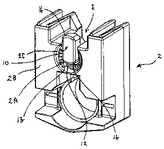
FIG. IA provides a perspective view of a friction adjuster of the invention in
the
process of being inserted into a carrier of the invention or, alternatively,
after being
removed from connection to the carrier. The carrier and friction adjuster are
shown from
the sash facing side.
FIG. 1 B provides a more detailed perspective view of the friction adjuster of
the
invention.
FIG. 2 provides a perspective view of the friction adjuster of the invention
as it is
being lowered into position into the carrier of the invention or,
alternatively, as it is being
removed from connection to the carrier. The carrier and friction adjuster are
shown from
the sash facing side.
FIG. 3A provides a perspective view of the friction adjuster of the invention
prior
to being separated from the carrier of the invention. The carrier and friction
adjuster are
shown from the frame facing side.
FIG. 3B provides a plane view of the friction adjuster of the invention prior
to
being separated from the carrier of the invention. The carrier and friction
adjuster are
shown from the frame facing side.
FIG. 4 provides a perspective view of the friction adjuster of the invention
in
position in the carrier of the invention, prior to being rotated. The carrier
and friction
adjuster are shown from the sash facing side.
FIG. 5 provides a perspective view of the friction adjuster of the invention
in
position in the carrier of the invention, after being slightly rotated. The
carrier and friction
adjuster are shown from the sash facing side.
FIG. 6 provides a cross-sectional view of the carrier and friction adjuster of
the
invention positioned in a frame channel.

CA 02618483 2008-01-17
4
FIG. 7A provides a plane view of the friction adjuster of the invention in
position
in the carrier of the invention, with both being appropriately positioned in a
frame channel.
The friction adjuster has been rotated. The carrier and friction adjuster are
shown from the
sash facing side.
FIG. 7B provides a partial cut-away perspective view of the friction adjuster
of the
invention in position in the carrier of the invention, with both being
appropriately
positioned in a frame channel. The friction adjuster has been rotated.
FIG. 8A provides a perspective view of the friction adjuster of the invention
in
position in the carrier of the invention, after being rotated. The carrier and
friction
adjuster are shown from the frame facing side.
FIG. 8B provides a second perspective view of the friction adjuster of the
invention in position in the carrier of the invention, after being rotated.
The carrier and
friction adjuster are shown from the frame facing side.
DETAILED DESCRIPTION OF THE INVENTION
The friction adjuster of the present invention is characterized by the use of
an
actuatable friction adjuster 1 for a carrier 2 placed in a frame channel 3, as
shown in Fig.
IA. The friction adjuster 1 includes a manipulation interface IA and a carrier
interface
1 B. The manipulation interface 1 A is on the same side of friction adjuster 1
as the carrier
interface 1 B and is used to manipulate the carrier interface 1 B against a
mating friction
adjuster interface 2A of carrier 2 (refer to Figs. 3A and 3B). As will be
explored in more
detail below, manipulation of the manipulation interface 1A causes the carrier
interface 2A
to interact with the friction adjuster interface 1 B so as to force a rear
portion 1 C of the
friction adjuster into varying degrees of frictional contact with a back
portion 3A of the
window frame channel 3 in which the carrier 2 is positioned (refer to Figs. 6
and 7B).
Ideally, manipulation interface IA is adapted for use with a manipulation
device,
e.g.-a common tool (such as a screwdriver 4), such that the friction adjuster
1 is actuated
by rotation as shown in the drawing figures. Thus, as shown in the sequence
illustrated in

CA 02618483 2008-01-17
Figs. 1 A, 2, and 4, friction adjuster 1 (which is shown in greater detail in
Fig. 1 B) can be
inserted into a carrier 2 positioned in the channel 3 of a window frame. It
can then be
rotated (as illustrated in FIG. 5) to varying degrees so as to bring rear
portion 1 C into
greater or lesser contact with back portion 3A of frame channel 3. (refer to
Fig. 6). This
5 not only creates a closer contact between rear portion 1C and back portion
3A, it forces
carrier front 2B into closer contact with the inside of frame channel 3
overhangs 3B (best
shown in Fig. 7B).
The present invention relies on the interaction between sets of matched,
interfacing
helically stepped gear surfaces. The friction adjuster interface 2A of carrier
2 has two
opposed sets of carrier helical steps 10, and the carrier interface IB of
friction adjuster 1
has two opposed sets of friction adjuster helical steps 11. As best seen in
Figs. 3A and 3B,
the two sets of carrier helical steps 10 start at "low" points 12 and increase
in "height" to
"high" points 13, with the high point of each set of steps 10 being adjacent
the low point
of the other set. Likewise, as best seen in Fig. 1 B, the two opposing sets of
friction
adjuster helical steps 11 start at "low" points 15 and increase in "height" to
"high" points
14, with the high point of each set of steps 11 being adjacent to the low
point of the other
set. Thus, when the friction adjuster 1 is rotated so that low points 12 and
15 are adjacent,
the friction adjuster 1 is only minimally engaged and minimally extends
backwards
towards back portion 3A. From this position it can be further turned through
intermediate
positions until it reaches a point where high points 13 and 14 are adjacent,
and it is fully
extended towards back portion 3A. In this manner, the present invention allows
the
effective size of carrier 2 to be adjusted as needed so that it better fits
into frame channel
3. In addition, the matched stepped gear configuration allows interface 1 to
retain the
position to which it is adjusted.
The two sets of friction adjuster helical steps 11 are positioned on outwardly
extending tabs 16 of friction adjuster 1 in keeping with its general oblong
shape. This
shape is advantageous as it allows the friction adjuster 1 to be mounted in
and/or to freely
slide into oblong slot 17 in carrier 2 without being engaged and to then be
turned so as to
engage and actuate the friction adjuster 1. In addition, it allows for easy
molding of the
friction adjuster 1 in oblong slot 17 (either above or adjacent its usual
point of
engagement) in a manner that allows it to be easily disconnected from the
carrier 2 and

CA 02618483 2008-01-17
6
used for its intended purpose. In keeping with this purpose, only light break-
away
connections 5 are provided between the friction adjuster 1 and the carrier 2
to facilitate its
usage for the aforesaid purposes.
However, many variations are possible without exceeding the scope of the
inventive concept described and patented herein. Accordingly, it is to be
understood that
the embodiments of the invention herein described are merely illustrative of
the
application of the principles of the invention. Reference herein to details of
the illustrated
embodiments is not intended to limit the scope of the claims, which themselves
recite
those features regarded as essential to the invention.
15

Dessin représentatif
Une figure unique qui représente un dessin illustrant l'invention.
États administratifs

2024-08-01 : Dans le cadre de la transition vers les Brevets de nouvelle génération (BNG), la base de données sur les brevets canadiens (BDBC) contient désormais un Historique d'événement plus détaillé, qui reproduit le Journal des événements de notre nouvelle solution interne.

Veuillez noter que les événements débutant par « Inactive : » se réfèrent à des événements qui ne sont plus utilisés dans notre nouvelle solution interne.

Pour une meilleure compréhension de l'état de la demande ou brevet qui figure sur cette page, la rubrique Mise en garde , et les descriptions de Brevet , Historique d'événement , Taxes périodiques et Historique des paiements devraient être consultées.

Historique d'événement

Description Date
Lettre envoyée 2024-03-14
Inactive : Certificat d'inscription (Transfert) 2024-03-14
Inactive : Transferts multiples 2024-03-07
Représentant commun nommé 2019-10-30
Accordé par délivrance 2011-03-29
Inactive : Page couverture publiée 2011-03-28
Préoctroi 2010-11-29
Inactive : Taxe finale reçue 2010-11-29
Un avis d'acceptation est envoyé 2010-06-02
Lettre envoyée 2010-06-02
Un avis d'acceptation est envoyé 2010-06-02
Inactive : Approuvée aux fins d'acceptation (AFA) 2010-05-27
Modification reçue - modification volontaire 2010-02-17
Inactive : Dem. de l'examinateur par.30(2) Règles 2009-10-23
Demande publiée (accessible au public) 2009-07-17
Inactive : Page couverture publiée 2009-07-16
Inactive : CIB attribuée 2009-02-03
Inactive : CIB en 1re position 2009-02-03
Inactive : CIB attribuée 2009-02-03
Inactive : Certificat de dépôt - RE (Anglais) 2008-02-27
Lettre envoyée 2008-02-27
Demande reçue - nationale ordinaire 2008-02-27
Exigences pour une requête d'examen - jugée conforme 2008-01-17
Toutes les exigences pour l'examen - jugée conforme 2008-01-17

Historique d'abandonnement

Il n'y a pas d'historique d'abandonnement

Taxes périodiques

Le dernier paiement a été reçu le 2011-01-11

Avis : Si le paiement en totalité n'a pas été reçu au plus tard à la date indiquée, une taxe supplémentaire peut être imposée, soit une des taxes suivantes :

  • taxe de rétablissement ;
  • taxe pour paiement en souffrance ; ou
  • taxe additionnelle pour le renversement d'une péremption réputée.

Les taxes sur les brevets sont ajustées au 1er janvier de chaque année. Les montants ci-dessus sont les montants actuels s'ils sont reçus au plus tard le 31 décembre de l'année en cours.
Veuillez vous référer à la page web des taxes sur les brevets de l'OPIC pour voir tous les montants actuels des taxes.

Titulaires au dossier

Les titulaires actuels et antérieures au dossier sont affichés en ordre alphabétique.

Titulaires actuels au dossier
ASSA ABLOY FENESTRATION, LLC
Titulaires antérieures au dossier
JEFFREY CHARLES ROBERTSON
Les propriétaires antérieurs qui ne figurent pas dans la liste des « Propriétaires au dossier » apparaîtront dans d'autres documents au dossier.
Documents

Pour visionner les fichiers sélectionnés, entrer le code reCAPTCHA :


Pour visualiser une image, cliquer sur un lien dans la colonne description du document. Pour télécharger l'image (les images), cliquer l'une ou plusieurs cases à cocher dans la première colonne et ensuite cliquer sur le bouton "Télécharger sélection en format PDF (archive Zip)" ou le bouton "Télécharger sélection (en un fichier PDF fusionné)".

Liste des documents de brevet publiés et non publiés sur la BDBC .

Si vous avez des difficultés à accéder au contenu, veuillez communiquer avec le Centre de services à la clientèle au 1-866-997-1936, ou envoyer un courriel au Centre de service à la clientèle de l'OPIC.


Description du
Document 
Date
(aaaa-mm-jj) 
Nombre de pages   Taille de l'image (Ko) 
Abrégé 2008-01-16 1 13
Description 2008-01-16 6 233
Revendications 2008-01-16 3 107
Description 2010-02-16 6 225
Revendications 2010-02-16 3 121
Dessin représentatif 2010-05-30 1 12
Dessins 2008-01-16 9 891
Certificat de dépôt (anglais) 2008-02-26 1 160
Accusé de réception de la requête d'examen 2008-02-26 1 177
Rappel de taxe de maintien due 2009-09-20 1 111
Avis du commissaire - Demande jugée acceptable 2010-06-01 1 167
Correspondance 2010-11-28 1 30