Sélection de la langue

Search

Sommaire du brevet 2618697 

Énoncé de désistement de responsabilité concernant l'information provenant de tiers

Une partie des informations de ce site Web a été fournie par des sources externes. Le gouvernement du Canada n'assume aucune responsabilité concernant la précision, l'actualité ou la fiabilité des informations fournies par les sources externes. Les utilisateurs qui désirent employer cette information devraient consulter directement la source des informations. Le contenu fourni par les sources externes n'est pas assujetti aux exigences sur les langues officielles, la protection des renseignements personnels et l'accessibilité.

Disponibilité de l'Abrégé et des Revendications

L'apparition de différences dans le texte et l'image des Revendications et de l'Abrégé dépend du moment auquel le document est publié. Les textes des Revendications et de l'Abrégé sont affichés :

  • lorsque la demande peut être examinée par le public;
  • lorsque le brevet est émis (délivrance).
(12) Demande de brevet: (11) CA 2618697
(54) Titre français: ENSEMBLE A PALONNIERS TELESCOPIQUES
(54) Titre anglais: A TELESCOPIC LIFTING APPARATUS
Statut: Réputée abandonnée et au-delà du délai pour le rétablissement - en attente de la réponse à l’avis de communication rejetée
Données bibliographiques
(51) Classification internationale des brevets (CIB):
  • B66F 13/00 (2006.01)
  • A61G 07/10 (2006.01)
  • B66F 03/00 (2006.01)
(72) Inventeurs :
  • LILJEDAHL, GUNNAR (Suède)
(73) Titulaires :
  • LIKO RESEARCH & DEVELOPMENT AB
(71) Demandeurs :
  • LIKO RESEARCH & DEVELOPMENT AB (Suède)
(74) Agent: MARKS & CLERK
(74) Co-agent:
(45) Délivré:
(22) Date de dépôt: 2008-01-15
(41) Mise à la disponibilité du public: 2008-07-19
Requête d'examen: 2009-01-16
Licence disponible: S.O.
Cédé au domaine public: S.O.
(25) Langue des documents déposés: Anglais

Traité de coopération en matière de brevets (PCT): Non

(30) Données de priorité de la demande:
Numéro de la demande Pays / territoire Date
0700121-7 (Suède) 2007-01-19

Abrégés

Abrégé anglais


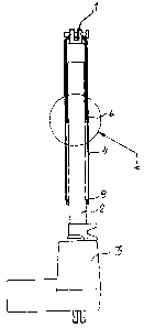
A lifting means includes at least two telescopically displaceable
lifting beams (1, 2), of which one (2) is connected to a
driving means (3) in order to displace the second lifting beam
(1) to and fro within said first lifting beam. A casing (4)
can be placed to surround both the lifting beams and rest
against these and surrounds both the lifting beams an essential
part when they are protruded. A pressure spring (5) is
placed within the casing (4) in order to displace the casing
(4) so it surrounds both the lifting arms (1, 2) when they are
in the protruded position in relation to each other whereby
the pressure spring rests against the end of the casing (4),
which end surrounds the displaceable lifting arm (1). A
support (6) for the second end of the pressure spring (5) is
attached on the fixed lifting beam (2).

Revendications

Note : Les revendications sont présentées dans la langue officielle dans laquelle elles ont été soumises.


6
CLAIMS
1. Arrangement at a lifting means consisting of at least two
telescopically displaceable lifting arms, of which one is con-
nected to a driving means in order to displace the second
lifting beam to and fro within the first lifting beam, whereby
a casing can be brought to surround both the lifting beams and
being extended a certain distance over both the lifting beams
in their protruded position, characterized in that a pressure
spring (5) is situated within the casing (4) and rests against
the casing (4) at the end, which surrounds the displaceable
lifting arm (1) and that a support (6) is attached on the
fixed lifting arm (2) for supporting the second end of the
pressure spring, which support (6) has a distance from the end
of the lifting beam (2), which distance corresponds to about
half of the length of the casing (4).
2. Arrangement according to claim 1, characterized in that
the end of the casing (4) which faces the driving means (3),
includes a ring (8), which slides against the outside of the
lifting beam (2) and that a corresponding support (7) is ar-
ranged at the second end of the casing and forms the support
for the end of the pressure spring (5).
3. Arrangement according to claim 2, characterized in that
the support (7) at the second end of the casing is in the form
of a cover (7).

Description

Note : Les descriptions sont présentées dans la langue officielle dans laquelle elles ont été soumises.


CA 02618697 2008-01-15
1
ARRANGENENTAT TELESCOPIC LIFTING BEAMS_
This invention relates to an arrangement at at least two tele-
scopically protrudable lifting beams, of which one is connec-
ted to a driving means in order to displace the second beam
to-and-fro in said first beam, whereby a casing can be brought
to surround both beams resting on them and extending a long
part of the beams.
Lifting beams of this type are used, e.g. within the medical
service for lifting means, when a person is being lifted from
a sitting position to a standing position or from one place to
another. Telescopic lifting beams of this kind are also used
for other lifting purposes for patients.
The lifting beams are normally loaded in their longitudinal
direction and they are designed to meet such a load. The lift-
ing beams can be driven hydraulically via gears or manually
using rope-driving means or with the help of a crank means.
It has now shown, e.g. within the irLedical service, that the
lifting beams unintentionally have been loaded by bending when
the telescopic beams are in their protruded position in rela-
tion to each other, which have lead to that the outer lifting-
beam has been bent in the area where it,protrudes out of the
outer end of the first lifting beam. The object of the inven-
tion is to increase the strength of the lifting beams when
they are in their protruded position and that this is accom-
plished by simple means, which are cheap. SE 516855 discloses
such a solution consisting of a casing, which can be displaced
on the beams so it covers e.g. half of the fixed beam and the
first half of the protrudable beam so that the casing also
takes up the bending stresses.

CA 02618697 2008-01-15
4 '
2
The object of the invention is to simplify the d.esign of the
means, which perform the displacement of the casing when the
movable beam is protruded for carrying out its lifting move-
ment. The characteristics of the invention are stated in the
following claim 1.
An embodiment of the invention will now be described by refe-
rence to the drawings.
Fig. 1 is hereby a partly longitudinal cross section of the
lifting arrangement, having both lifting arms in.retracted po-
sition.
Fig. 2 is a partly longitudinal cross section as in fig. 1,
but the movable lifting arms are in protruded position.
Fig. 3 is an enlarged cross section at the position a in fig.
1.
Fig. 4 is an enlarged part of the cross section at position B
in fig. 2.
Fig. 5 is a part of an enlarged cross section at position C in
fig. 2.
The arrangement shown in fig. 1 and 2 comprises a lifting beam
1, which is telescoping in a second lifting beam 2, being
fixed to a driving means 3 which displaces the first lifting
beam 1. The driving means 3 can be any known engine as e.g. an
hydraulic engine or a gear motor, which drives the lifting
beam 1 telescoping in the lifting beam 2. The lifting beams
are loaded when the lifting beam 1 is protruding out of the

CA 02618697 2008-01-15
3
lifting beam 2 in the position shown in fig. 2. As can be seen
from fig. 2, the lifting beams 1 and 2 are surrounded by a
telescopic pipe or casing 4, which is displaceable over the
two lifting beams 1 and 2. Fig. 1 shows the position of the
lifting beams in which the telescopic casing 4 is completely
displaced downwards over the fixed lifting beam 2. Fig. 2
shows the telescopic casing 4 being placed over the half
length of the lifting beam 1 and over the half length of the
lifting beam 2.
The displacement of the telescopic casing 4 from the position
shown in fig. 1 to the position shown in fig..2 is performed
by a pressure spring 5 which is located within the lifting
beam 2. The telescopic casing 4 can also be said to be a case
or casing. The end of the pressure spring 5 which faces the
driving means 3 rests on a support 6 which is attached about
on the middle of the lifting arm 2. The second end of the
pressure spring 3 is supported by a cover 7 on the upper end
of the telescoping casing 4. When the driving means 3 dis-
places the lifting beam 1 telescopically out of the lifting
beam 2, the pressure spring 5 will press the casing 4 upwards
to the position shown in fig. 2. The power of the pressure
spring 5 can be so adapted that the casing 4 will cover as
much of the lifting beam 1 as of the lifting beam 2 when the
lifting beam 1 is in its most protruded position. However, it
can alternatively be so arranged that the casing 4 in its
lower end, that is to say the end which is closest to the
lifting means, is a ring 8 which will rest against the support
6 when the casing 4 is in the position shown in fig. 2 by be-
ing displaced by the pressure spring 5. The length of the ca-
sing 4 shall advisably be half of the lifting beam 1 plus half
of the lifting beam 2 as shown in fig. 2. The ring 8 also acts
as a support between the casing 4 and the lifting arm 2, and

CA 02618697 2008-01-15
4
the cover 7 on the casing 4 is designed to act in the same way
in relation to the lifting beam 1. In the position of the
lifting beams shown in fig. 2, the casing 4 will take up ben-
ding forces on the lifting beams specifically within the area
where the lifting beam 2 is telescopically protruded out of
the lifting beam 2.
Fig. 3 shows a part of a longitudinal cross section at the
area A in fig. 1. This figure shows the support 6 which is
attached to the casing against which the lower end of the
pressure spring is resting.
Fig. 4 shows a longitudinal cross section of the lower part of
the casing in the position B in fig. 2. In this position the
casing has been displaced by the pressure spring 5 so far as
possible by that the pressure spring 5 has carried out a pres-
sure between the support 6 and the cover 7 of the casing 4.
Also, the support ring 8 is shown, which forms a support bet-
ween the lifting beam 2 and the casing 4. The ring may also
form a limitation for how far the casing 4 can be displaced
upwards on the lifting beam 2 by that the support 6 will come
to rest on the ring 8. The support 6 is thus firmly attached
to the inner side of the casing 4.
Fig. 5 shows a longitudinal cross.section of the upper part of
the casing 4 at a position C in fig. 2. It is hereby seen that
the pressure spring 5 rests on the cover 7 attached at the up-
per end of the casing 4.
There are alternative solutions within the scope of the inven-
tion as for instance the design of the supports, the design of
the cover and also the design of the support ring. The support
ring may be omitted by that the outer dimension of the lifting

CA 02618697 2008-01-15
arm 2 is adapted to the inner dimension of the casing in an
area below the pressure spring 5, that is to say in the area B
accordi-ng to fig. 2. The upper end of the casing can be de-
signed in another way and have a design similar to a ring in-
5 stead of a cover. It should also be noted that in the forego-
ing disclosure two lifting beams have been described but the
inventive idea also includes several lifting beams arranged
one after the other.

Dessin représentatif
Une figure unique qui représente un dessin illustrant l'invention.
États administratifs

2024-08-01 : Dans le cadre de la transition vers les Brevets de nouvelle génération (BNG), la base de données sur les brevets canadiens (BDBC) contient désormais un Historique d'événement plus détaillé, qui reproduit le Journal des événements de notre nouvelle solution interne.

Veuillez noter que les événements débutant par « Inactive : » se réfèrent à des événements qui ne sont plus utilisés dans notre nouvelle solution interne.

Pour une meilleure compréhension de l'état de la demande ou brevet qui figure sur cette page, la rubrique Mise en garde , et les descriptions de Brevet , Historique d'événement , Taxes périodiques et Historique des paiements devraient être consultées.

Historique d'événement

Description Date
Le délai pour l'annulation est expiré 2013-01-15
Demande non rétablie avant l'échéance 2013-01-15
Réputée abandonnée - omission de répondre à un avis sur les taxes pour le maintien en état 2012-01-16
Inactive : Approuvée aux fins d'acceptation (AFA) 2012-01-11
Modification reçue - modification volontaire 2011-09-28
Inactive : Dem. de l'examinateur par.30(2) Règles 2011-03-28
Lettre envoyée 2011-02-04
Exigences de rétablissement - réputé conforme pour tous les motifs d'abandon 2011-01-26
Réputée abandonnée - omission de répondre à un avis sur les taxes pour le maintien en état 2011-01-17
Lettre envoyée 2009-02-18
Exigences pour une requête d'examen - jugée conforme 2009-01-16
Requête d'examen reçue 2009-01-16
Toutes les exigences pour l'examen - jugée conforme 2009-01-16
Demande publiée (accessible au public) 2008-07-19
Inactive : Page couverture publiée 2008-07-18
Inactive : CIB en 1re position 2008-06-30
Inactive : CIB attribuée 2008-06-30
Inactive : CIB attribuée 2008-06-25
Inactive : Déclaration des droits - Formalités 2008-04-23
Inactive : Certificat de dépôt - Sans RE (Anglais) 2008-02-27
Demande reçue - nationale ordinaire 2008-02-27

Historique d'abandonnement

Date d'abandonnement Raison Date de rétablissement
2012-01-16
2011-01-17

Taxes périodiques

Le dernier paiement a été reçu le 2011-01-26

Avis : Si le paiement en totalité n'a pas été reçu au plus tard à la date indiquée, une taxe supplémentaire peut être imposée, soit une des taxes suivantes :

  • taxe de rétablissement ;
  • taxe pour paiement en souffrance ; ou
  • taxe additionnelle pour le renversement d'une péremption réputée.

Les taxes sur les brevets sont ajustées au 1er janvier de chaque année. Les montants ci-dessus sont les montants actuels s'ils sont reçus au plus tard le 31 décembre de l'année en cours.
Veuillez vous référer à la page web des taxes sur les brevets de l'OPIC pour voir tous les montants actuels des taxes.

Historique des taxes

Type de taxes Anniversaire Échéance Date payée
Taxe pour le dépôt - générale 2008-01-15
Requête d'examen - générale 2009-01-16
TM (demande, 2e anniv.) - générale 02 2010-01-15 2009-12-16
TM (demande, 3e anniv.) - générale 03 2011-01-17 2011-01-26
Rétablissement 2011-01-26
Titulaires au dossier

Les titulaires actuels et antérieures au dossier sont affichés en ordre alphabétique.

Titulaires actuels au dossier
LIKO RESEARCH & DEVELOPMENT AB
Titulaires antérieures au dossier
GUNNAR LILJEDAHL
Les propriétaires antérieurs qui ne figurent pas dans la liste des « Propriétaires au dossier » apparaîtront dans d'autres documents au dossier.
Documents

Pour visionner les fichiers sélectionnés, entrer le code reCAPTCHA :


Pour visualiser une image, cliquer sur un lien dans la colonne description du document. Pour télécharger l'image (les images), cliquer l'une ou plusieurs cases à cocher dans la première colonne et ensuite cliquer sur le bouton "Télécharger sélection en format PDF (archive Zip)" ou le bouton "Télécharger sélection (en un fichier PDF fusionné)".

Liste des documents de brevet publiés et non publiés sur la BDBC .

Si vous avez des difficultés à accéder au contenu, veuillez communiquer avec le Centre de services à la clientèle au 1-866-997-1936, ou envoyer un courriel au Centre de service à la clientèle de l'OPIC.


Description du
Document 
Date
(aaaa-mm-jj) 
Nombre de pages   Taille de l'image (Ko) 
Description 2011-09-27 7 271
Description 2008-01-14 5 190
Abrégé 2008-01-14 1 24
Dessins 2008-01-14 1 22
Revendications 2008-01-14 1 37
Dessin représentatif 2008-07-06 1 3
Revendications 2011-09-27 4 134
Certificat de dépôt (anglais) 2008-02-26 1 160
Accusé de réception de la requête d'examen 2009-02-17 1 176
Rappel de taxe de maintien due 2009-09-15 1 111
Courtoisie - Lettre d'abandon (taxe de maintien en état) 2011-02-03 1 172
Avis de retablissement 2011-02-03 1 164
Courtoisie - Lettre d'abandon (taxe de maintien en état) 2012-03-11 1 172
Correspondance 2008-02-26 1 14
Correspondance 2008-04-22 2 52
Taxes 2011-01-25 2 77