Note : Les descriptions sont présentées dans la langue officielle dans laquelle elles ont été soumises.
CA 02622364 2008-03-12
Specification
TITLE OF THE INVENTION
PIN HOLDER TYPE FASTENER
BACKGROUND OF THE INVENTION
Field of the Invention
The present invention relates to a pin holder type
fastener including a pin and a pin holder. Particularly
preferably, the invention is applied to a fastener of an
ornament, such as a tiepin, a brooch, a pierced earring or a
necklace, but it is also applied to a fastener of various kinds
of article, other than the ornament, of a comparatively small
size.
Description of the Related Arts
To date, it is conunon that a pin holder type fastener
in a bodily ornament such as, for example, a pierced earring,
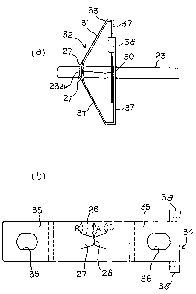
as shown in (a) in Fig. 1., has a structure in which a pin 1
having a peripheral groove 2 in a vicinity of a leading extreme
portion is inserted into a pin fastener (omitted from the
figure), and a holding member 3 of the pin fastener is moved.
into a position in which i_t locks into the peripheral groove
2, and is fixed. Then, as showri in (b) in Fig. 1, by causing
the holding member 3 to withdraw from the peripheral groove
2 by means of an appropriat.e operation, it is possible to
1
CA 02622364 2008-03-12
extract the pin 1 from the pin fastener.
In particular, in pin holder type fasteners of recent
years, there are many structures in which the holding member's
moving into and withdrawal from the peripheral groove of the
pin is carried out using a spring material having an elastic
deformation function. As a normal pin fastener is of a small
size, it is practical to simplify the structure of the fastener
by means of a pin holding mechanism using the spring material.
[Literature 1] JP-A-2002-336014
As a first related art, a fastener of an ear decoration
(a pierced earring) proposed in the heretofore mentioned
Literature 1 can be presented. The fastener, as shown in (a)
in Fig. 2, provides a hole 6 in a guide portion 5, which is
a central portion of a substrate 4. Then, a tubular guide piece
7 is fitted into the hole 6, and a pin is inserted via a through
hole 8 of the guide piece 7. Meanwhile, an elastic tab 9
accompanying a guide groove 10 is formed in a peripheral portion
of the substrate 4. The elastic tab 9 is bent gently to a rear
of the substrate 4, constructing a loop portion 11. That is,
as shown in (b) in Fig. 2, a structure is such that a pin 12
is inserted from the guide portion 5 side of the substrate 4,
causing the loop portion 11 to bite into a peripheral groove
13 thereof, and holding the pin 12.
Next, as a second related art, a pin fastener shown by
sectional views in (a) and (b) in Fig. 3 is also proposed. In
2
CA 02622364 2008-03-12
the pin fastener 14, a pair of holding members 16 made of a
material capable of an elastic deformation are housed inside
a cover 15, which overall is circular or elliptical. The
holding members 16, being configured approximately
symmetrically centered on a central pin insertion portion 17,
each include a pin holder arm 18 and a holding arm 19 of shapes
shown.
In a pinning condition, as shown in (a) in Fig. 3, each
of the holding arms 19 of the two holding members 16 pushes
the other holding member 16 in an opposite direction, as a
result of which, the pair of pin holder arms 18 is pushed in
a direction of the pin insertion portion 17. For this reason,
a pin (omitted from the figure) which is in the pin insertion
portion 17 is held by the pair of pin holder arms 18.
In a case of extracting the pin from the pin fastener
14, button portions 20 protruding into an exterior of the cover
15 from the holding members 16 are pressed into a direction
of the center. By so doing, as shown in (b) in Fig. 3, each
of the pair of pin holder arms 18, resisting a biasing force
of the holding arm 19, withdraws from the pin, and the pinning
condition is ended.
However, in the heretofore described first and second
related arts, the mechanism is such that the holding member
of the pin fastener (that is, the loop portion 11 in the first
related art, and the pin holder arms 18 in the second related
3
CA 02622364 2008-03-12
art) is brought into contact with the peripheral groove of the
pin from a radial direction (a right angle direction) . In the
case of this kind of mechanism, a pin insertion force (a force
necessary when inserting the pin into the pin fastener) and
a pin extraction force (a force necessary for extracting the
pin without a withdrawal operation of the holding member) are
basically of the same strength. Consequently, when setting
the pin insertion force small in consideration of an ease of
a pinning operation, the pin extraction force also becomes
smaller. As a result of this, due to, for example, the pierced
earring becoming caught on a hair or the like, there is a danger
of the pin falling out even though a pin extraction operation
has not been carried out. For this reason, it is not uncommon
that the pierced earring falls off without being noticed, and
that the pierced earring is lost.
Next, in the heretofore described first related art, it
is necessary that an extremely small tubular guide piece 7 is
manufactured, and that this is fitted into the hole 6 of the
substrate 4. Furthermore, it is necessary that the fitted
portion is fixed by means such as a welding. Also, in the
heretofore described second related art, it is necessary that
an extremely small pair of pin fasteners 14 of a complex shape
are accurately manufactured, and installed in the cover 15.
Consequently, an increase in their manufacturing cost and
installation cost is unavoidable.
4
CA 02622364 2008-03-12
SUMMARY OF THE INVENTION
An object of the invention is to provide a pin holder
type fastener with a small pin insertion force but a large pin
extraction force, with which moreover it is possible to easily
end a pinning condition with a simple operation. Another
object of the invention is to make a structure of this kind
of fastener simple, and to reduce a manufacturing cost thereof.
(First Aspect of the Invention)
A first aspect of the invention is a fastener including:
a pin holder; and a pin in which is provided a holding portion
formed by a peripheral groove, a depressed portion or a
protruding portion in a leading extreme portion vicinity, the
fastener holding the pin by locking a holding member of the
pin holder onto the holding portion of the pin, and ending a
pinning condition by causing the holding member to withdraw
from the holding portion, wherein
the pin holder, by bend forming a central portion of a
longitudinal direction of a thin plate-like spring material
into an acute angle or an arc, is formed to have a triangular
side view shape formed by an apex and a pair of inclining
portions on either side thereof,
as well as providing a pin holder hole for inserting a
pin in the apex, a pair of the holding members, of a length
CA 02622364 2008-03-12
such as to lock onto the holding portion of the pin inserted
into the pin holder hole, protrude from a peripheral portion
of a longitudinal direction in the pin holder hole, in the same
direction as the inclining portions, and furthermore,
by bend forming longitudinal direction extreme portions
of the pair of inclining portions in a direction along a bottom
edge of the triangular side view shape, stoppers are formed
against a pinning condition ending operation which causes an
elastic compression deformation of the triangular side view
shape of the pin holder.
In the fastener according to the first aspect, when
pinning the fastener, the pin is inserted into the pin holder
hole of the apex from a bottom edge side of the triangular shape
of the pin holder. At this time, the pin is inserted while
elastically deforming and pushing out the pair of holding
members protruding into the pin holder hole. Then, on the
holding portion reaching a protrusion position of the holding
members, the holding members lock onto the holding portion,
and the pinning is completed. In the event that the holding
portion of the pin is formed by the peripheral groove or the
depressed portion, as a small clicking sound is emitted when
the holding members move into the holding portion, it is
possible to easily confirm the completion of the pinning. As
the pair of holding members protrude in the same direction as
the inclining portions, a resistance to an insertion of the
6
CA 02622364 2008-03-12
pin is weak, and a resistance to an extraction of the pin which
is in the pinning condition is extremely strong. That is, a
pin insertion force is small, while a pin extraction force is
large.
When wishing to end the pinning condition, it is
sufficient that both extremes of the pair of inclining portions
of the pin holder are pinched between a thumb and an index finger,
and a force is applied in such a way as to reduce a space between
the extremes of the inclining portions (to cause an elastic
compression deformation of the triangular side view shape of
the pin holder) . By means of this operation, an elastic
deformation is brought about in such a way that the apex of
the pin holder bends more acutely, and the pair of holding
members protruding from the inclining portions are displaced
away from each other. Consequently, the holding members
withdraw from the holding portion, and it is possible to extract
the pin from the pin holder.
Then, as the stoppers are formed by bend forming the
longitudinal direction extreme portions of the pair of
inclining portions in the direction along the bottom edge of
the triangular side view shape, in a pinning condition ending
operation, it is sufficient that the compression deformation
of the pin holder is caused until the stoppers come into contact
with the pin. As a result of this, the pinning condition ending
operation becomes simple and reliable, on top of which it is
7
CA 02622364 2008-03-12
possible to effectively prevent damage to the apex due to
causing an excessive compression deformation of the pin holder,
and a deterioration of an elastic deformation capacity of the
apex.
(Second Aspect of the Invention)
A second aspect of the invention is a fastener including:
a pin holder; and a pin in which is provided a holding portion
formed by a peripheral groove, a depressed portion or a
protruding portion in a leading extreme portion vicinity, the
fastener holding the pin by locking a holding member of the
pin holder onto the holding portion of the pin, and ending a
pinning condition by causing the holding member to withdraw
from the holding portion, wherein
the pin holder, by bend forming a central portion of a
longitudinal direction of a thin plate-like spring material
into an acute angle or an arc, is formed to have a triangular
side view shape formed by an apex and a pair of inclining
portions on either side thereof,
as well as providing a pin holder hole for inserting a
pin in the apex, a pair of the holding members, of a length
such as to lock onto the holding portion of the pin inserted
into the pin holder hole, protrude from a peripheral portion
of a longitudinal direction in the pin holder hole, in the same
direction as the inclining portions, and furthermore
8
CA 02622364 2008-03-12
as well as forming a bottom edge portion by bend forming
one or both longitudinal direction extreme portions of the pair
of inclining portions in a direction along a bottom edge of
the triangular side view shape, a pin through hole for passing
the pin through is provided in a portion of the bottom edge
portion immediately below the pin holder hole.
In the second aspect, with the exception of effects and
benefits arising from the stoppers in the heretofore described
first aspect, the same effects and benefits as in the first
aspect can be acquired. Furthermore, there are the following
effect and benefit. That is, movements of the pin and the pin
holder, which are in the pinning condition, are mutually
restricted at two points, the pin holder hole of the apex and
the pin through holes of the bottom edge portions. For this
reason, as the pin holder does not wobble around the pin, the
fastener in the pinning condition does not wobble unsteadily.
(Third Aspect of the Invention)
A third aspect of the invention is a fastener wherein,
in the case of providing the bottom edge portion in both of
the longitudinal direction extreme portions of the inclining
portions, by means of ear tabs provided on one of the bottom
edge portions and bend formed in a direction of the other bottom
edge portion, the two bottom edge portions are mutually
restricted in a condition in which a relative sliding movement
9
CA 02622364 2008-03-12
in the longitudinal direction is possible.
In the third aspect, as the two bottom edge portions bend
formed from the pair of inclining portions are mutually
restricted by the ear tabs, the pin holder has a high structural
strength. Also, as the relative sliding movement of the two
bottom edge portions in the longitudinal direction is possible,
even when providing the ear tabs, there is no interference with
the pinning condition ending operation accompanying the kind
of elastic deformation of the pin holder previously described
in the first aspect.
(Fourth Aspect of the Invention)
A fourth aspect of the invention is a fastener including:
a pin holder; and a pin in which is provided a holding portion
formed by a peripheral groove, a depressed portion or a
protruding portion in a leading extreme portion vicinity, the
fastener holding the pin by locking a holding member of the
pin holder onto the holding portion of the pin, and ending a
pinning condition by causing the holding member to withdraw
from the holding portion, wherein
the pin holder, by bend forming a central portion of a
longitudinal direction of a thin plate-like spring material
into an acute angle or an arc, is formed to have a triangular
side view shape formed by an apex and a pair of inclining
portions on either side thereof, and
CA 02622364 2008-03-12
as well as providing a pin holder hole for inserting the
pin in the apex, turnback tabs protrude in a non-longitudinal
direction one from each of the pair of inclining portions, and
are bend formed in such a way as to overlap on a front surface
of the inclining portions (an exterior surface ofthetriangle),
and the holding member, of a length such as to lock onto the
holding portion of the pin inserted into the pin holder hole,
protrudes from the pair of turnback tabs, in the same direction
as the inclining portions, toward a centre of the pin holder
hole.
In the fastener according to the fourth aspect, in the
same way as in the case of the first aspect, it is possible
to easily manufacture the pin holder by processing a thin
plate-like spring material, on top of which, as a structure
is simple in comparison with a heretofore known pin holder,
it is possible to provide a low cost fastener.
Also, although the structure of the pin holder is
slightly complex in comparison with the case of the first aspect,
as it is not necessary to form the pin holder hole and the
holding member in the same portion of the thin plate-like spring
material, a process of forming the pin holder hole and the
holding member is easy.
(Fifth Aspect of the Invention)
A fifth aspect of the invention is the fastener in the
11
CA 02622364 2008-03-12
heretofore described fourth aspect wherein, by means of ear
tabs provided on non-longitudinal direction leading extreme
portions of the turnback tabs, and bend formed in a direction
of the inclining portions, the leading extreme portions of the
turnback tabs are brought into close contact with the inclining
portions.
As the turnback tabs bend formed in such a way as to
overlap on a front surface of the inclining portions include
the holding members, every time an operation of inserting the
pin in the pin holder is carried out, a force is received which
attempts to lift the turnback tabs up from the front surface
of the inclining portions. In the event that the turnback tabs
are lifted up from the front surface of the inclining portions,
it becomes impossible to realize a good pinning condition.
Consequently, by using the ear tabs to bring the turnback tabs
into close contact with the inclining portions, as in the fifth
aspect, it is possible to completely prevent this kind of
defect.
(Sixth Aspect of the Invention)
A sixth aspect of the invention is a fastener including:
a pin holder; and a pin in which is provided a holding portion
formed by a peripheral groove, a depressed portion or a
protruding portion in a leading extreme portion vicinity, the
fastener holding the pin by locking a holding member of the
12
CA 02622364 2008-03-12
pin holder onto the holding portion of the pin, and ending a
pinning condition by causing the holding member to withdraw
from the holding portion, wherein
the pin holder, by bend forming a central portion of a
longitudinal direction of a thin plate-like spring material
into an acute angle or an arc, is formed to have a triangular
side view shape formed by an apex and a pair of inclining
portions on either side thereof,
as well as providing a pin holder hole for inserting the
pin in the apex, turnback tabs protrude in a non-longitudinal
direction one from each of the pair of inclining portions, and
are bend formed in such a way as to overlap on a front surface
of the inclining portions (an exterior surface of the triangle),
and the holding member, of a length such as to lock onto the
holding portion of the pin inserted into the pin holder hole,
protrudes from the pair of turnback tabs, in the same direction
as the inclining portions, toward a centre of the pin holder
hole, and furthermore,
as well as forming a bottom edge portion by bend forming
one or both longitudinal direction extreme portions of the pair
of inclining portions in a direction along a bottom edge of
the triangular side view shape, a pin through hole for passing
the pin through is provided in a portion of the bottom edge
portion immediately below the pin holder hole.
In the sixth aspect, in addition to a point that the same
13
CA 02622364 2008-03-12
effects and benefits as in the heretofore described fifth
aspect can be acquired, there are the following effect and
benefit. That is, the movements of the pin and the pin holder,
which are in the pinning condition, are mutually restricted
at two points, the pin holder hole of the apex and the pin
through holes of the bottom edge portions. For this reason,
as the pin holder does not wobble around the pin, the fastener
in the pinning condition does not wobble unsteadily.
(Seventh Aspect of the Invention)
A seventh aspect of the invention is the fastener in the
heretofore described sixth aspect wherein, by means of ear tabs
provided on non-longitudinal direction leading extreme
portions of the turnback tabs, and bend formed in a direction
of the inclining portions, the leading extreme portions of the
turnback tabs are brought into close contact with the inclining
portions.
In the heretofore described sixth aspect, as the turnback
tabs bend formed in such a way as to overlap on a front surface
of the inclining portions include the holding members, every
time an operation of inserting the pin in the pin holder is
carried out, a force is received which attempts to lift the
turnback tabs up from the front surface of the inclining
portions. Then, in the event that the turnback tabs are lifted
up from the front surface of the inclining portions, it becomes
14
CA 02622364 2008-03-12
impossible to realize a good pinning condition. Consequently,
by using the ear tabs to bring the turnback tabs into close
contact with the inclining portions, as in the seventh aspect,
it is possible to completely prevent this kind of defect.
(Eighth Aspect of the Invention)
An eighth aspect of the invention is the fastener in the
heretofore described sixth aspect or seventh aspect wherein,
in the case of providing the bottom edge portion in both of
the longitudinal direction extreme portions of the inclining
portions, by means of ear tabs provided on one of the bottom
edge portions and bend formed in a direction of the other bottom
edge portion, the two bottom edge portions are mutually
restricted in a condition in which a relative sliding movement
in the longitudinal direction is possible.
In the eighth aspect, as the two bottom edge portions
bend formed from the pair of inclining portions are mutually
restricted by the ear tabs, the pin holder has a high structural
strength. As the relative sliding movement of the two bottom
edge portions in the longitudinal direction is possible, even
when providing the ear tabs, there is no interference with the
pinning condition ending operation accompanying the kind of
elastic deformation of the pin holder previously described in
the first aspect.
CA 02622364 2008-03-12
(Ninth Aspect of the Invention)
A ninth aspect of the invention is a fastener including:
a pin holder; and a pin in which is provided a holding portion
formed by a peripheral groove, a depressed portion or a
protruding portion in a leading extreme portion vicinity, the
fastener holding the pin by locking a holding member of the
pin holder onto the holding portion of the pin, and ending a
pinning condition by causing the holding member to withdraw
from the holding portion, wherein
the pin holder, by bend forming a central portion of a
longitudinal direction of a thin plate-like spring material
into an acute angle or an arc, is formed to have a triangular
side view shape formed by an apex and a pair of inclining
portions on either side thereof,
as well as providing a pin holder hole for inserting a
pin in the apex, a pair of the holding members, of a length
such as to lock onto the holding portion of the pin inserted
into the pin holder hole, protrude from a peripheral portion
of a longitudinal direction in the pin holder hole, in the same
direction as the inclining portions, furthermore,
as well as forming a bottom edge portion by bend forming
a longitudinal direction extreme portion of one of the pair
of inclining portions in a direction along a bottom edge of
the triangular side view shape, a pin through hole for passing
the pin through is provided in a portion of the bottom edge
16
CA 02622364 2008-03-12
portion immediately below the pin holder hole, and also,
as well as forming a stand-up portion by bend forming
a longitudinal direction extreme portion of the other of the
pair of inclining portions in a direction of the apex of the
triangle, a shelter member which surrounds a leading extreme
of the pin inserted into the pin holder hole is formed by bend
forming ear tabs provided at a leading extreme of the stand-up
portion.
In the fastener according to the ninth aspect, in the
same way as in the case of the first aspect, it is possible
to easily manufacture the pin holder by processing a thin
plate-like spring material, on top of which, as a structure
is simple in comparison with a heretofore known pin holder,
it is possible to provide a low cost fastener. Furthermore,
in the ninth aspect, there are the following effects and
benefits.
That is, as a first point, the movements of the pin and
the pin holder, which are in the pinning condition, are mutually
restricted at two points, the pin holder hole of the apex and
the pin through holes of the bottom edge portions. For this
reason, as the pin holder does not wobble around the pin, the
fastener in the pinning condition does not wobble unsteadily.
As a second point, as the stand-up portion is provided,
and the shelter member which surrounds the leading extreme of
the pin inserted into the pin holder hole is formed on the
17
CA 02622364 2008-03-12
stand-up portion, the leading extreme of the pin which is in
the pinning condition is housed inside the shelter member. As
a result of this, it is possible to prevent an accident such
as, handling the fastener carelessly, a sharp leading extreme
of the pin pricking a wearer's finger or skin.
(Tenth Aspect of the Invention)
A tenth aspect of the invention is a fastener including:
a pin holder; and a pin in which is provided a holding portion
formed by a peripheral groove, a depressed portion or a
protruding portion in a leading extreme portion vicinity, the
fastener holding the pin by locking a holding member of the
pin holder onto the holding portion of the pin, and ending a
pinning condition by causing the holding member to withdraw
from the holding portion, wherein
the pin holder, by bend forming a central portion of a
longitudinal direction of a thin plate-like spring material
into an acute angle or an arc, is formed to have a triangular
side view shape formed by an apex and a pair of inclining
portions on either side thereof,
as well as providing a pin holder hole for inserting the
pin in the apex, pin holder tabs are formed by bend forming
longitudinal direction extreme portions of the pair of
inclining portions in such a way as to overlap on a front surface
(an exterior surface of the triangle) or a rear surface (an
18
CA 02622364 2008-03-12
interior surface of the triangle) of the inclining portions,
and the holding member, of a length such as to lock onto the
holding portion of the pin inserted into the pin holder hole,
protrudes from a longitudinal direction extreme portion of the
pair of pin holder tabs, in the same direction as the inclining
portions, toward a centre of the pin holder hole.
In the fastener according to the tenth aspect, in the
same way as in the case of the first aspect, it is possible
to easily manufacture the pin holder by processing a thin
plate-like spring material, on top of which, as a structure
is simple in comparison with a heretofore known pin holder,
it is possible to provide a low cost fastener.
Also, although the structure of the pin holder is
slightly complex in comparison with the case of the first aspect,
as it is not necessary to form the pin holder hole and the
holding member in the same portion of the thin plate-like spring
material, a process of forming the pin holder hole and the
holding member is easy.
(Eleventh Aspect of the Invention)
An eleventh aspect of the invention is the fastener in
the heretofore described tenth aspect wherein, in the case of
bend forming the pin holder tabs in such a way as to overlap
on the front surface of the inclining portions, by means of
ear tabs provided in a non-longitudinal direction of the pin
19
CA 02622364 2008-03-12
holder tabs, and bend formed in a direction of the inclining
portions, the pin holder tabs are brought into close contact
with the inclining portions.
In the heretofore described tenth aspect, as the pin
holder tabs bend formed in such a way as to overlap on a front
surface of the inclining portions include the holding members,
every time an operation of inserting the pin in the pin holder
is carried out, a force is received which attempts to lift the
pin holder tabs up from the front surface of the inclining
portions. Then, in the event that the pin holder tabs are
lifted up from the front surface of the inclining portions,
it becomes impossible to realize a good pinning condition.
Consequently, by using the ear tabs to bring the pin holder
tabs into close contact with the inclining portions, as in the
eleventh aspect, it is possible to completely prevent this kind
of defect.
(Twelfth Aspect of the Invention)
A twelfth aspect of the invention is a fastener
including: a pin holder; and a pin in which is provided a holding
portion formed by a peripheral groove, a depressed portion or
a protruding portion in a leading extreme portion vicinity,
the fastener holding the pin by locking a holding member of
the pin holder onto the holding portion of the pin, and ending
a pinning condition by causing the holding member to withdraw
CA 02622364 2008-03-12
from the holding portion, wherein
the pin holder is configured of a spring member, and a
holder base including the holding member,
the spring member has a triangular side view shape formed
by an apex, having a shape of being bent into an acute angle
or an arc, and a pair of linear, inclining portions on either
side thereof, and also, includes a pin holder hole for inserting
a pin in the apex, and
by fixing the holder base on one or both of the pair of
inclining portions, holding members of the holding base
protrude in the same direction as the inclining portions, and
to a length such as to lock onto the holding portion of the
pin inserted into the pin holder hole.
In the ornament fastener according to the twelfth aspect,
it is not necessary to integrally form the spring member
configuring the pin holder and the holder base including the
holding members. Also, it being sufficient that a material
configuring the spring member is a material which can be
elastically deformed, it is not necessary to use a material
with which a bending process is possible. Due to these points,
a selection of the material and a design of the fastener are
relatively easy. Also, as the structure of the pin holder is
simple, it is possible to provide a low cost fastener.
When pinning the fastener, the pin is inserted into the
pin holder hole of the apex from a bottom edge side of the
21
CA 02622364 2008-03-12
triangular shape of the pin holder. At this time, the pin
exerts a force on the holding members protruding into the pin
holder hole which attempts to push the holding members out.
This force is transmitted to the spring material via the holder
base including the holding members and, by the spring member
bringing about a certain degree of deformation, the pin pushes
out the holding members, and is inserted into the pin holder
hole.
Then, on the pin holder portion reaching a protrusion
position of the holding members, the heretofore described
certain degree of deformation of the spring member is removed,
as a result of which, the leading extreme portions of the
holding members return to their original protrusion positions
and lock onto the pin holder portion, and the pinning is
completed. In the event that the pin holder portion is the
peripheral grooveorthe depressed portion, as a small clicking
sound is emitted when the holding members lock onto the holding
portion, it is possible to easily confirm the completion of
the pinning. As the holding members protrude in the same
direction as the inclining portions, a resistance to an
insertion of the pin is weak, and a resistance to an extraction
of the pin which is in the pinning condition is extremely strong.
That is, a pin insertion force is small, while a pin extraction
force is large.
When wishing to end the pinning condition, it is
22
CA 02622364 2008-03-12
sufficient that both extremes of the pair of inclining portions
of the spring member are pinched between a thumb and an index
finger, and a force is applied in such a way as to reduce a
space between the extremes of the inclining portions. By means
of this operation, an elastic deformation is brought about in
such a way that the apex of the spring member bends more acutely,
and the pair of holding members protruding from the inclining
portions are displaced away from each other. Consequently,
the holding members withdraw from the pin holder portion, and
it is possible to extract the pin from the pin holder.
(Thirteenth Aspect of the Invention)
A thirteenth aspect of the invention is a fastener
including: a pin holder; and a pin in which is provided a holding
portion formed by a peripheral groove, a depressed portion or
a protruding portion in a leading extreme portion vicinity,
the fastener holding the pin by locking a holding member of
the pin holder onto the holding portion of the pin, and ending
a pinning condition by causing the holding member to withdraw
from the holding portion, wherein
the pin holder is configured of a spring member, and a
holder base including the holding member,
the spring member has a triangular side view shape
composed of an apex, having a shape of being bent into an acute
angle or an arc, and a pair of linear, inclining portions on
23
CA 02622364 2008-03-12
either side thereof, and also, includes a pin holder hole for
inserting a pin in the apex,
by fixing the holder base on one or both of the pair of
inclining portions, holding members of the holding base
protrude in the same direction as the inclining portions, and
to a length such as to lock onto the holding portion of the
pin inserted into the pin holder hole, and furthermore,
longitudinal direction extreme portions of the pair of
inclining portions having bottom edge portions having a shape
of being bent in a direction along a bottom edge of the
triangular side view shape, a certain space is left between
leading extreme portions of the bottom edge portions, and a
notch portion is formed through which the pin inserted into
the pin holder hole can be passed.
With the ornament fastener according to the thirteenth
aspect, in addition to a point that the same effects and
benefits as in the heretofore described twelfth aspect can be
acquired, there are the following effect and benefit. That
is, the movements of the pin and the pin holder, which are in
the pinning condition, are mutually restricted at two points,
the pin holder hole of the apex of the spring member and the
bottom edge portions. For this reason, as the pin holder does
not wobble around the pin, the fastener in the pinning condition
does not wobble unsteadily.
24
CA 02622364 2008-03-12
BRIEF DESCRIPTION OF THE DRAWINGS
Fig. 1 shows a general structural principle of a pin
holder type fastener. Fig. 2 and Fig. 3 show a heretofore known
pin holder type fastener. (a) of Fig. 4 shows a pinning
condition of a fastener according to Example 1, (b) of Fig.
4 shows a pinning ending condition, and (c) of Fig. 4 shows
a template member of a pin holder. (a) of Fig. 5 shows a pinning
condition of a fastener according to Example 2, while (b) of
Fig. 5 shows a template member of a pin holder. (a) of Fig.
6 shows a pinning ending condition of the fastener according
to Example 2, while (b) of Fig. 6 shows a modification example
of the template member shown in (b) of Fig. S. Fig. 7 shows
the pinning condition of the fastener according to Example 2
by a perspective view. (a) of Fig. 8 shows an apex of the pin
holder in the pinning condition, (b) of Fig. 8 shows the apex
of the pin holder in the pinning ending condition, and (c) of
Fig. 8 shows the apex of the pin holder in a case in which a
shape of the template member differs. Fig. 9 shows a template
member of a pin holder according to Example 3. (a) of Fig.
shows a pinning condition of a fastener according to Example
3, while (b) of Fig. 10 shows a pinning ending condition thereof.
(a) of Fig. 11 shows a pinning condition of a fastener according
to Example 4, while (b) of Fig. 11 shows a template member of
a pin holder according to Example 4. (a) of Fig. 12 shows a
first template member of a pin holder according to Example 5,
CA 02622364 2008-03-12
while (b) of Fig. 12 shows a second template member. (a) of
Fig. 13 shows a bottom view showing a pin holder according to
Example 6 in a condition in which a spring member thereof is
spread flat, while (b) of Fig. 13 shows a positional
relationship of a pair of holder bases in (a) of Fig. 13. (a)
of Fig. 14 shows the pin holder according to Example 6 in a
pinning condition, while (b) of Fig. 14 shows the pin holder
according to Example 6 in a pinning ending condition. Fig.
15 shows a perspective view of the pin holder according to
Example 6 in the pinning condition. Fig. 16 shows a template
member of a pin holder according to Example 7, Fig. 17 shows
a pinning condition of a fastener according to Example 7 by
means of a perspective view, Fig. 18 shows a side view of Fig.
17, and Fig. 19 shows an ending condition of a pinning in Fig.
18. Fig. 20 shows a template member of a pin holder according
to Example 8, and Fig. 21 shows a pinning condition of a fastener
according to Example 8 by means of a perspective view. Fig.
22 shows a template member of a pin holder according to Example
9, and Fig. 23 shows a pinning condition of a fastener according
to Example 9 by means of a perspective view. Fig. 24 shows
a template member of a pin holder according to Example 10, and
Fig. 25 shows a pinning condition of a fastener according to
Example 10 by means of a perspective view.
Embodiments of the Invention
26
CA 02622364 2008-03-12
Next, a description will be given of embodiments for
implementing a first aspect to a thirteenth aspect of the
invention, including a best embodiment thereof.
[Overall Description of Fastener]
A fastener according to the invention is a pinning type
fastener configured of a pin holder and a pin provided with
a holding portion in a vicinity of an extreme. Then, holding
the pin by locking a holding member of the pin holder in the
holding portion of the pin, a pinning condition is ended by
withdrawing the holding member from the pin holding portion.
The pin holding portion is configured of a peripheral
groove, a depressed portion and a protruding portion. It is
not essential that the peripheral groove, which is the holding
portion, is provided around a whole circumference of the pin.
Also, a depth of the peripheral groove not being limited, in
the event that a locking strength of the holding member is
sufficiently high, taking also a frictional resistance into
account, it is acceptable that the peripheral groove is formed
extremely shallow, or to an extent that the peripheral groove
is barely noticeable. A shape of the depressed portion or
protruding portion, which are the holding portion, is not
limited as long as it is possible to lock the holding member.
It is particularly preferable that the fastener of the
invention is applied to a fastener of an ornament. With regard
27
CA 02622364 2008-03-12
also to various kinds of article, other than the ornament, of
a comparatively small size, for example, a toy or an everyday
article, it is possible to fasten parts thereof together by
providing the pin holder on one of them, and the pin on the
other. Furthermore, the fastener can also be used to fasten
these articles to a wall surface, board or the like by providing
the pin holder on one of them, and the pin on the other.
A kind of ornament on which the fastener according to
the invention can be used is not limited, as long as it is an
ornament furnished with a pin holder type fastener, but a tiepin,
a brooch, a pierced earring, a necklace and the like are
illustrated as being representative. In these kinds of
ornament, for example, attaching the pin to an ornamental
member side adorned with a jewel or the like, it is possible
to establish a method which holds the ornamental member with
the pin fastener. Also, as another attachment method, the
fastener can also be used as a joint of an electric wire or
an electric cable. In a saw or a cutting tool with a handle,
the fastener can also be used in a connection or the like of
the handle portion and a blade portion.
(Pin Holder according to First Aspect to Eleventh Aspect)
Although there is a large variety of embodiments of the
pin holder, any pin holder in the first aspect to the eleventh
aspect is configured using a thin plate-like spring material.
It is particularly preferable that the thin plate-like
28
CA 02622364 2008-03-12
spring material is capable of being bent, and is configured
by processing a single rectangular thin plate-like spring
material. In this case, as regards a manufacture of the pin
holder, a flat, rectangular, single thin plate-like spring
material is prepared, a pin holder hole and the holding member
are formed by, for example, performing a punching process,
after which, preferably, a necessary bending formation is
carried out accompanying a heat treatment. Consequently, as
it possible to manufacture using the single thin plate-like
spring material, an installation of a plurality of parts being
unnecessary as well as a structure of the pin holder being
simple, it is possible to provide a low cost fastener.
The heretofore described thin plate-like spring
material is made of a material having an elastic deformation
capacity. Although a spring steel such as brass or stainless
steel can of course be used, as precious metals such as gold
or platinum also have a certain elastic deformation capacity,
they can also be used. It is also possible to use a hard plastic
thin plate-like spring material.
A thickness of the thin plate-like spring material is
determined as appropriate, considering an extent of the elastic
deformation capacity of the spring material, an ease of the
bending process and the like. Although dimensions of the
rectangular thin plate-like spring material are basically
determined considering a size of a pin holder to be manufactured,
29
CA 02622364 2008-03-12
at the same time, vertical and horizontal dimensions for
forming a template member, to be described hereafter, are
necessary. Consequently, the vertical and horizontal
dimensions necessary for the thin plate-like spring material
may differ depending on an embodiment of the pin holder.
Although a method of processing the thin plate-like
spring material to manufacture the pin holder is not limited,
a particularly effective and preferable method consists of the
following first process and second process.
As the first process, the punching process is performed
on the thin plate-like spring material, forming the template
member (a flat, thin plate-like spring material having a
predetermined shape, necessary for manufacturing the pin
holder). It is also acceptable that the template member is
formed by an appropriate processing method other than the
punching process such as, for example, a process using a cutter.
As the second process, a necessary bending process is
performed on the template member, configuring the pin holder.
In the second process, in order to fix a shape of a bent portion,
it is preferable that the bending process is carried out while
doing the heat treatment. The bending process includes a
bending process of an apex common to each of the following
embodiments, a bending process of a stopper in a first
embodiment, a bending process of a bottom edge portion in a
second, fourth and fifth embodiment, a bending process of an
CA 02622364 2008-03-12
ear tab in the second to sixth embodiments, a bending process
of a turnback tab in the third and fourth embodiments, a bending
process of a stand-up portion in the fifth embodiment, and a
bending process of a pin holding tab in the sixth embodiment.
(Pin Holder According to Twelfth Aspect and Thirteenth Aspect)
A pin holder according to the twelfth aspect and
thirteenth aspect is configured of a spring member made of a
material capable of an elastic deformation, and a holder base
equipped with a holding member.
The constituent material of the spring material not being
limited, as long as it is a material capable of an elastic
deformation, it is also possible to use, for example, precious
metals, such as gold or platinum, which have a certain elastic
deformation capacity, as well as a spring steel such as brass
or stainless steel, but more preferably, a plastic material
or a rubber material (for example, a silicone rubber material) ,
which is an organic spring material, can be used.
The spring member has a triangular side view shape formed
by the apex, which has a shape of being bent at an acute angle
or in an arc, and a pair of linear, inclining portions on either
side of the apex, and also includes the pin holder hole in the
apex for inserting the pin. The holder base, which includes
a holding member for holding the pin, is fixed to one or both
of the pair of inclining portions. A constituent material of
the holder base is not limited but, while it is preferable that
31
CA 02622364 2008-03-12
it is made of a hard material, an elastic deformation capacity
is not necessarily required.
By fixing the holder base to the inclining portions of
the spring member, the holding member provided on the holding
base is configured in such a way as to protrude in the same
direction as the inclining portions, and at a length such as
to bite into the peripheral groove of the pin inserted into
the pin holder hole.
Herein, "fixing" the holder base to the inclining
portions of the spring member means to arrange in such a way
that the holder base, at least, does not move farther than its
fixing position toward an extreme of the inclining portions.
Although details of this kind of fixing method are not limited,
for example, as will be illustrated in embodiments and examples
to be described hereafter, as well as configuring the holder
base with a material with which a bending process is possible,
the turnback tab provided on the holder base is turned back
in such a way as to wrap around the inclining portions of the
spring member, and it is possible to bring an extreme of the
turnback tab into contact with a bend portion provided at the
extreme of the inclining portions. Furthermore, in the event
that the spring member is made of a comparatively soft plastic
material or rubber material, it is also possible to cause the
bent turnback tab to bite into the inclining portions of the
spring member. Furthermore, it is also acceptable to
32
CA 02622364 2008-03-12
configure appropriate locking means on each of the inclining
portions of the spring material and the holder base, which
interlock at the fixing position of the holder base, and
restrict a movement of the holder base toward the inclining
portions extreme.
[First Embodiment of Pin Holder]
In the first embodiment of the pin holder according to
the invention, as well as the pin holder being made of the thin
plate-like spring material, by bend forming a central portion
of a longitudinal direction of the thin plate-like spring
material into an acute angle or an arc, it has the triangular
side view shape formed by the apex and the pair of inclining
portions on either side thereof. Furthermore, a stopper is
formed by bend forming a longitudinal direction extreme of the
pair of inclining portions in a direction along a bottom edge
of the triangular side view shape. The stopper, when causing
an elastic compression deformation of the triangular side view
shape of the pin holder in a pinning condition ending operation,
functions as the stopper by coming into contact with the pin.
In this embodiment, although this can also be said of
the other embodiments, to be described hereafter, it is
possible to optionally select a bending angle of the apex as
necessary. For example, with a pin holder for a pierced
earring, it is preferable to arrange in such a way that, the
33
CA 02622364 2008-03-12
apex having a gentle bending angle of around 100 to 150 degrees,
the pair of inclining portions have a spread. Meanwhile, with,
for example, a pin holder for a necklace, it is preferable,
the apex having a sharp bending angle of around 40 to 70 degrees,
to form the pin holder slenderly.
In the apex, as well as providing the pin holder hole
for inserting the pin, a pair of holding members, of a length
such as to lock into a holding portion of the pin inserted into
the pin holder hole, protrude in the same direction as the
inclining portions from a peripheral portion of a longitudinal
direction in the pin holder hole.
[Second Embodiment of Pin Holder]
In the second embodiment of the pin holder according to
the invention too, as well as the pin holder being made of the
thin plate-like spring material, by bend forming the central
portion of the longitudinal direction of the thin plate-like
spring material into an acute angle or an arc, it has the
triangular side view shape formed by the apex and the pair of
inclining portions on either side thereof.
Then, in the apex, as well as providing the pin holder
hole for inserting the pin, the pair of holding members, of
a length such as to lock into the holding portion of the pin
inserted into the pin holder hole, protrude in the same
direction as the inclining portions f rom the peripheral portion
34
CA 02622364 2008-03-12
of the longitudinal direction in the pin holder hole.
Furthermore, as well as forming a bottom edge portion
by bend forming one or both longitudinal direction extremes
of the pair of inclining portions in the direction along the
bottom edge of the triangular shape of the pin holder, pin
through holes for passing the pin through are provided in the
bottom edge portion, in a portion immediately below the pin
holder hole.
More preferably, in the case of providing the bottom edge
portion in both of the longitudinal direction extremes of the
inclining portions, as previously described, by means of ear
tabs provided on one of the bottom edge portions, and bend
formed in a direction of the other bottom edge portion, the
two bottom edge portions restrain each other in a condition
in which a relative sliding movement is possible in the
longitudinal direction.
[Third Embodiment of Pin Holder]
In the third embodiment of the pin holder according to
the invention too, as well as the pin holder being made of the
thin plate-like spring material, by bend forming the central
portion of the longitudinal direction of the thin plate-like
spring material into an acute angle or an arc, it has the
triangular side view shape formed by the apex and the pair of
inclining portions on either side thereof.
CA 02622364 2008-03-12
Then, in the apex, as well as providing the pin holder
hole for inserting the pin, a turnback tab protruding in a
non-longitudinal direction from each of the pair of inclining
portions, and being bend formed in such a way as to overlap
on a front surface of the inclining portions (a triangular
exterior surface of the pin holder), a holding member, of a
length such as to lock into the holding portion of the pin
inserted into the pin holder hole, protrudes from the pair of
turnback tabs, in the same direction as the inclining portions,
toward a centre of the pin holder hole.
More preferably, ear tabs provided at a non-longitudinal
direction extreme of the turnback tabs are locked onto the
inclining portions by being bend formed in the direction of
the inclining portions, and the turnback tabs are brought into
close contact with the inclining portions by means of the ear
tabs.
[Fourth Embodiment of Pin Holder]
In the fourth embodiment of the pin holder according to
the invention too, as well as the pin holder being made of the
thin plate-like spring material, by bend forming the central
portion of the longitudinal direction of the thin plate-like
spring material into an acute angle or an arc, it has the
triangular side view shape formed by the apex and the pair of
inclining portions on either side thereof.
36
CA 02622364 2008-03-12
Then, in the apex, as well as providing the pin holder
hole for inserting the pin, the turnback tab protruding in a
non-longitudinal direction from each of the pair of inclining
portions, and being bend formed in such a way as to overlap
on the surface of the inclining portions (the triangular
exterior surface of the pin holder), the holding member, of
a length such as to lock into the holding portion of the pin
inserted into the pin holder hole, protrudes from the pair of
turnback tabs, in the same direction as the inclining portions,
toward the centre of the pin holder hole.
Furthermore, as well as forming the bottom edge portion
by bend forming one or both longitudinal direction extremes
of the pair of inclining portions in the direction along the
bottom edge of the triangular side view shape of the pin holder,
the pin through hole for passing the pin through is provided
in the bottom edge portion, in the portion immediately below
the pin holder hole.
More preferably, the ear tabs provided at the non-
longitudinal direction extreme of the turnback tabs are locked
onto the inclining portions by being bend formed in the
direction of the inclining portions, and the turnback tabs are
brought into close contact with the inclining portions by means
of the ear tabs.
More preferably still, in the case of providing the
bottom edge portion in both of the longitudinal direction
37
CA 02622364 2008-03-12
extremes of the inclining portions, as previously described,
by means of the ear tab provided on one of the bottom edge
portions, and bend formed in the direction of the other bottom
edge portion, the two bottom edge portions restrain each other
in the condition in which the relative sliding movement is
possible in the longitudinal direction.
[Fifth Embodiment of Pin Holder]
In the fifth embodiment of the pin holder according to
the invention too, as well as the pin holder being made of the
thin plate-like spring material, by bend forming the central
portion of the longitudinal direction of the thin plate-like
spring material into an acute angle or an arc, it has the
triangular side view shape composed of the apex and the pair
of inclining portions on either side thereof.
Then, in the apex, as well as providing the pin holder
hole for inserting the pin, the pair of holding members, of
a length such as to lock into the holding portion of the pin
inserted into the pin holder hole, protrude in the same
direction as the inclining portions f rom the peripheral portion
of the longitudinal direction in the pin holder hole.
Furthermore, forming the bottom edge portion by bend
forming the longitudinal direction extreme of one of the pair
of inclining portions in the direction along the bottom edge
of the triangular side view shape of the pin holder, the pin
38
CA 02622364 2008-03-12
through hole for passing the pin through is provided in the
bottom edge portion, in the portion immediately below the pin
holder hole.
Also, as well as forming the stand-up portion by bend
forming the longitudinal direction extreme of the other of the
pair of inclining portions in a direction of the apex of the
triangle of the pin holder, a shelter member, which surrounds
a leading extreme of the pin inserted into the pin holder, is
formed by bend forming an ear tab provided at a leading extreme
of the stand-up portion.
[Sixth Embodiment of Pin Holder]
In the sixth embodiment of the pin holder according to
the invention too, as well as the pin holder being made of the
thin plate-like spring material, by bend forming the central
portion of the longitudinal direction of the thin plate-like
spring material into an acute angle or an arc, it has the
triangular side view shape formed by the apex and the pair of
inclining portions on either side thereof.
Then, in the apex, as well as providing the pin holder
hole for inserting the pin, pin holder tabs being formed by
bend forming the longitudinal direction extremes of the pair
of inclining portions in such a way as to overlap on the front
surface (the triangular exterior surface of the pin holder)
or rear surface (a triangular interior surface of the pin
39
CA 02622364 2008-03-12
holder) of the inclining portions, the holding member, of a
length such as to lock into the holding portion of the pin
inserted into the pin holder hole, protrudes from a
longitudinal direction extreme of the pair of pin holder tabs,
in the same direction as the inclining portions, toward the
centre of the pin holder hole.
More preferably, in the case of bend forming the pin
holder tabs in such a way as to overlap on the front surface
of the inclining portions, by bend forming ear tabs provided
at a non-longitudinal direction extreme of the pin holder tabs
in the direction of the inclining portions, the pin holder tabs
are brought into close contact with the inclining portions by
means of the ear tabs.
[Seventh Embodiment of Pin Holder]
In a seventh embodiment of the pin holder according to
the invention, the pin holder is configured of the spring member,
and the holder base including the holding member.
The spring member having the triangular side view shape
formed by the apex, which has a shape of being bent at an acute
angle or in an arc, and the pair of linear, inclining portions
on either side of the apex, and also including the pin holder
hole in the apex for inserting the pin, by the holder base being
fixed to one or both of the pair of inclining portions, the
holding member of the holder base is configured in such a way
CA 02622364 2008-03-12
as to protrude in the same direction as the inclining portions,
and to a length such as to lock into the holder portion of the
pin inserted into the pin holder hole.
More preferably, furthermore, the longitudinal
direction extremes of the pair of inclining portions having
bottom edge portions of a shape of being bent in the direction
along the bottom edge of the triangular side view shape, a
certain space is left between leading extremes of the bottom
edge portions, and a notch portion is formed through which the
pin inserted into the pin holder hole can pass.
EXAMPLES
Next, a description will be given, based on the drawings,
of examples of the invention. A technical scope of the
invention is not limited to the following examples.
[Example 1]
(Manufacturing Process and Configuration of Example 1)
As shown in Fig. 4, a fastener 21 includes a pin holder
22 and a pin 23.
(c) of Fig. 4 shows a template member 24 for manufacturing
the pin holder 22. The template member 24 is formed by
performing a punching process or other appropriate process on
a rectangular, thin plate-like spring material, with which a
bending process is possible and which has an elastic
41
CA 02622364 2008-03-12
deformation capacity. A central portion 25 (a portion
surrounded by a broken line) of the template member 24 is a
portion which forms a pin holder hole. In the central portion
25, by providing notches 26 of a certain shape, a pair of holding
members 27 heading along a longitudinal direction of the
template member 24 are formed in a shape wherein a width
gradually becomes less heading toward a leading extreme.
Although forming the holding members 27 with this kind of shape
has an important meaning with regards to design, this will be
described hereafter in Example 2.
An accurately calculated and designed small space 28 is
cut away between leading extremes of the pair of holding members
27. In other words, a shape is such that the pin holder hole
is formed in the central portion 25, the pair of holding members
27 protrude toward the central portion from a peripheral
portion of a longitudinal direction in the pin holder hole,
and the space 28 is left between the leading extremes of the
holding members 27.
The central portion 25 of this kind of template member
24 is bend processed into an arc, as shown in (a) of Fig. 4.
At this time, it is preferable that the bending shape is fixed
by carrying out a heat treatment. However, the pair of holding
members 27 are not bent. It is also acceptable that both
extremes of the longitudinal direction of the template member
24 are also bent back along broken lines 29. It is also
42
CA 02622364 2008-03-12
acceptable, in order to facilitate the bending back, to put
a shallow, groove-shaped notch in the broken line 29 portions.
The pin holder 22 formed in this way being made of a single
rectangular, thin plate-like spring material, the central
portion of the spring material is made an apex 30 bend formed
into an arc, and the pin holder 22 has a triangular side view
shape including a pair of inclining portions 31 on either side
of the apex 30. The apex 30 bend formed into an arc has a shape
wherein the pair of holding members 27 protrude from the
peripheral portion of the longitudinal direction in the pin
holder hole. As the pair of holding members 27 are not bend
processed, they protrude in the same direction as the inclining
portions. When the pin 23 is inserted into the pin holder hole,
the pair of holding members 27 protrude to a length such as
to bite into a peripheral groove 23a of the pin.
(Using Condition of Example 1)
The fastener 21 according to Example 1 is used in the
following way. That is, when pinning the fastener 21, the pin
23 is inserted from a bottom edge of the triangular shape of
the pin holder 22 into the pin holder hole of the apex 30. At
this time, the pin 23 is inserted while elastically deforming
the pair of holding members 27 protruding into the pin holder
hole, and pushing them out to an exterior. As the pair of
holding members 27 protrude in the same direction as the
inclining portions 31, they do not exhibit a strong resistance
43
CA 02622364 2008-03-12
to the heretofore described insertion of the pin. Then, on
the peripheral groove 23a of the pin 23 reaching a protrusion
position of the holding members 27, the holding members 27
elastically return to an original shape and move into the
peripheral groove 23a of the pin 23, and the pinning is
completed.
As a small clicking sound is emitted when the holding
members 27 moves into the peripheral groove 23a of the pin 23,
it is possible to easily confirm the completion of the pinning.
For this reason, it is possible to reliably pin the fastener
21. In the fastener 21 which is in the pinning condition, in
a condition in which the holding members 27 protrude in a
direction opposite to a direction in which the pin 23 comes
out, the pin 23 will not come out of the pin fastener 22 as
the condition stands, as the holding members 27 are biting into
the peripheral groove 23a. For this reason, even in the event
that the pin holder 22 or pin 23 becomes caught on, for example,
a hair or other material, the pinning condition is maintained,
and a problem such as a loss due to an ornament falling off
does not occur.
When wishing to end the pinning condition of the fastener
21, extremes of the pair of inclining portions 31 of the pin
holder 22 are pinched between, for example, a thumb and an index
finger, and a force is applied in directions of arrows
(directions of reducing a space between the extremes of the
44
CA 02622364 2008-03-12
inclining portions 31) shown in (b) of Fig. 4. By means of
this operation, as shown in (b) of Fig. 4, an elastic
deformation is brought about in such a way that the apex 30
of the pin holder 22 bends more acutely.
This aspect is illustrated in further detail in Fig. 8.
(a) of Fig. 8 shows the apex 30 in the pinning condition, while
(b) of Fig. 8 shows the apex 30 when ending the pinning condition.
As shown in (b) of Fig. 8, by bringing about an elastic
deformation in such a way that the apex 30 of the pin holder
22 bends more acutely, the pair of holding members 27 are
displaced away from each other. Consequently, the pair of
holding members 27 withdraw from the peripheral groove 23a of
the pin 23. For this reason, the pin 23 easily comes out of
the pin holder 22.
[Example 2]
(Manufacturing Process and Configuration of Example 2)
A fastener 32 according to Example 2 includes a pin holder
33 and the same pin 23 as in the case of Example 1. The pin
holder 33 is manufactured using a template member 34 shown in
(b) of Fig. 5. The template member 34 is made of a material
with which a bending process is possible, and which has an
elastic deformation capacity.
In the template member 34, by providing the notches 26
in a central portion in the same way as the previously described
CA 02622364 2008-03-12
template member 24, the pair of holding members 27 and the space
28 are formed. However, in the template member 34, extension
portions 35 for configuring bottom edge portions 37, to be
described hereafter, are provided at either extreme of a
longitudinal direction. In the extension portions 35, pin
through holes 36 are formed in portions which come immediately
below the apex 30 when configuring the bottom edge portions
37. As the pin through holes 36 are formed in long ovals in
a left-right direction of the figure, the inserted pin 23 can
move relatively in the left-right direction.
By bend processing the central portion of the
longitudinal direction of this kind of template member 34 into
an arc, as shown in (a) of Fig. 5, the apex 30 and the pair
of inclining portions 31 are formed. Furthermore, by bend
processing the extension portions 35, which are the extremes
of the inclining portions 31, along broken lines of (b) of Fig.
5, a mutually overlapping pair of bottom edge portions 37 are
formed. It is also acceptable, in order to facilitate the
bending back, to put a shallow, groove-shaped notch in the
broken line portions. The previously described pin through
holes 36 are positioned in portions of the bottom edge portions
37 immediately below the apex 30.
Also, each leading extreme of the pair of bottom edge
portions 37 is of a length such that it does not reach a base
of the other bottom edge portion 37. Consequently, as shown
46
CA 02622364 2008-03-12
in (a) of Fig. 6, when ending a pinning condition of the fastener
32, they do not constitute an obstacle to an operation causing
an elastic deformation of the apex 30 of the pin holder 33 in
such a way that it bends more acutely.
As shown in (b) of Fig. 5, ear tabs 38 are formed at a
leading extreme of one of the extension portions 35. After
forming the bottom edge portions 37 in the way heretofore
described, the ear tabs 38 are bend formed in a direction of
the other bottom edge portion 37. Although the same also
applies to ear tabs shown in each of the following examples,
it is also acceptable, in order to facilitate a bending back
along depicted broken lines, to put a shallow, groove-shaped
notch in the ear tabs 38. By means of the bending formation
of the ear tabs 38, the two bottom edge portions 37 restrain
each other in a condition in which a relative sliding movement
is possible in a longitudinal direction.
Although also common to the previously described Example
1 and to each of the examples to be described hereafter,
although it is also acceptable that the pair of holding members
27 in this Example 2 are of a shape wherein they have the same
width from a base to a tip, it is particularly preferable that
they are of a shape wherein the width gradually becomes less
heading toward the tip, as shown in (b) of Fig. 5.
In the event that the pair of holding members 27 are of
the shape shown in (b) of Fig. 5, a portion corresponding to
47
CA 02622364 2008-03-12
the apex 30 in the template member 34 (a portion indicated by
a width A) is of a greater width than base portions of the
holding members 27 in the template member 34 (portions
indicated by widths B) . For this reason, when forming the apex
30 of the pin holder 33 by bend processing the template member
34, a bending force does not concentrate in the portion
indicated by the width A. Consequently, as shown in (b) of
Fig. 8, it is possible to bend a whole, from the portion
indicated by the width A as far as the portions indicated by
the widths B on either side thereof, evenly in a gentle arc.
The apex 30 having this kind of bending shape exhibits a
superior durability in response to a repetition of a pinning
condition ending operation which causes an elastic compression
deformation of a triangular side view shape of the pin holder
33.
In the event that, provisionally, the pair of holding
members 27 are of the shape wherein they have the same width
from the base to the tip, the bending force in the bend
processing of the template member 34 concentrates in the
portion corresponding to the apex 30, and this portion is bent
into a sharp arc. For this reason, as shown in (c) of Fig.
8, a distance W between the tips of the pair of holding members
27 is small in comparison with the case of (b) of Fig. 8, to
be described hereafter. That is, in order to withdraw the pair
of holding members 27 from the peripheral groove of the pin
48
CA 02622364 2008-03-12
23, it is necessary to cause a greater compression deformation
of the pin holder 33. A repetition of a large compression
deformation has an adverse effect on a durability of the elastic
deformation capacity of the apex 30.
(Using Condition of Example 2)
A using condition of the fastener 32 according to Example
2 is the same as in the case of Example 1, with the exception
of points described next. That is, in the pinning of the
fastener 32, the pin 23 is passed from a bottom edge side of
the triangular shape of the pin holder 33, through the pin
through holes 36, then inserted into the pin holder hole of
the apex 30. Movements of the pin 23 and the pin holder 33,
which are in the pinning condition, are mutually restricted
at two points, the pin holder hole of the apex 30 and the pin
through holes 36 of the bottom edge portions 37. For this
reason, as the pin holder 33 does not wobble around the pin
23, an ornament in the pinning condition does not wobble
unsteadily.
Furthermore, as the two bottom edge portions 37 are
mutually restricted by the ear tabs 38, the pin holder 33 has
a high structural strength. Also, as the relative sliding
movement of the two bottom edge portions 37 in the longitudinal
direction is possible, even when providing the ear tabs 38,
there is no interference with the kind of deformation of the
pin holder 33 for ending the pinning condition, previously
49
CA 02622364 2008-03-12
described in Example 1.
Fig. 7 is a perspective view of the fastener 32 which
is in the pinning condition.
[Modification of Example 2]
In Example 2, it is also acceptable to use a template
member 39 shown in (b) of Fig. 6. In the template member 39,
as opposed to the previously described template members 24 and
34, a pair of holding members 40 are not of a shape wherein
they become gradually narrower heading toward a tip, but are
of the same width from a base to the tip.
[Example 3]
(Manufacturing Process and Configuration of Example 3)
As shown in (a) and (b) of Fig. 10, a fastener 41 according
to Example 3 includes a pin holder 42 and the same pin 23 as
in the case of Example 1. The pin holder 42 is manufactured
using a template member 43 shown in Fig. 9.
The template member 43, in the same way as the template
member 24 according to Example 1, is formed by performing an
appropriate process, such as a punching process, on a
rectangular, thin plate-like spring material, with which a
bending process is possible and which is made of a material
having an elastic deformation capacity. Only a pin holder hole
45 is formed in a central portion 44 of the template member
CA 02622364 2008-03-12
43. The same extension portions 35 as in the template member
34 according to Example 2 are formed at either extreme of a
longitudinal direction of the central portion 44, and also,
the pin through holes 36 are formed in the extension portions
35.
Meanwhile, turnback tabs 46 protrude in a non-
longitudinal direction from portions on both a left and right
side of the pin holder hole 45 in the central portion 44.
Furthermore, a pair of holding members 47 are provided
protruding from the turnback tabs 46, in such a way as to
protrude into the pin holder hole 45 when turned back over the
central portion 44. A space 49, equivalent to the space 28
in the case of the previously described template member 24,
is set between leading extremes of the pair of holding members
47. Also, an ear tab 48 is provided on each of the turnback
tabs 46.
The apex 30 and the pair of inclining portions 31 are
formed by bend processing the central portion of the
longitudinal direction of the template member 43 into an arc,
in the same way as in the case of Example 1. Furthermore, by
bend processing the extension portions 35, which are the
extremes of the inclining portions 31, along broken lines of
Fig. 9, a mutually overlapping pair of bottom edge portions
37 are formed. It is also acceptable, in order to facilitate
the bending back, to put a shallow, groove-shaped notch in the
51
CA 02622364 2008-03-12
extension portions 35, along the depicted broken lines. The
previously described pin through holes 36 are positioned in
portions of the bottom edge portions 37 immediately below the
apex 30. Each leading extreme of the pair of bottom edge
portions 37 is of a length such that it does not reach a base
of the other bottom edge portion 37.
Furthermore, the pair of turnback tabs 46 are bend formed
along depicted broken lines in such a way as to mutually overlap
on the front surface of the inclining portions 31. It is also
acceptable, in order to facilitate the bending back, to put
a shallow, groove-shaped notch in the turnback tabs 46, along
the depicted broken lines. As a result of this kind of bending
formation, the pair of holding members 47 protruding from the
pair of turnback tabs 46 attain a condition in which they
protrude in a direction of a central portion of the pin holder
hole 45. The ear tabs 48 are locked onto the inclining portions
31 by being bend formed in the direction of the inclining
portions 31, and each of the turnback tabs 46 is brought into
close contact with the inclining portions 31 by means of the
ear tabs 48.
(Using Condition of Example 3)
With the fastener 41 according to Example 3, although
there is a difference in configuration in that the holding
members 47 protrude from the turnback tabs 46, with regard to
the operation of pinning the fastener 41 and the operation of
52
CA 02622364 2008-03-12
ending the pinning condition, they are the same as in the case
of Example 1.
Also, in the same way as in the case of Example 2, as
movements of the pin 23 and the pin holder 42, which are in
the pinning condition, are mutually restricted at two points,
the pin holder hole 45 of the apex 30 and the pin through holes
36 of the bottom edge portions 37, an ornament in the pinning
condition does not wobble unsteadily.
[Modification of Example 3]
Although not shown in a fifure, as a modification example
of Example 3, in the same way as in the case of Example 2, it
is also preferable that, by bend forming the ear tab provided
on one of the bottom edge portions 37 in a direction of the
other bottom edge portion 37, the two bottom edge portions 37
restrict each other in a condition in which a relative sliding
movement is possible in the longitudinal direction.
[Example 4]
(Manufacturing Process and Configuration of Example 4)
As shown in (a) of Fig. 11, a fastener 50 according to
Example 4 includes a pin holder 51 and the same pin 23 as in
the case of Example 1. As the fastener 50 is preferably applied,
for example, to a necklace, the pin holder 51 and the pin 23
are each coupled to a necklace chain 52.
53
CA 02622364 2008-03-12
The pin holder 51 is manufactured using a template member
53 shown in (b) of Fig. 11. The template member 53, in the
same way as the template member 24 according to Example 1, is
formed by performing an appropriate process, such asa punching
process, on a rectangular, thin plate-like spring material,
with which a bending process is possible and which is made of
a material having an elastic deformation capacity. By
providing the notches 26 of a certain shape in a central portion
54 of the template member 53, the pair of holding members 27
are formed leaving the space 28 between them.
The same extension portion 35 as in the template member
34 according to Example 2 is formed at one extreme of a
longitudinal direction of the central portion 54, and the pin
through hole 36 is formed in the extension portion 35.
Meanwhile, an extension portion 56 for forming a stand-up
portion 55, to be described hereafter, is provided at the other
extreme of the longitudinal direction of the central portion
54. Then, a pair of ear tabs 58 protrude in a non-longitudinal
direction, through appointed bend portions 57 indicated by
broken lines, in a leading extreme portion of the extension
portion 56.
The apex 30 and the pair of inclining portions 31 are
formed by bend processing the central portion of the
longitudinal direction of this kind of template member 53 into
an arc, in the same way as in the case of Example 1. In this
54
CA 02622364 2008-03-12
example, the bending angle of the apex 30 is made an acute one,
and the ornament fastener 50 is formed slenderly.
Then, by bend processing the extension portion 35 along
broken lines of (b) of Fig. 11, the bottom edge portion 37 which
has the pin through hole 36 is formed. As shown in (a) of Fig.
11, a leading extreme of the bottom edge portion 37 is of a
length such that it does not reach the other inclining portion
31. Consequently, when ending a pinning condition of the
fastener 50, it does not constitute an obstacle to an operation
causing an elastic deformation of the apex 30 of the pin holder
51 in such a way that it bends more acutely.
Meanwhile, the other extension portion 56, by being bend
formed along depicted broken lines in a direction of the apex
of the triangle of the pin holder 51, forms the stand-up portion
55. It is also acceptable, in order to facilitate the bending
back, to put a shallow, groove-shaped notch in the extension
portion 56, along the depicted broken lines. Next, by bending
the ear tabs 58 provided at an extreme of the stand-up portion
55 at the appointed bend portions 57, and bending them further
along broken lines at leading extremes thereof, a shelter
member 59, which surrounds a leading extreme of the pin 23
inserted into the pin holder hole, is formed in a tube shape.
(Using Condition of Example 4)
With the fastener 50 according to Example 4, in the same
way as in the case of Example 2, as movements of the pin 23
CA 02622364 2008-03-12
and the pin holder 51, which are in the pinning condition, are
mutually restricted at two points, the pin holder hole of the
apex 30 and the pin through holes 36 of the bottom edge portions
37, an ornament in the pinning condition does not wobble
unsteadily.
Also, as the fastener 50 is formed slenderly, in a case
in which it is used as, for example, a necklace, there being
little swelling of the fastener hidden under clothing, an
impression and appearance is favourable. Also, due to the
existence of the stand-up portion 55, the fastener 50 is stable.
Furthermore, as the shelter member 59 which surrounds the
leading extreme of the pin 23 inserted into the pin holder hole
is formed, it is possible to prevent an accident such as,
handling the fastener 50 carelessly, a sharp leading extreme
of the pin pricking a wearer's finger or skin.
[Example 5]
(Manufacturing Process and Configuration of Example 5)
A fastener according to Example 5 also includes a pin
holder and the same pin 23 as in the case of Example 1.
Regarding this example, in order to avoid a duplication of a
description and illustration, only a template member 60 or 61,
for manufacturing the pin holder, will be illustrated and
described.
As shown in (a) and (b) of Fig. 12, both the first template
56
CA 02622364 2008-03-12
member 60 and the second template member 61, in the same way
as the template member 24 according to Example 1, are formed
by performing an appropriate process, such as a punching
process, on a rectangular, thin plate-like spring material,
with which a bending process is possible and which is made of
a material having an elastic deformation capacity.
In the first template member 60, only the pin holder hole
45 is formed in a central portion 62 thereof. An extension
portion 63, for forming a pin holder tab, being provided at
either extreme of a longitudinal direction of the central
portion 62, a pair of ear tabs 64 protruding in a non-
longitudinal direction, and a rather narrow holding member 65
protruding in a longitudinal direction, are provided at a
leading extreme portion of each of the extension portions 63.
When manufacturing the pin fastener according to this
example from the template member 60, an apex and a pair of
inclining portions are formed by bend processing the central
portion of the longitudinal direction of the template member
60 into an arc, in the same way as in the case of Example 1.
Then, the pin holder tabs are formed by bending the extension
portions 63 along broken lines 63a of (a) of Fig. 12 in such
a way that they overlap on a front surface of the inclining
portions. It is also acceptable, in order to facilitate the
bending back, to put a shallow, groove-shaped notch along the
broken lines. By means of this bending process, the pair of
57
CA 02622364 2008-03-12
holding members 65 attain a condition in which they protrude
into the pin holder hole 45. Next, the ear tabs 64 of the pin
holder tabs are locked onto the inclining portions by being
bend formed in the direction of the inclining portions, and
the pin holder tabs are brought into close contact with the
inclining portions by means of the ear tabs 64.
In the second template member 61, only a point of not
including the pair of ear tabs 64 is different when compared
with the first template member 60. When manufacturing the pin
fastener according to this example from the template member
61, after forming an apex and a pair of inclining portions by
bend processing a central portion of a longitudinal direction
of the template member 61, the pin holder tabs are formed by
bending the extension portions 63 along broken lines of (b)
of Fig. 12 in such a way that they overlap on a rear surface
of the inclining portions. In this case, as the pin holder
tabs are overlapped from the rear surface of the inclining
portions, it is not necessary to lock them to the inclining
portions using ear tabs or the like.
[Example 6]
(Configuration of Example 6)
As shown in Figs. 13 to 15, a fastener according to
Example 6 includes a pin holder 66 and the same pin 23 as in
the case of Example 1. The pin holder 66 is configured of a
58
CA 02622364 2008-03-12
spring member 67 and holder bases 68.
The spring material 67 being molded from a silicone
rubber having an appropriate hardness and elastic deformation
capacity, it has a triangular side view shape formed by an apex
69, which has a shape of being bent at an acute angle or in
an arc, and a pair of linear, inclining portions 70 on either
side of the apex 69, and also includes a pin holder hole 71
in the apex for inserting the pin 23.
A bottom edge portion 73 of a shape wherein it is bent
in a direction along a bottom edge of the previously mentioned
triangular side view shape is formed, through a vertical
portion 72 curved in a direction approximately parallel to an
insertion direction of the pin 23, in each longitudinal
direction extreme portion of the pair of inclining portions
70. A certain space 74 is left between leading extremes of
the bottom edge portions 73, and notch portions 75 are formed
through which the pin 23 inserted into the pin holder hole 71
can pass. With the inclining portions 70 in the spring member
67, it is also possible to have a configuration wherein the
bottom edge portions 73 are not formed, or furthermore, neither
the bottom edge portions 73 nor the vertical portions 72 are
formed.
The holder base 68 is fixed to each of the pair of
inclining portions 70. However, it is also possible to fix
only one holder base 68 to one of the inclining portions 70
59
CA 02622364 2008-03-12
only. The holder bases 68 being plate-like members made of
a hard material with which a bending process is possible, as
shown in a pair in an actual fixing position relationship in
(b) of Fig. 13, they include a base portion 76, a holding member
77 protruding from the base portion, and a pair of turnback
tabs 78 protruding in a vertical direction with respect to the
holding member 77.
Then, in a condition in which the holder bases 68 are
joined to the inclining portions 70, by bending the turnback
tabs 78 in such a way as to wrap around the inclining portions
70, the holder bases 68 are fixed to the inclining portions
70. As extreme portions of the holding bases 68 on inclining
portion 70 leading extreme sides come into contact with the
previously mentioned vertical portions 72, they do not move
farther than their fixing positions toward the inclining
portion 70 leading extreme sides. In the event that the
vertical portions 72 or bottom edge portions 73 are not formed
on the spring member 67, the kind of appropriate fixing means
previously described in the "Embodiments" section is applied
in order to fix the holding bases 68.
In the heretofore described fixing condition, the
holding members 77 of the holder bases 68 protrude in the same
direction as the inclining portions 70, and to a length such
as to bite into the peripheral groove 23a of the pin 23 inserted
into the pin holder hole 71.
CA 02622364 2008-03-12
(Using Condition of Example 6)
A using condition of the fastener according to Example
6 is basically the same as in the cases of Example 1 and Example
2.
That is, when pinning the fastener, the pin 23 is inserted
into the pin holder hole 71 of the apex 69 from a bottom edge
side of the triangular shape of the spring member 67 in the
pin holder 66. At this time, the pin 23 is inserted while
pushing the holding members 77 protruding into the pin holder
hole 71 out to the exterior. As the pair of holding members
77 protrude in the same direction as the inclining portions
70, they do not exhibit a strong resistance to the heretofore
described insertion of the pin 23. Then, on the peripheral
groove 23a of the pin 23 reaching a protrusion position of the
holding members 77, the holding members 77 return to an original
position and move into the peripheral groove 23a of the pin
23, and the pinning is completed.
As a small clicking sound is emitted when the holding
members 77 moves into the peripheral groove 23a of the pin 23,
it is possible to easily confirm the completion of the pinning.
For this reason, it is possible to reliably pin the fastener.
In the fastener which is in the pinning condition, in a
condition in which the holding members 77 protrude in a
direction opposite to a direction in which the pin 23 comes
out, the pin 23 will not come out of the pin holder 66 as the
61
CA 02622364 2008-03-12
condition stands, as the holding members 77 are biting into
the peripheral groove 23a. For this reason, even in the event
that the pin holder 66 or pin 23 becomes caught on, for example,
a hair or other material, the pinning condition is maintained,
and the problem such as a loss due to the ornament falling off
does not occur.
When wishing to end the pinning condition of the fastener,
extremes of the pair of inclining portions 70 of the spring
member 67 are pinched between, for example, a thumb and an index
finger, and a force is applied in directions of reducing a space
between the extremes of the inclining portions 70. By means
of this operation, as shown in (b) of Fig. 14, an elastic
deformation is brought about in such a way that the apex 69
of the spring member 67 bends more acutely. The space 74 left
between the leading extremes of the pair of bottom edge portions
73 allows this elastic deformation. When the space 74
disappears, as shown in (b) of Fig. 14, by means of the elastic
deformation, the pin 23 attains a condition in which it is
passing through a hole formed by the pair of notch portions
75. By means of this kind of elastic deformation of the spring
member 67, the pair of holding members 77 are displaced away
from each other. Consequently, the pair of holding members
77 withdraw from the peripheral groove 23a of the pin 23. For
this reason, the pin 23 easily comes out of the pin holder 66.
Also, in the pinning of the fastener, the pin 23 is passed
62
CA 02622364 2008-03-12
from a bottom edge side of the triangular shape of the spring
member 67, through the space 74, then inserted into the pin
holder hole 71 of the apex 69. Movements of the pin 23 and
the pin holder 66, which are in the pinning condition, are
mutually restricted at two points, the pin holder hole 71 of
the apex 69 and the bottom edge portions 73. For this reason,
as the pin holder 66 does not wobble around the pin 23, an
ornament in the pinning condition does not wobble unsteadily.
[Example 7]
(Manufacturing Process and Configuration of Example 7)
As shown in Fig. 17, a fastener 79 according to Example
7 includes a pin holder 80 and the same pin 23 as in the case
of Example 1. The pin holder 80 is manufactured using a
template member 81 shown in Fig. 16.
The template member 81 is formed by performing a punching
process on a rectangular, thin plate-likespring material, with
which a bending process is possible and which has an elastic
deformation capacity. By providing a notch 82 of a certain
shape in a central portion of the template member 81, a pair
of holding members 83 are formed leaving a small space between
leading extremes thereof. In this example, by providing the
notch 82 in a curved shape, as illustrated, the pair of holding
members 83 have a shape wherein they become gradually narrower
as they curve toward their leading extremes. For this reason,
63
CA 02622364 2008-03-12
when forming an apex of the pin holder 80 by bend processing
the template member 81, it is possible to bend it into a
particularly gentle arc.
Extension portions 88, which are to be stoppers 87 (refer
to Fig. 17), are provided on extreme sides of appointed bend
lines 85 and 86 found in two places, at either extreme of a
longitudinal direction of the template member 81. Also, a pair
of notches 90, for forming small, quadrilateral erect tabs 89
(refer to Fig. 17), are formed in each of portions sandwiched
between the appointed bend lines 85 and 86 found in two places.
This kind of central portion of the longitudinal
direction of the template member 81 is bend processed into an
arc, in the same way as in the case of Example 1 and, as shown
in Figs. 17 and 18, an apex 84 and a pair of inclining portions
91 are formed. Furthermore, by bend processing extremes of
the inclining portions 91 along the appointed bend lines 85
and 86, as shown in Fig. 18, the stoppers 87 are formed
protruding to a certain length in a bottom edge direction, and
furthermore, the erect tabs 89 are bend processed in a direction
perpendicular to the bottom edge direction.
(Using Condition of Example 7)
A using condition of the fastener 79 according to Example
7 is basically the same as in the case of Example 1 with regard
to the operation of pinning the fastener 79 and the operation
of ending the pinning condition. However, when causing an
64
CA 02622364 2008-03-12
elastic compression deformation of the pin holder 80, as shown
in Fig. 19, as it is possible to operate placing fingers on
the erect tabs 89, the operation of ending the pinning condition
is easy. Also, as the operation is restricted by the stoppers
87 coming into contact with the pin 23, there is no danger of
causing an excessive compression deformation of the pin holder
80.
[Example 8]
As shown in Fig. 21, a fastener 92 according to Example
8 includes a pin holder 93 and the same pin 23 as in the case
of Example 1. The pin holder 93 is manufactured using a
template member 94 shown in Fig. 20.
In this example, a pair of arm tabs 96 are formed at
leading extreme portions of stoppers 95, which correspond to
the stoppers 87 of the heretofore described Example 7. When
configuring the pin holder 93, as shown in Fig. 21, the pair
of arm tabs 96 on the two stoppers 95 are interlinked in such
a way as to overlap crossed above and below each other. As
a result of this, as the two arm tabs 96 are mutually restricted,
a structural stability of the pin holder 93 increases.
Furthermore, the two arm tabs 96 form a pin through hole through
which to pass the pin 23. Points in this example other than
those heretofore described are the same as those in Example
7.
CA 02622364 2008-03-12
[Example 9]
A template member 97 used in Example 9 is shown in Fig.
22, and a fastener 98 in Fig. 23. As can be seen from Fig.
23, in the fastener 98 in this example, a stopper 101, of the
same kind as in the case of Example 7, is formed from one
inclining portion 100 of a pin holder 99 formed in a triangular
side view shape. Furthermore, a bottom edge portion 102, of
the same kind as in the case of Example 2, is formed from the
other inclining portion 100, and a pin through hole 104, through
which the pin 23 is passed, is provided in a portion of the
bottom edge portion 102 immediately below an apex 103.
The template member 97 is configured, by a bending
process, in such a way that it can form the heretofore described
pin holder 99. Furthermore, in the same way as in the case
of Example 7, a pair of notches 108, for forming erect tabs
107 (refer to Fig. 23), are formed in each of portions
sandwiched between appointed bend lines 105 and 106 found in
two places.
[Example 10]
(Manufacturing Process and Configuration of Example 10)
As shown in Fig. 25, a fastener 109 according to Example
includes a pin holder 110 and the same pin 23 as in the case
of Example 1. The pin holder 110 is manufactured using a
66
CA 02622364 2008-03-12
template member 111 shown in Fig. 24.
The template member 111 is formed by performing a
punching process on a rectangular, thin plate-like spring
material. A pair of holding members 112, of the same kind as
in the case of Example 7, are formed in a central portion of
the template member 111.
In the same way as in the case of Example 7, a pair of
notches 114, for forming erect tabs 113 (refer to Fig. 25),
are formed at each extreme of the template member 111.
Regarding portions farther to each extreme of the template
member 111, an insertion portion 116, including a pair of arm
tabs 115, is formed in one of the extreme portions, while a
bottom edge portion 117 is formed in the other extreme portion.
A pin through hole 118, and a long, thin shaped window 119,
into which the insertion portion 116 can be inserted, are formed
in the bottom edge portion 117.
An apex 120 and a pair of inclining portions 121 are
formed, as shown in Fig. 25, by bend processing the central
portion of a longitudinal direction of the template member 111
into an arc, in the same way as in the case of Example 1.
Furthermore, a leading extreme portion of the bottom edge
portion 117 (a portion in which the window 119 is formed) , which
is an extreme portion of one of the inclining portions 121,
is bend processed in advance along an appointed bend line 122.
Next, the bottom edge portion 117, and the insertion portion
67
CA 02622364 2008-03-12
116, which is the extreme portion of the opposite side, are
each bend processed, along a predetermined appointed bend line,
in a bottom edge direction of the pin holder 110. At this time,
the insertion portion 116 is inserted into the window 119. The
pin holder 110 shown in Fig. 25 is configured by means of the
heretofore described process.
(Using Condition of Example 10)
A using condition of the fastener 109 according to
Example 10 is basically the same as in the cases of the
previously described examples with regard to the operation of
pinning the fastener 109 and the operation of ending the pinning
condition. When causing an elastic compression deformation
of the triangular side view shape of the pin holder 110, as
the operation is restricted by the pair of arm tabs 115 coming
into contact with a wall 123 on the bottom edge portion 117
side, there is no danger of causing an excessive compression
deformation of the pin holder 110.
Industrial Applicability
According to the invention, it is possible to provide
a pin holder type fastener with a small pin insertion force
but a large pin extraction force, with which moreover it is
possible to end a pinning condition with an easy operation,
and also, a processing is easy and low cost.
68