Note : Les descriptions sont présentées dans la langue officielle dans laquelle elles ont été soumises.
CA 02626674 2013-09-16
- 1 -
INTEGRATED MATERIAL TRANSFER AND DISPENSING SYSTEM
BACKGROUND OF THE INVENTION
The present invention relates to the field of materials management, and more
particularly to systems designed for containing, transferring, delivering and
dispensing
various materials, such as liquid applied sound deadener (LASD). The material
management system of the invention is configured to deliver contamination free
streams
from a vessel that can be emptied and refilled repeatedly, with or without
intervening
cleaning of the vessel or its components.
Prior known material management systems have encountered difficulty
transferring
from a containment vessel certain thick, viscous fluids, liquids and other
types of materials
that may resist pumping and that can be damaging to pumping apparatus. As used
herein, a
fluid is a substance that is capable of flowing and that changes its shape at
a steady rate
when acted upon by a force tending to change its shape. Certain materials,
while normally
not considered to be fluids, also can be made to flow under certain
conditions, for example,
soft solids and semi-solids. Vast quantities of fluids are used in
transportation,
manufacturing, farming, mining, and industry. Thick fluids, viscous fluids,
semi-solid
fluids, visco-elastic products, pastes, gels and other fluid materials that
are not easy to
dispense from fluid sources (for example, pressure vessels, open containers,
supply lines,
etc.) comprise a sizable portion of the fluids utilized. These fluids include
thick and/or
viscous chemicals and other such materials, for example, lubricating greases,
adhesives,
sealants and mastics. The ability to transport these materials from one place
to another, for
example, from a container to a manufacturing or processing site, and in a
manner that
protects the quality of the material, is of vital importance.
Various components of fluid delivery systems are known, but are typically
configured with heavy-duty pumps and are not integrated with a material
delivery system
having process controls and/or a computer interface capability. The contents
of U.S. Patent
CA 02626674 2013-09-16
- 2 -
Nos. 4,783,366; 5,373,221; 5,418,040; 5,524,797; 6,253,799; 6,364,218;
6,540,105;
6,602,492; 6,726,773; 6,814,310; 6,840,404; and 6,861,100.
A refillable material transfer system may be configured to move highly viscous
fluids from a vessel to a point of use. Such a material transfer system may be
configured to
dispense only the required amount of material without waste, which is
especially important
when chemicals are not easily handled and cannot be manually removed easily or
safely
from the vessel. Preferably, such a material transfer system would reduce or
eliminate costs
and expenses attendant to using drums, kegs and pails, as well as the waste of
material
associated with most existing systems. Because certain chemicals are sensitive
to
contamination of one form or another, such a material transfer system may be
sealed,
protect product quality, allow sampling without opening the container to
contamination and
permit proper attribution of product quality problems to either the supplier
or the user. A
refillable material transfer system mat further be configured to use low cost
components
and provide a non-mechanical (no moving parts), non-pulsating solution for
dispensing and
transferring thick fluids and other such materials.
There is a need for, and what was heretofore unavailable, an intelligent
material
transfer system having a plurality of sensors and transmitters associated with
one or more
material vessels. There is a need for such a refillable material transfer
system that may be
connected to a plurality of local control systems and integrated with a
central computer
control system that are enclosed within an environmentally controlled housing
or cabinet.
There is also a need for, and what was heretofore unavailable, an automated
material
transfer system configured to interface with a metering device system and/or a
robotic
material dispenser system. There is also a need for an automated material
transfer and
dispensing system that interfaces with a material applicator and may include a
pump. The
refillable material transfer system may have a removable lid or be a closed
system with
access ports for observing and cleaning the vessel. The present invention
satisfies these and
other needs.
CA 02626674 2016-11-01
- 3 -
SUMMARY OF THE INVENTION
Briefly, and in general terms, the present invention is directed to a
refillable material
transfer system for dispensing various materials, including thick, viscous and
other types of
fluids that resist pumping and/or which might be damaging to pumping
apparatus. The
invention further provides a material management system adapted for delivery
of
contamination-free streams of fluid product, which can be emptied and refilled
repeatedly
without intervening cleaning of the apparatus. In another aspect, the
invention further
provides a material management system adapted to dispense thick, stiff, and/or
viscous
materials that resist flowing without the need for a separate pump or the need
to couple a
pump to a follower plate in the container. In a further aspect, the invention
provides a
material management system adapted to provide information to users as to how
much fluid
remains in the container. In yet another aspect, the invention provides a
fluid management
system adapted to deliver high fluid flow rates within a greater operational
temperature
range.
Accordingly, there is provided a portable refillable material transfer system
for
storing, transporting, and dispensing a viscous fluid, comprising: a portable
vessel
comprising a material storage section and a compressed gas section, with a
force transfer
device separating said sections; an input/output manifold at a first end of
said portable
vessel for introducing the viscous fluid into the material storage section and
dispensing the
viscous fluid from the material storage section; a sensor within said portable
vessel for
monitoring a condition of at least one of said portable vessel and said
viscous fluid; a GPS
sensor for tracking a location of the portable vessel; and a transmitter for
communicating to
a remote receiver a location of said portable vessel based on the GPS sensor,
and the
condition based on the sensor.
The system may further include at least one instrument associated with the
vessel,
such as volume sensor, a level sensor, a temperature sensor, a pressure
sensor, a flow
sensor, an RFID device, a weight cell and a timer. The system may include at
least one
communication device connected to at least one instrument, each communication
device
CA 02626674 2015-11-04
- 4 -
being hardwired or wireless. In addition, the system may be configured with a
monitoring
system connected to at least one communication device, the monitoring system
including a
processor, a data storage device, a display device and an operator input
device. Further the
system may include a central controller connected to at least one local
controller, the central
controller including a processor, a data storage device, a display device and
an operator
input device.
Other features and advantages of the invention will become apparent from the
following detailed description, taken in conjunction with the accompanying
drawings,
which illustrate, by way of example, the features of the invention.
BRIEF DESCRIPTION OF THE DRAWINGS
FIGURE 1 is a side plan view of an intelligent material transfer subsystem of
the
present invention having a plurality of sensors and transmitters located on a
material vessel.
FIG. 2 is a side plan view of the intelligent material transfer subsystem of
FIG. 1,
wherein the instrumentation has been adapted for connection to a computer,
microprocessor
or other data processing system.
FIG. 3 is a block diagram representation of an intelligent material transfer
subsystem of the present invention.
FIG. 4 is a schematic representation of an intelligent material transfer
subsystem of
the present invention.
FIG. 5 is a partial wiring diagram for an embodiment of an intelligent
material
transfer subsystem of the present invention having a wireless connection.
FIG. 6 is a schematic representation of a level gauge having a dial and an
electronic
encoder from a prototype of one embodiment of an intelligent material transfer
subsystem
of the present invention.
CA 02626674 2008-04-18
WO 2007/048011
- 5 - PCT/US2006/041193
FIG. 7 is a schematic representation of a signal transmitter, signal
conditioner and
RF transmitter for use with the prototype of FIG. 6.
FIG. 8 is a front plan view in partial cross-section of an intelligent
material transfer
subsystem of the present invention having a plurality of discrete control
systems shown in
schematic representations.
FIG. 9 is a front plan view in partial cross-section of an intelligent
material transfer
subsystem of the present invention having a plurality of control systems
integrated with a
computer control system shown in schematic representations.
FIG. 10 is a side plan view of a refillable material transfer subsystem of the
present
invention integrated with a pump system, an applicator apparatus and a
computer control
system shown in a schematic representation.
FIG. 11 is a side plan view of a refillable material transfer subsystem of the
present
invention integrated with at least one applicator apparatus and a computer
control system
shown in a schematic representation.
FIG. 12 is a piping and instrumentation diagram of two refillable material
transfer
subsystem of the present invention that may be configured with packaged
controls for use
in an automated material transfer station.
FIGS. 13A and 13B is a top view schematic and a side view schematic of an
automated material transfer station of the present invention having two
refillable material
transfer subsystems and a control panel.
FIG. 14A and 14 B are a side plan view and a top plan view of a refillable
material
transfer subsystem of the present invention configured with a removable lid
and a force
transfer device including a level indicator.
FIG. 15 is a block diagram representation of an automated material transfer
station
of the present invention.
FIG. 16 is a schematic diagram representation of an automated material
transfer
station of the present invention.
CA 02626674 2008-04-18
WO 2007/048011 - 6 PCT/US2006/041193
-
FIG. 17 is a block diagram representation of several configurations of
material
transfer systems in accordance with the present invention.
FIG. 18 is a schematic representation of a pumpless material dispensing system
in
accordance with the present invention.
FIGS. 19A through 19H are prior art metering devices suitable for use with the
pumpless material dispensing system of FIG. 18.
FIGS. 20A and 20B are block diagrams of a prior art material dispensing system
and a pumpless material dispensing system of the present invention.
FIG. 21 is a prior art integral servo dispensing system suitable for use with
the
pumpless material dispensing system of FIG. 18.
FIGS. 22A-22D are side, top, bottom and partial lower side plan views of an
alternative embodiment of a refillable material vessel having a removable lid
for use with
an integrated material transfer system of the present invention.
FIGS. 23A-23C are side, top and partial lower side plan views of an
alternative
embodiment of a refillable material vessel having a fixed lid for use with an
integrated
material transfer system of the present invention.
FIGS. 24A-24C are side, top and partial end plan views of an alternative
embodiment of a force transfer device having a replaceable annular management
device
for use in a refillable material vessel of the present invention.
DETAILED DESCRIPTION OF THE INVENTION
As shown in the drawings for purposes of illustration, the present invention
is
directed to integrated material transfer and dispensing systems for dispensing
various
materials, including, but not limited to, oils, greases, mastics, sealants,
elastomers and
other types of fluids, such as liquid applied sound deadener (LASD). The
system includes
a material containment vessel with an upper region incorporating a motive
force, and a
bottom region with a material ingress and egress opening. A diconical or other
shaped,
level-instrumented force transfer device may be located in the material
containment area.
CA 02626674 2008-04-18
WO 2007/048011 - 7 - PCT/US2006/041193
The present invention further includes incorporating a data acquisition system
into known
and yet to be developed refillable material transfer system technology.
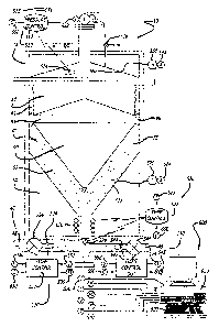
Turning now to the drawings, in which like reference numerals represent like
or
corresponding aspects of the drawings, and with particular reference to FIG.
1, one
embodiment of the intelligent automated material transfer system 110 of the
present
invention includes associating process instrumentation with a refillable
material vessel 120
configured in a vertical format; however, horizontal and other configurations
may be used.
The material vessel includes a main body 150, a top 122, and one or more legs
or
extensions 170. The main body of the material vessel is configured in a
cylindrical format
having a lower portion 152 to be connected to the legs 170 and an upper
portion to be
connected to the top. So as to facilitate removal of the top 122 from the
refillable
container 120, a lifting mechanism 130 may be configured adjacent the main
body 150 of
the material vessel. The refillable material transfer system 110 may be
further configured
with a material inlet and outlet manifold 140 positioned below the main body
150 of the
material vessel 120 and adjacent the bottom portion 152 of the vessel.
As shown in FIG. 1, the intelligent material transfer system 110 includes a
plurality
of sensors and transmitters located on the refillable material vessel 120. For
example, on
the top of the vessel 122, a volume sensor 210 and transmitter 215 are located
between a
temperature sensor 220 with transmitter 225 and a pressure sensor 230 with
transmitter
235. As will be appreciated by those of ordinary skill in the art, many
configurations of
the sensors may be employed in such a transfer system. Likewise, the
transmitters may
include a wireless signal 200, hardwired signal or other connection to a
remote receiver.
Such transmissions may include radio frequency, microwave, infrared, coaxial,
universal
serial buss (USB) or other industry standards, such as, but not limited to,
relay wiring,
twisted pair, Bluetooth and Ethernet.
Various other sensors and transmitters may be included in the intelligent
material
transfer system 110, such as a flow inlet sensor 270 with transmitter 275 and
flow outlet
sensor 280 with transmitter 285 positioned in or about the fluid inlet outlet
manifold 140
and vessel support device (legs or pedestals) 170. Similarly, the vessel 120
may be
connected to a weight sensor 290 and transmitter 295, such as a load cell or
similar device
at or near the bottom 152 of the vessel. Further, identification devices 240
with
transmitters 245, such as a radio frequency identification device (RFID), may
be attached
CA 02626674 2008-04-18
WO 2007/048011 - 8 - PCT/US2006/041193
to or otherwise associated with the vessel. For purposes of locating such a
material vessel,
a global positioning system (GPS) device 250 and transmitter 255 may be
associated with
the automated material transfer system. Additionally, a mechanism for tracking
the time
that fluid has been retained in the vessel, such as a time sensor 260 with
transmitter 265
may be configured with the system. Other timer related events, such as, but
not limited to,
depressurizing, start and end fill times may be monitored and/or tracked.
Further, a sensor
may be associated with the lifting mechanism 130 to indicate when the lid has
been lifted
or removed from the main body of the vessel. Such sensors may be passive or
include the
ability for intelligence, including operator input, local display and other
functions.
Alternatively, the sensors may be very simple devices, such as color dots,
irreversible
moisture indicators, conductivity sensors, pH sensors and the like. Other
instrumentation
may include devices for measurement and/or monitoring of gas properties and/or
material
properties.
Referring now to FIG. 2, some of the instrumentation shown in FIG. 1 has been
adapted for connection to a computer, microprocessor or other data processing
system 300.
For example, the volume or level sensor 210 is associated with a computer
connection 217,
the temperature sensor 220 is associated with a computer connection 227 and
the pressure
sensor 230 is associated with a computer connection 237. Similarly, the RFID
device 240
has a computer connection 247, and the GPS device 250 has a computer
connection 257.
Likewise, inlet and outlet flow sensors 270 and 280 include computer
connections 277 and
287. As described with reference to FIG. 1, any of the sensors (such as system
time and
material weight) shown therein or described regarding instrumentation suitable
for such a
material transfer system may be connected to the data processing system 300.
A data processing system 300 of the automated material transfer system 110 may
take many configurations suitable for retrieving the data from the various
instrumentation,
processing of data to provide alarms, time and date information, event
information, fault
data, financial data, calculation of fluid and other properties associated
with the refillable
material vessel 120. The computer control system typically will include a
processor 310 or
similar computing device, a display device 320 and an operator input device
340. The
computer system may further include a modem 350 or other connection(s) for
integrating
the automated material transfer system to a remote monitoring system, an
intranet, the
Internet or other system. In addition, the automated material transfer system
shown in
CA 02626674 2008-04-18
WO 2007/048011
- 9 - PCT/US2006/041193
FIGS. 1 and 2 may require a separate power source, such as alternating current
(AC) or
direct current (DC), for example, local batteries. It will be appreciated by
those of
ordinary skill in the art that each of the individual instrumentation may have
its own
internal power source, such as a battery, or may be connected to a central or
external
power source.
As shown in FIG. 3, the processor 310 (FIG. 2) may include diagnostic logic,
financial logic, operating logic and wireless logic. The processor may be
associated with
random access memory (RAM), read only memory (ROM) and other data storage
devices.
The data processing system may also comprise a more simpler device, such as a
data
logger with ability to retrieve data stored in such a device with minimal
processing
capabilities. The data processing system may further include an analog-to-
digital (A/D)
and/or digital-to-analog (D/A) interface 360 (FIG. 2), and some
instrumentation may
connect directly to the processor via USB or other communication devices. It
will be
appreciated by those of ordinary skill in the art various configurations of
the instruments,
processors, data logger, memory devices, modems and other devices shown in
FIGS. 1
through 4 may be altered to achieve the complexity or simplicity of a desired
refillable (for
example, intelligent and/or portable) material (thick or otherwise) transfer
and dispensing
system in accordance with the present invention.
Referring now to FIG. 4, various configurations of a microprocessor based
distributed data acquisition system 300 may be implemented in accordance with
the
present invention. For example, the microprocessor 310 may be configured with
a display
device 320, input/output device 340 and printer 370. Various configurations of
the
input/output device, such as a keyboard, keypad, touch screen, personal device
assistant
(PDA) and other electronic and mechanical devices are contemplated by the
present
invention. Likewise, the operator display may be a conventional cathode ray
tube (CRT),
plasma, liquid crystal diode (LCD), light emitting diode (LED) or other known
or yet to be
developed operator interface systems that can provide a graphical, textual or
other display
capability. Likewise, the printer system may be a conventional dot matrix,
laser or thermal
paper apparatus. The data acquisition system may include electronic storage
devices 386,
such as removable diskettes, compact disks (CD), digital video disks (DVD),
laser disks
and other such data storage mediums. The microprocessor may have other storage
capabilities, such as read-only memory (ROM) 382 and random access memory
(RAM)
CA 02626674 2008-04-18
WO 2007/048011 - 10 - PCT/US2006/041193
384. The microprocessor may have serial (for example, USB) and parallel (for
example,
RS-232) interface connections 390 for connecting to intranets, the Internet,
broadband,
cable and other systems. The microprocessor may also be connected to a modem
350 for
wireless, phone line, broadband, cable and other connections.
The microprocessor 310 and other aspects of the present invention may be
configured with external or local alternating current (AC), direct current
(DC) or other
power supplies (not shown). The microprocessor may also interface with an
analog-to-
digital (A/D) and digital-to-analog (D/A) 360 device for interfacing with the
various
volume, pressure, temperature, flow and other sensors and instrumentation 217,
237, 227,
277, 287, 297, 247, 257 as heretofore described. Alternatively, such devices
as the RFID
247 and GPS 257 may connect directly to the microprocessor via a USB or other
interface.
The microprocessor may also be configured to interface directly with
programmable logic
controllers (PLC) 512, 522, 532, 552 for regulating pressure, temperature,
flow and other
process parameters.
Alternatively, the microprocessor may connect with the
programmable logic controllers or other control devices through the AID and
D/A
converter.
One embodiment (prototype) of an intelligent material transfer system 110 of
the
present invention is shown in FIGS. 5, 6 and 7. As shown in FIG. 5, a remote
unit 400
includes a level sensor 410 having an external power supply 412. The level
sensor is
connected to a transmitter 414 for sending the level signal and an
identification signal to a
host unit 420. The host unit includes a data logger 422 operably connected to
a receiving
unit 424 for obtaining the level and identification signals from the remote
site transmitter
414. The host unit further includes a power source 426 that may be configured
for use
with a cigarette lighter or other 12 volt source to allow the host unit to be
mobile (in a car,
truck, etc.). Further, the host unit includes a cell phone 428 or other
broadcast device
connected to the data logger for transmitting data obtained from the remote
unit and
retained in the data logger. The connection between the receiving unit 424 and
the data
logger may be via serial connections (such as USB) or parallel connections
(such as RS-
232).
As shown in FIG. 6, the level sensor and encoder 410 may include a dial and
may
be mounted on the top 122 of the refillable material vessel 120. The level
sensor may be
connected to the remote transmitter 414 via standard electrical wires 415 or
other suitable
CA 02626674 2008-04-18
W02007/048011 11 PCT/US2006/041193
- -
connections. As shown in FIG. 7, the signal from the level encoder may be
connected to a
signal transmitter (LP Gas Stationary Tank Monitor) 417 having a 0-5 volt
signal that is
converted to a 4-20 milliamp signal by a signal conditioner 413 (Omega) that
feeds the RF
transmitter 414. Each of the remote unit and host unit devices may be standard
"off the
shelf' components. Alternatively, custom devices may be configured and
packaged into a
single unit for the remote and host units.
Referring again to FIG. 5, a computer processing system 430 of the present
invention includes a standard personal computer (PC) station 432 connected via
serial
cable 434 to a phone line modem 436. In operation, the automated material
transfer
system 110 was positioned several miles from the local computer system 430.
The remote
unit 400 was activated such that the amount of fluid in the vessel 120 was
detected by the
level sensor 410 and sent via transmitter 414 to a receiver 424 of the host
unit 420, which
were operable in an automobile. Data was periodically sampled and stored in
the data
logger 422, transported, and transmitted via cell phone 428 to the central
processing
system 430. At the local site of the central processing system, the PC 342 was
activated to
initiate the modem 436 to pick up the signal from the host unit 420. The
central
processing system's PC was configured to include software to retrieve the data
signals via
the modem line and process the data for display on the operator interface
associated with
the computer processing system.
As shown in FIGS. 5-7, a prototype of the automated material transfer system
of
the present invention was configured with a personal computer (PC) to acquire
and
manage data from a remote refillable material vessel. The prototype system
acquired and
managed the data with wireless communication links from a refillable material
vessel
positioned at a remote location where there were theoretical barriers to data
acquisition,
including minimal access, minimal power, no wiring, no land lines, no cellular
coverage,
physical (line-of-sight) barriers to long range radiofrequency (RF), and/or
insufficient cost
justification for a satellite link. The prototype mobile data acquisition
system included
components (RF receiver, and data logger with a modem) that received the data
through
wireless systems, stored the data, and transmitted the data through wireless
systems.
The data from a level device configured to work with a refillable material
vessel
was transmitted through a wireless system to a mobile data logger operably
connected to a
modem or other transmission device. In this prototype, the vessel level data
was stored on
CA 02626674 2008-04-18
WO 2007/048011 - 12 - PCT/US2006/041193
the datalogger and transported. The level data was transmitted from the data
logger
through wireless (RF) devices, a cellular phone and land phone lines to a
personal
computer (PC) having a modem. The software on the PC received and managed the
level
data. The data acquisition system was configured to acquire the level of
grease in a
cylinder (vessel) with wireless data transmission, transporting data between
coverage areas
of cellular phone systems with a vehicle, and tracking grease usage over time.
During
testing of the prototype, the cylinder identification and level signal was
successfully
transmitted from a first location via an RF signal through air to a vehicle
outside the first
location, then from the vehicle through a cell phone to a computer at a second
location.
Several transmissions were completed and the data tabulated on the computer.
The RF components outperformed design specifications by transmitting from
inside the top collar of the cylinder, and with metal doors at the first
location closed,
through the concrete wall to the vehicle outside. The transmitted electronic
level signals
were obtained from a 250 gallon horizontal oil tank. As shown in FIGS. 5-7, a
dial/electronic encoder replaced an existing float gauge, and a signal
transmitter ("LP Gas
Stationary Tank Monitor") and signal conditioner ("Omega") sent the signal to
the RF
transmitter (black box). Advantages of reapplying these pre-engineered
"propane"
components include that they simply piggy-back on most float gauges, and are
already
intrinsically safe and UL listed for hazardous environments, which may be
present in an
application where oil is dispensed.
As will be appreciated by those of ordinary skill in the art, the type of data
acquired, level transmitter, wired communication link between the level
transmitter and RF
transmitter, and power sources may be configured with various alternate
devices and
systems. The land line could be removed, without altering the basic scope of
the
invention. The RF transmitter may be configured amongst a range of
frequencies, wherein
50 MHz is low, enabling communication through some physical barriers. In such
a system
the power consumption (less than 50 A between readings) is low.
Referring now to FIGS. 8-10, the intelligent material transfer system 10 of
the
present invention may be configured to automate and control a refillable
material vessel
20. The refillable material vessel and its compressed gas source can be
portable. The
control system may also link and communicate with another automated material
transfer
systems and with other control and information systems. The automated material
transfer
CA 02626674 2008-04-18
WO 2007/048011 - 13 - PCT/US2006/041193
system mcmaes a control device, database, instrumentation, operator interface,
power
source, processor, and receiver/transmitter. The processor includes logic for
diagnostic,
financial, operating, and wireless data. The power source includes portable
sources, such
as battery and photovoltaic (PV), and the receiver/transmitter includes
wireless
communication, such as radio frequency (RF). The data includes information
from a
control system database and another control systems and information systems.
The data
includes, but is not limited to, alarm information, dates and times, events,
faults, financial
data, global position, interface identification, system identification,
material identification,
operator identification, material properties, gas properties, flow rates,
pressure,
temperature, and volume.
The control systems of the present invention allow a refillable material
vessel to be
a fully automated portable system. The control system may be self-powered,
self-
controlled and constantly linked with other control systems and information
systems. The
control system can initiate communication with another control system and/or
information
system, such as those for filling, transporting, inventorying, transferring,
monitoring and
controlling refillable material vessels and other containers. Example
communications
include, "Container #1 OK.", and "Help! I'm LASD Container #1, its noon, 1-27-
05, and
I'm empty, cold, and lost at GM in Warren, MI!".
The high levels of automation and communication of the present invention were
previously unavailable with commercial refillable material transfer system
technology.
The control system and its components are preferably small and light,
including miniature
electronic components, relative to the refillable material transfer system, to
be portable.
The control system components preferably have a low cost and low energy
consumption,
including miniature electronic components, to be practical. Currently
available devices
may perform the various functions of the control system. The high levels of
automation
and communication for the control system of the present invention convert the
refillable
material vessel into a fully automated portable system.
Referring now to FIG. 8, the intelligent material transfer system 10 includes
a
vessel 20 having a force transfer device 90 contained within a fluid space 40
and gas space
80. The vessel further includes a false bottom 50 so as to constrain the
material 42. The
force transfer device further includes a tangential element 95 and stabilizers
96. Fluid may
be transferred into and out of the container via a manifold 45, having inlet
piping 48 and
CA 02626674 2008-04-18
WO 2007/048011 - 14 -
PCT/US2006/041193
outlet piping 46. In accordance with the present invention, various control
systems may be
associated with the automated material transfer system. For example, a
pressure control
system 510 may be associated with the upper portion of the vessel having a
pressure
control device 512, such as a programmable logic controller (PLC), connected
to a
pressure sensor 514 located within or on the vessel. The pressure control
device is
operably connected to a gas (two way) valve 518 configured in the top or lid
of the vessel.
Similarly, a temperature control system 520 may be associated with the lower
portion of the vessel 20. The temperature control system may include a
temperature
controller 522, such as a PLC or other control device, operably connected to a
temperature
sensor 524 located within the fluid manifold 45 or otherwise positioned to
sense an
appropriate portion of the fluids temperature. The temperature controller is
further
operably connected to a heat transfer (heating and/or cooling) coil 526 or
other mechanism
for imparting thermal, kinetic or other energy to the fluid. The temperature
controller may
be connected to one or more temperature sensors located proximate the heating
coil, in the
material inlet conduit 48, the material outlet conduit 46 or any other desired
location
within the material manifold 45. The pressure and temperature control systems
of the
automated material transfer system 10 of the present invention may include
local operator
interfaces, such as displays and keyboard inputs for monitoring the pressure
and
temperature, as well as providing control set points and other data or alarm
points to the
controllers. Likewise, the controllers may include operator alarms, shut off
mechanisms
and other features known to those of ordinary skill in the art.
The intelligent material transfer system 10 of the present invention may
include
other control devices, such as programmable logic controllers and programmable
recording
controllers (PRC) to control various aspects of the material transfer system
regarding
sensors as shown in FIGS. 1 and 2. For example, an inlet flow control system
530 may be
associated with the fluid (material) inlet manifold 48. The inlet flow
controller may
include a control device 532 associated with a flow sensor 534 positioned
within the inlet
piping or other conduit. The flow controller also is operably connected to an
inlet flow
valve 536. Similarly, a flow outlet controller 540 may be associated with the
outlet
manifold 46. The outlet controller may include a flow control unit 542
operably connected
to a flow sensor 544 and flow outlet valve 546 positioned within the outlet
piping or other
conduit. In accordance with the present invention, the flow controllers may
include
CA 02626674 2008-04-18
wo 2007/048011 - 15 -
PCT/US2006/041193
operator input devices or interfaces for connecting to configuration devices.
Likewise, the
flow controllers may include visual displays of the flow sensor information,
as well as
alarms and other data or processed information.
The material transfer vessel 20 may be further configured with a high level
sensor
system 560 and a low level sensor system 570. The level sensor systems may be
configured with sensors or switches 562, 572 and alarm indicators or displays
564, 574.
The high and low level sensors may be operably connected to the flow inlet and
flow
outlet controllers 532, 542 so as to provide high fluid level and low fluid
level shut off
capabilities. For example, during a fill cycle, the inlet flow controller 532
may be
configured to close the inlet flow control valve 536 when the high level
sensor 560 detects
that the force transfer element 90 has come into contact or otherwise
activated the high
level switch 562. At that time or alternatively, the high level sensor may
activate the
visual and/or audible high level alarm 564. Likewise, the outlet flow control
unit 542 may
be configured to close the flow outlet valve 546 when the vessel is in
operation and the
force transfer device 90 contacts or otherwise activates the low level switch
572. The low
level system 570 may be configured to send a signal to the flow outlet
controller and/or
activate the alarm 574. In addition, a volume or level sensor 550 may be
configured with
an output 552 that may be integrated into the flow control systems for feed
forward, feed
back, shut off or other functions to be integrated into the flow controllers.
Referring now to FIG. 9, an automated computer control system 600 may be
associated with the intelligent material transfer system 10. The computer
control system
includes a main computer controller 610, such as a microprocessor or other
device for
processing input data and providing output data. The computer control system
may
include ROM, RAM or other memory storage devices for maintaining data and
processed
information. The control system also includes a user interface 620, which may
provide a
graphical display, keyboard and other mechanisms for operator output and
input. The
system may be further configured with Internet, serial and parallel
connections for
integration into networks and communication with other control devices. For
example, the
pressure controller 512 may include an output 515 that is operably connected
to the
computer controller 610. The connection may be through an analog-to-digital
interface
(not shown), cabling, wiring or other suitable interface device. Similarly,
the temperature
controller 522, flow input controller 532 and flow output controller 542 may
each include
CA 02626674 2008-04-18
WO 2007/048011 - 16 - PCT/US2006/041193
outputs 525, 535, 545 to regulate their respective process apparatus, such as
flow valves.
Each of the controller outputs 515, 525, 535, 545 may be operably connected to
the
computer controller. Similarly, volume sensor 550, high level sensor 560 and
low level
sensor 570 may be connected to the computer controller. The output from the
computer
controller 650 may be connected to the pressure controller, temperature
controller and flow
controllers to provide set points and other control or process information.
As shown in FIG. 3, the computer control system may include a processor with
diagnostic logic, financial logic, operating logic, wireless logic and other
processing
systems for different levels of sophistication of computer control and data
acquisition. The
computer control system may also include a database having alarms, date
information,
events data, fault data, financial data and material properties such as flow
rate,
temperature, pressure volume as well as position information, identification,
material
properties, operator identification and other system and process variables.
The computer
control system will probably require an external power source, but may be self
contained
with battery or other AC/DC power sources. The computer system may also
include a
wireless modem or other device for connection into an intranet or internet
system. The
operator interface may be a graphical user interface or other digital display
device. Analog
controllers, recorders and display devices may be also associated with the
computer
control system of the present invention.
Referring now to FIG. 10, integrated material transfer and dispensing system
110 is
configured with an automated control system 700 having a PLC, PRC, computer
controller
or other computer processing system 710. The material vessel 120 and fluid
outlet
manifold 140 are configured to feed through a pumping system 730 and/or an
applicator
system 740. Inputs to the process control system 710 may be configured as
shown in
FIGS. 8 and 9, and may include, but are not limited to, any instrumentation
shown in
FIGS. 1 and 2. Likewise, any other process control variables required for
control of the
pumping system 730 and/or application system 740 may be included as inputs to
and
outputs from the process controller 710.
The integrated material control system 110 may be further configured with a
fluid
control valve 720 associated with the fluid inlet and outlet manifold 140. The
computer
controller 710 may be associated with the base and pedestal 170 of the vessel
120, or may
be located remotely and operably connected to the instrumentation and control
devices.
CA 02626674 2008-04-18
WO 2007/048011 - 17 - PCT/US2006/041193
Piping or conduits from the outlet of the fluid vessel 120 may be connected to
the pumping
system 730 and/or application system 740 by a variety of mechanisms. For
example, the
pipes or conduits 145 from the fluid vessel may be connected via a manifold
732 or
directly to one or more pumps 734. Instrumentation such as from a pressure
and/or flow
sensor 736 may be fed back to the control system 710. Similarly, the control
system may
be connected to pump motor drive or controller 738 to operate the pumping
mechanisms.
Additional pipes or conduits 147 may provide fluid communication between the
pumping
system 730 and the application system 740. As shown in FIG. 11, the automated
material
transfer system 110, which may be configured as heretofore described regarding
FIG. 10,
may be connected directly to one or more applicators 740 via conduits or pipes
148, 149
without the need for intermediary pumps.
Such integrated material transfer systems may be used for providing oils,
greases,
mastics, sealants, elastomers and other materials such as liquid sound
deadeners. Such
materials may include, but are not limited to, thick fluids, viscous fluids,
semi-solid fluids,
visco-elastic products, pastes, gels and other fluid materials that are not
easy to dispense.
The fluid pumping system may include booster pumps in series or in parallel
for the
manifold. In addition, the applicator may include its own booster pumps or
other drive
mechanisms in addition to the pumping system 730. The applicator system may
further
include metering devices and local control devices that contain
instrumentation that may
be integrated into the computer control system 710 of the present invention.
Referring now to FIGS. 12-16, the automated material transfer system of the
present invention may be configured in a complete assembled package,
hereinafter called a
"station." The automated station may be pre-mounted, pre-piped, pre-wired, pre-
programmed, pre-configured, pre-calibrated, and pre-tested. The interfaces may
be quick
disconnects for the compressed gas, power, and thick fluid; and plug-and-play
controls for
data logging, flow, operation, pressure, and weight. The automated material
transfer
station may automatically deliver thick (high viscosity) fluid or other
material from one or
more refillable material transfer subsystems (for example, FIGS. 14A and 14B).
The
automated material transfer station may automatically receive and store
material from
other material systems, and automatically transfer this material to other
systems, such as
pumping systems and applicator systems. The automated material transfer
station
interfaces with other systems with minimal effort. The station is configured
with one or
CA 02626674 2008-04-18
WO 2007/048011 - 18 - PCT/US2006/041193
more material transfer vessels that may be removed from the station when empty
and
replaced with vessels filled with material, such as LASD.
The general system components (FIG. 15) may include, but not limited to, the
following:
(1) Skid, for supporting the system;
(2) Refillable and/or automated material transfer subsystems;
(3) Piping, for filling, pressurizing, and delivering thick fluid or other
materials
from the material transfer subsystems;
(4) PLC with touch screen, for controlling the system and data logging;
(5) Scales or
sets of load cells, for measuring the material transfer subsystems
and material weights;
(6) Other instrumentation and controls; and
(7) Cabinet, for enclosing the entire system for protection and aesthetics.
The automated material transfer station of the present invention is the first
known
material transfer system to be configured with a cabinet (climate controlled
housing) and
package process controls (FIG. 12). The automated station includes known or
modified
apparatus, such as scales and load cells, sources of compressed gas and/or
power,
automation devices and one or more material transfer subsystems, for example,
automated,
refillable vessels (containers). Several material transfer subsystems, pumping
systems and
applicator systems could be placed in series or parallel with one or more
automated
stations of the present invention so as to increase overall system capacity.
Wireless
interfaces may be added to the automated material transfer station to enable
remote
monitoring and/or control. Such system controls may be configured to automate
the
material delivery from the material transfer subsystems.
For one embodiment of the automated material transfer station (FIGS. 13A,
13B),
the space envelope may be seven (7) feet in length by four (4) wide by seven
(7) feet high;
however, the system is scalable. Such a sized automated station may be
configured with
at least two refillable material transfer subsystems, each subsystem having
about a thirty-
five gallon flooded capacity. Further, the maximum allowable working pressure
may be
150 psig, for operation with nominal 100 psig compressed air. The material
transfer
CA 02626674 2008-04-18
wo 2007/048011 - 19 -
PCT/US2006/041193
subsystems and piping (manifolds, conduits) should meet the applicable codes
for pressure
service.
Referring now to FIG. 16, one or more automated, refillable material transfer
subsystems 110 of the present invention may be housed within a "cabinet" so as
to provide
a comprehensive automated material transfer station 1000. The automated
station may be
configured into a plurality of partitions including a control section 1010 and
a material
transfer section 1020. The automated material transfer station includes a
housing having a
cover 1030 and a floor and or skid-type configuration 1040. The material
transfer station
includes outer walls 1035, and may include one or more doors windows and other
access
ways, as appropriate. The automated transfer station is configured to be "plug
and play,"
and may be moveable about an industrial manufacturing site, storage area,
loaded onto the
back of trucks, trailers or railcars, and otherwise moveable from place-to-
place.
Depending on the size of the containers and internal control component, the
automated
material transfer station may be a few feet tall and wide or configured with
significantly
larger dimensions. Accordingly, the automated station may be configured to be
stationary
within a warehouse, a factory and other working environments, or the automated
station
may be configured to be movable or portable from one desired location to
another.
In the control section 1010 of the automated material transfer station 1000,
it is
contemplated that the control section will be divided into several
compartments 1060,
1070 with shelving or other partitions 1065, 1075. Similarly, the material
transfer section
may be configured with a single compartment 1050, or may be divided into sub-
compartments as appropriate. It is expected that a heating, ventilating and
air conditioning
(HVAC) system will be supplied to the automated material transfer station such
that the
control section may be cooled, heated or otherwise air-conditioned separately
from the
material transfer section. An insulated dividing wall 1080 may be constructed
between the
two sections so as to isolate the two temperature sections. Not shown in FIG.
16 are the
heating, ventilating and air-conditioning ducts, compressors and other
components. Such
devices may be self-contained within the material transfer station or again
"plug and play"
to the HVAC system where the control station is positioned.
Referring to the control section 1010 of the automated material transfer
station
1000, a first compartment 1060 may be configured to house a microprocessor 310
and
multiple programmer logic controllers 512, 522, 532 and 552. These PLCs may be
CA 02626674 2008-04-18
WO 2007/048011 - 20 -
PCT/US2006/041193
electronically or otherwise connected to the microprocessor via a control
conduit 1310 or
other suitable hard-wired or wireless connections. The PLCs may be connected
by
multiple conduits, cabling, wireless connections 1330 to the instrumentation
and other
devices associated with the material transfer subsystems 10, 110, as shown in
FIGS. 1, 2, 8
and 9. The microprocessor may further be configured to connect via a cabling
conduit or
wireless connection 1320 to a cabling tray or other conduit system 1090 so as
to connect
the microprocessor to a display system 320 and input output system 340, a
printing system
370 and modem 350 having connections 1325 to the conduit system.
Further, the microprocessor 310 may be connected to an analog-to-digital (A/D)
.. and/or digital-to-analog system 360. The AID system may be connected to an
outside
conduit 1120 for receipt of signals from material transfer devices in same
station, other
stations or external devices such as pumps, spray devices and robots (see
FIGS. 10, 11 and
18). The automated control station may further include a communication
connection 1110
for connecting to the computer modem, to a phone line, data signals and
wireless signals.
The automated station may further include switches, controls and other
operator interface
devices 1130 located on the outside of the cabinet. The automated station also
includes a
power coupling 1150 for supplying AC and/or DC power. The automated station
may also
include its own power generating station and uninterruptible power supply.
The material transfer section 1020 of the automated material transfer station
1000
.. includes one or more refillable (intelligent, automated) material transfer
subsystems 110
having vessels 120, lid lifting mechanisms 130, main bodies 150, fluid
manifolds 140 and
gas inlets 160. Although not fully described regarding this embodiment, the
other features
of the refillable material transfer systems described herein and incorporated
by reference
are applicable to this embodiment. The automated material transfer station may
include
.. outside couplings for gas inlet and outlet 1210, fluid inlet 1220, fluid
outlet 1230 and other
connections as appropriate. Instrumentation, such as pressure and temperature
sensors,
may be connected directly to the control system section or may be connected to
an outside
coupling 1125. Such a coupling may allow input and output data from other
automated
stations and remote devices within a manufacturing plant or other facility,
for example,
control systems for pumps, spray devices and robotics. Similarly,
instrumentation signals
coming from the material transfer cabinet 1020 through the outside electric
connection
1125 may be connected directly into the input electrical connection 1120 to
the AID device
CA 02626674 2008-04-18
WO 2007/048011 - 21 - PCT/US2006/041193
360, which in turn may connect to the microprocessor 310 and logic controllers
512-552.
Instrumentation and control devices located within the material transfer
section 1020 and
vessel compartment 1050 may be connected directly to the outputs from the
logic
controllers via cabling 1330 or other suitable systems, such as wireless
connections (for
example, radio frequency and microwave signals).
When at least one material transfer subsystem 110 is included in the material
transfer section 1020 of the automated material transfer station 1000, the
material vessels
120 may be configured such that one system is filling as another system is
emptying
(FIGS. 12, 13B, 16). The vessels may be the same size or of different sizes
(FIG. 17). In
addition, compound material transfer subsystems may be configured such that
two or more
vessels of different sizes may be connected in series to obtain efficiencies
as a first larger
vessel (having a force transfer device of a first aspect ratio) feeds one or
more second
smaller vessels that may have force transfer devices with different aspect
ratios than the
larger vessel. The material transfer subsystems may feed pumps and/or directly
feed
material to a device such as a robotic sprayer (applicator) or "shot meter."
Likewise,
multiple vessels may be in fluid communication with one or more material
(fluid)
manifolds that are connected to one or more pumps and applicators. As shown in
FIG. 17,
the automated material transfer system may be externally fed by larger
material transfer
systems, such as those on the back of a railcar or truck. Further, the vessels
may be
positioned side by side or stacked on top of each other for efficiency of
storage within the
compartment 1050 of the material transfer section 1020 of the automated
material transfer
station 1000. Large storage tanks of fluid and other materials may be
configured to feed
several such automated control stations.
The vessel (container) 20, 120, force transfer device 90, and/or other items
in
.. contact with the material may be equipped with a lining (not shown). The
materials of
construction suitable for the lining may include, but are not limited to,
alloys, composites,
elastomers, metals, plastics, polymers, rubbers, wood fiber and other natural
and synthetic
materials. The forms of the lining may include, but are not limited to,
aftached (form-
fitted) and independent (stand-alone); flexible and rigid; and applied and pre-
formed. The
functions of the lining may include:
(1) Protecting the underlying items from corrosion and/or erosion (a
"liner");
CA 02626674 2008-04-18
-22 -
WO 2007/048011
PCT/US2006/041193
(2) Providing a designated "wearing" component that may be replaced,
based on cleaning and/or wear;
(3) Providing a surface in contact with the material that is smoother
than the underlying surface;
(4) Providing a component impregnated with a release agent to improve
material transfer and/or cleaning;
(5) Providing a component impregnated with an antimicrobial material
to decrease microbial growth; and
(6) Providing a designated component for electrical and/or thermal
conductance and/or resistance (resistance heating and/or heat insulation).
Figure 17 provides a summary of the evolution of refillable material transfer
technologies over about a twelve year span. Within that period changes were
made in the
following areas:
= Fluids
= Container size
= Container mobility
= Container internals
= System sophistication
= System configuration
= System functionalities
= System automation and intelligence
For the ten stages (A to J) represented in Figure 17, the following is a brief
representation of the past and anticipated changes.
Referring to FIG. 17A:
Fluids: liquids such as fuels (diesel, gasoline), oils (lubricating,
vegetable)
Container size: small (25 gallon)
Container mobility: fixed and non-portable
Container internals: non-existent
System sophistication: primitive
System configuration: single container for each fluid
System functionalities: storage and transfer fluid to a container or vehicle
System automation and intelligence: none
CA 02626674 2008-04-18
WO 2007/048011 - 23 -
PCT/US2006/041193
Referring to FIG. 17B:
Fluids: new and recyclable liquids such as new and used lubricating oils
Container size: small (25 gallon)
Container mobility: portable
Container internals: non-existent
System sophistication: more sophisticated
System configuration: dual containers one for new fluid one for used fluid
System functionalities: storage, transfer fluid to and from vehicles
System automation and intelligence: none
Referring to FIG. 17C:
Fluids: semi-solids such as lubricating greases
Container size: bulk size (600 gallon)
Container mobility: transportable
Container internals: fairly sophisticated follower device
System sophistication: more sophisticated
System configuration: single large containers transported to user's site
System functionalities: storage and normally transfer to a grease pump
System automation and intelligence: none
Referring to FIG. 17D:
Fluids: semi-solids such as lubricating greases
Container sizes: bulk size (600 gallon) and multiple small (25 gallon)
Container mobility: transportable bulk and stationary or portable small
Container internals: fairly sophisticated follower device
System sophistication: still more sophisticated
System configuration: large containers transported to and from the user's
site to oil refiners and multiple small containers at the user's site
System functionalities: bulk storage and transfer to small containers; small
container storage and transfer to grease pumps
System automation and intelligence: none
Referring to FIG. 17E:
Fluids: semi-solids such as Adhesive Sealants and Mastics (ASM) and/or
liquids
Container sizes: intermediate bulk size (300 gallon)
Container mobility: transportable intermediate bulk
Container internals: more sophisticated follower device for semi-solids
System sophistication: still more sophisticated
CA 02626674 2008-04-18
- 24 -
WO 2007/048011
PCT/US2006/041193
System configuration: large containers transported to and from the user's
site to fluid providers
System functionalities: bulk storage and transfer to ASM pump
System automation and intelligence: none
Referring to FIG. 17F:
Fluids: semi-solids such as Adhesive Sealants and Mastics (ASM) and/or
liquids
Container sizes: intermediate bulk size (300 gallon) and two small (25
gallon)
Container mobility: transportable intermediate bulk and stationary small
Container internals: more sophisticated follower device
System sophistication: still more sophisticated
System configuration: large containers transported to and from the user's
site to fluid providers and multiple two containers at the user's site
System functionalities: intermediate bulk storage and transfer to small
containers;
Small container storage and transfer to ASM pumps
System automation and intelligence: some automation and nominal
intelligence
Referring to FIG. 17G:
Fluids: semi-solids such as Adhesive Sealants and Mastics (ASM) and/or
liquids
Container sizes: intermediate bulk size (300 gallon) and two small (25
gallon)
Container mobility: transportable intermediate bulk and stationary small
Container internals: more sophisticated follower device
System sophistication: still more sophisticated
System configuration: large containers transported to and from the user's
site to fluid providers and multiple two containers at the user's site. Small
containers in
environmentally controlled cabinet
System functionalities: intermediate bulk storage and transfer to small
containers;
Small container storage and transfer to ASM pumps
System automation and intelligence: some automation and nominal
intelligence
Referring to FIG. 17H:
Fluids: semi-solids such as Adhesive Sealants and Mastics (ASM) and/or
liquids
CA 02626674 2008-04-18
WO 2007/048011 - 25 -
PCT/US2006/041193
Container sizes: transportable bulk (600 gallon) bulk and intermediate bulk
size (300 gallon)
Container mobility: transportable bulk and stationary, cleanable
intermediate bulk
Container internals: still more sophisticated follower device
System sophistication: still more sophisticated
System configuration: transportable bulk is trailer to tractor to and from
the user's site to fluid providers and multiple intermediate bulk containers
at the user's
site, in environmentally controlled cabinet
System functionalities: bulk storage and transfer to intermediate bulk
containers;
Intermediate bulk containers storage and transfer to ASM pumps
System automation and intelligence: significant automation and increased
intelligence
Referring to FIG. 171:
Fluids: semi-solids such as Adhesive Sealants and Mastics (ASM) and/or
liquids
Container sizes: transportable bulk (600 gallon) bulk and intermediate bulk
size (300 gallon)
Container mobility: transportable bulk and stationary, cleanable
intermediate bulk
Container internals: still more sophisticated follower device
System sophistication: pumpless, simple and smart
System configuration: transportable bulk is trailer to tractor to and from
the user's site to fluid providers and multiple intermediate bulk containers
at the user's
site, in environmentally controlled cabinet
System functionalities: bulk storage and transfer to intermediate bulk
containers; intermediate bulk containers storage and configured to transfer
ASM directly to
the point of applications
System automation and intelligence: more significant automation and
increased Intelligence
Referring to FIG. 17J: Multiple refillable material transfer systems may be
configured on a cargo truck and cargo trailer. The configuration of these
multiple systems
may be independent configurations (for example, independent systems, and
independent
instrumentation and controls), combined configurations (for example,
integrated systems,
and integrated systems and controls), and various hybrid configurations (for
example,
independent systems, and integrated instrumentation and controls). In one
anticipated
embodiment of a hybrid configuration for bulk transport of a single material
(for example,
automotive LASD (Liquid Applied Sound Deadener)), twenty refillable material
transfer
systems, each system four feet length by four feet width, would be on a cargo
trailer that is
CA 02626674 2008-04-18
wo 2007/048011 - 26 -
PCT/US2006/041193
forty feet length by eight feet width. In this configuration, the compressed
gas piping
would be manifolded together (integrated), the material piping would be
manifolded
together (integrated), and the instrumentation and controls would be
integrated. However,
in this configuration, each of these twenty refillable material transfer
systems would be
operated independently (hybrid). A common material inventory control
methodology,
FIFO (First In First Out), may be accomplished by independently and
sequentially filling
and emptying the refillable material transfer systems. In another anticipated
embodiment
of a hybrid configuration for semi-bulk transport of multiple materials (for
example,
automotive epoxy resin, automotive epoxy hardener, automotive sealant, and
automotive
structural adhesive), four refillable material transfer systems, each system
four feet length
by four feet width, would be on a cargo truck, with a bed sixteen feet length
by eight feet
width. In this configuration, the compressed gas piping would be manifolded
together
(integrated), and the instrumentation and controls would be integrated.
However, in this
configuration, the material piping would be separate. A common material
delivery
methodology, "milk runs", may be accomplished by independently filling and
emptying
the refillable material transfer systems.
As further shown in the drawings for purposes of illustration, the present
invention
also is directed to a pumpless material dispensing system for dispensing
various materials,
including, but not limited to, LASD, oils, greases, mastics, sealants,
elastomers and other
types of fluids. The system includes an automated material transfer system
utilizing a
material containment vessel having an upper region incorporating a motive
force, and a
bottom region with a material ingress and egress opening. A diconical or other
shaped,
level-instrumented force transfer device may be located in the material
containment area.
The present invention further includes incorporating a data acquisition system
into known
and yet to be developed refillable material transfer system technology. The
automated
material transfer system is further configured to interface with a metering
device system
and/or a robotic material dispenser system.
The high levels of automation and communication of the present invention were
previously unavailable with commercial refillable material transfer system
technology.
The control system and its components are preferably small and light,
including miniature
electronic components, relative to the refillable material transfer system, to
be portable.
The control system components preferably have a low cost and low energy
consumption,
CA 02626674 2008-04-18
WO 2007/048011 - 27 -
PCT/US2006/041193
including miniature electronic components, to be practical. Currently
available devices
may perform the various functions of the control system. The high levels of
automation
and communication for the control system of the present invention convert the
refillable
material vessel into a fully automated portable system.
Referring now to FIG. 18, the pumpless material dispensing system 2000 of the
present invention includes an automated material transfer system 110, a
metering device
system 800 and a robotic material dispenser system 900. The automated material
transfer
system 110 is configured with a control system 700 having a PLC, PRC, computer
controller or other computer processing system 710. Inputs to the process
control system
710 may include, but are not limited to, any instrumentation shown in FIGS. 18
and 19.
The automated material control system may be further configured with a fluid
control
valve 720 associated with the fluid inlet and outlet manifold 140. The
computer controller
710 may be associated with the base and pedestal 170 of the vessel 120, or may
be located
remotely and operably connected to the instrumentation and control devices.
The
automated material transfer system may be configured for providing oils,
greases, mastics,
sealants, elastomers and other materials such as liquid sound deadeners. Such
materials
may include, but are not limited to, thick fluids, viscous fluids, semi-solid
fluids, visco-
elastic products, pastes, gels and other fluid materials that are not easy to
dispense. The
computer control system 710 may be configured to interface with the metering
device
system 800 and the robotic material dispenser system 900 the of the present
invention.
The automated material transfer system 110 may be configured with a pressure
sensor 230 that may be connected as an input to the process controller 710.
The process
controller may include an output control signal 1780 for regulating a flow
control valve
780 interposed between the material vessel 120 and a pressurized gas (or other
fluid) input
conduit (pipe, line) 790. The automated material transfer system further
includes an inlet
conduit (pipe, line) 148 and an outlet conduit (pipe, line) 146. The outlet
manifold 140 is
in fluid communication with a material transfer conduit (pipe, line) 145
having
instrumentation, such as a flow sensor 740 and a pressure sensor 745, operably
connected
to the process controller, which regulates the material outlet control valve
720. The
material transfer conduit 145 is in fluid communication with a material
transfer manifold
(conduit, pipe, line) 750 that is in fluid communication with the metering
device system
800.
CA 02626674 2008-04-18
WO 2007/048011 - 28 -
PCT/US2006/041193
The metering device system 800 includes a metering device 810, for example, a
shotmeter, a mastic regulator, or other suitable other flow element, such as a
differential
pressure device (orifice, venturi), a displacement device (gear, piston), a
magnetic device
("mag meter"), an ultrasonic device (Doppler), a mass based device (Coriolis,
MICRO
MOTION), or a device configured for solids (progressive cavity, screw).
Additional
examples of metering devices suitable for use with the pumpless material
dispensing
system 2000 of the present invention are shown in FIGS. 19A-19H. The function
of the
metering device is to provide material 75 (FIG. 20) to the robotic material
dispenser
system 900 through a material transfer conduit (pipe, line) 850. The metering
device
system may further include an input manifold 812, an output manifold 814 and a
material
plunger 816 that are in fluid communication with the material transfer
conduits and
manifolds 145, 750, 850 leading from the automated material transfer system
110 to the
robotic material dispenser system 900.
Referring now to FIGS. 20A and 20B, prior art dispensing systems for thick,
viscous fluids and other such materials include a container or refillable
material transfer
subsystem, a pump, a metering device and an applicator. Such prior art systems
may have
metering devices with significant flow restrictions in their inlet and/or
outlet, and may be
configured with actuation for their dispense stroke only. Such systems require
significant
energy from pumps to transfer material through the metering device inlet
and/or outlet
restrictions to actuate the metering devices during their refill cycles. As
shown in FIG.
20B, the pumpless material dispensing system of the present invention
substantially
eliminates the flow restrictions in the inlet and outlet of the metering
device, and may add
actuation for the refill stroke of the metering device. The system of the
present invention
decreases the energy required to transfer material through the metering device
to the
applicator. The metering device may be further configured with improvements,
including
inlet and outlet components having increased flow capacity and components for
actuation
in the refill stroke. The material dispensing system of the present invention
does not
require a pump, is simpler, has fewer components and requires less space than
prior art
dispensing systems. The system of the present invention includes lower-cost
lower-
pressure components upstream of the metering device, and costs less to
purchase, install,
operate and maintain.
CA 02626674 2008-04-18
WO 2007/048011 - 29 -
PCT/US2006/041193
Referring again to FIG. 18, the robotic material dispenser system 900 includes
a
robot arm 910, an applicator mount 920 disposed at a distal end of the robot
arm and a
material applicator (dispenser) 930 fixed to the mount. The robot arm extends
up from a
base 915, and is movable through a number of axes, allowing it to move to the
desired
position with respect to a part or piece (for example, an automobile door) 960
being coated
or treated and to obtain the proper orientation with respect thereto. In the
embodiment
shown in the FIG. 18, the material applicator 930 is a broad slit nozzle. As
those skilled in
the art will appreciate, any type of dispensing outlet may be used, depending
on the
application parameters and the desired configuration of material 75, 975 being
applied, for
example, spray guns, pin-hole applicators and nozzles, contact and non-
contact, air-
atomizing and airless, such as cone, flat (fan, slit, slot), and stream
(needle, swirl).
A robot controller 1000 controls the position, orientation and speed of
movement
of the robot arm 910 and all of its elements by one ore more control signals
1900 to the
robotic material dispenser system 900. The elements of the robot move with
respect to
each other and the base end 915 of the robot. The robot controller controls
the position
and speed of the robot and material applicator 930. In accordance with the
present
invention, the robot controller also receives input signals and generates
output signals to
operate the metering device system 800. A material transfer conduit (pipe,
line) 950 that is
in fluid communication with the material transfer conduit 850 from the
metering device
system 800 and that is connected to material applicator may include
instrumentation, such
as a flow sensor 940 and a pressure sensor 945, operably connected to the
robot controller.
More specifically, the robot controller 1000 controls the volume of the
material 975
being applied to the part 960 by the material dispenser 930. The robot
controller may
monitor and control the operation of the metering device through a control
signal 1800 to
the metering device system 800, for example, controlling the position of a
piston in a
shotmeter.
The robot controller may be configured to control the charging and
discharging of the material 975 by controlling air valves, pressure
regulators, inlet valves
and outlet valves (not shown). The robot controller is also linked 1700 to the
computer
processing system 710 of the control system 700 and the various
instrumentation of the
automated material transfer system 110 so as to allow feedback and feed
forward control
of the pressure in the material vessel 120 and the flow and pressure of the
material in the
conduits 145, 750, 850 and 950 of the pumpless material dispensing system. An
CA 02626674 2008-04-18
wo 2007/048011 - 30 - PCT/US2006/041193
alternative embodiment of a metering device system 800 and a robotic material
dispenser
system 900 having a double acting shotmeter unit and robotic servo control
unit is shown
in FIG. 21.
As shown in FIGS. 22A-22D, the integrated material transfer system of the
present
invention may include a refillable material vessel 2000 configured in a
vertical format;
however, horizontal and other configurations may be used. Referring to FIG.
22A, the
material vessel includes a main body 2020, a top portion 2030 and a bottom
portion 2010,
which may include a plurality of legs 2070 or extensions and a base 2090. The
base may
be configured for sliding in and out of the automated material transfer
station 1000 (FIG.
16).
As shown in FIG. 22A, the main body of the material vessel 2000 may be
configured in a cylindrical format, wherein the top of the refillable
container is configured
as a two piece portion connected by a series of removable flanges or screw-
type
mechanisms, such as eye nuts on the ends of rods. The refillable material
vessel may be
further configured with a material inlet and outlet manifold positioned below
the main
body 2020 of the vessel and adjacent the bottom portion 2010 of the vessel, as
shown in
FIGS. 22C and 22D and as heretofore described regarding FIGS. 1 through 24.
Likewise,
the refillable material vessel may be further configured with controls and
other
mechanisms as heretofore described regarding FIGS. 1 through 24. The vessel
may be
configured with a lifting mechanism 2700.
Referring to FIG. 22A, the refillable material vessel 2000 may be further
configured with one or more clean-out ports 2100 configured on the lower
portion 2010 of
the body 2020 of the material vessel. The clean-out port may be configured as
any suitable
mechanism as is known to those of ordinary skill in the art, such as a four-
inch flanged two
piece circular-shaped device that is secured to the vessel body. The clean-out
port may
include a first inner portion (piece) bolted to the vessel body and a second
outer portion
(piece) removably bolted or otherwise secured to the first portion of the
clean-out port.
The clean-out port may further be configured with a sample valve 2200.
A separate sample valve 2200 may also be configured on the lower portion 2010
and/or upper portion 2030 of the body 2020 of the material vessel 2000. The
sample valve
may be configured as any suitable mechanism as is known to those of ordinary
skill in the
CA 02626674 2008-04-18
WO 2007/048011 - 31 -
PCT/US2006/041193
art, such as a two piece flange, wherein the first inner portion (piece) is
secured to the body
of the vessel and a second inner portion (piece) may be removably secured to
the first
piece via bolts, nuts or other suitable mechanism. The sample valve may
include a spigot
(port) 2250 having a handle and outlet (opening) for allowing the user to
remove a quantity
of material from the vessel. The spigot outlet may be further threaded or
otherwise
configured for connecting to a hose or other conduit.
The upper portion 2030 of the vessel 2000 may be configured with one or more
site
windows (viewing ports) 2300 for observing material and the internal
components within
the vessel. For example, a first sight window may be used for providing a
light source into
the vessel so that the internals of the vessel may be viewed through a second
window.
Similarly, a camera or other mechanism may be used to record changes in the
material
within the vessel through one of the view ports and may contain its own light
source.
Alternatively, the viewing ports may be configured with a fixed or removable,
still or
video camera system for observing and recording the material and internal
components of
the vessel.
The upper portion 2030 of the refillable material vessel 2000 may further
include a
valve or other entry port 2400 for spraying or otherwise introducing a biocide
or other
agent into the material vessel before or after it is filled with its primary
material, such as
LASD. The biocide valve may be configured as any suitable mechanism as is
known to
those of ordinary skill in the art. The top portion of the vessel may further
include one or
more valves or ports 2500 for introducing and releasing pressurizing air or
inert gas, as
may be required for the fluid or material to be transferred into and out of
the vessel. The
gas valve may include quick disconnects for compressed air, nitrogen or other
pressurized
gas source.
As further shown in FIG. 22A, the refillable material vessel 2000 may include
an
force transfer device (internal follower device, boat) 2040 as heretofore
described
regarding FIGS. 1 through 9. The internal walls of the vessel may be
configured from
welded steel (ASME vessel), and may be further coated with a protective
material, such as
an epoxy paint, an oil, a rust inhibitor or a relatively inert material.
The refillable material vessel 2000 may be configured with specific features
for
application wherein the material to be transferred into and out of the vessel
is a liquid
CA 02626674 2008-04-18
WO 2007/048011 - 32 -
PCT/US2006/041193
applied sound deadener (LASD). Such features include a closed fluid
containment formed
from a basic material of construction of mild steel rated for at least seventy-
five (75) psig,
quick disconnect valves for entry and exit of the LASD, and quick disconnect
valves for
compressed air or other gas. The refillable material vessel may also include a
service
valve with an air chuck, a forklift base near the bottom portion 2010 of the
vessel,
mechanical protections and internal surface coatings. The vessel may include
an internal
follower device (boat) having an annulus device that is variable in diameter,
or may be
configured such that the follower device is adaptable for various annulus
devices to create
different spaces or gaps between the follower device and the internal walls of
the vessel.
The vessel may be further configured with an access port (not shown) for
changing the
annulus on the follower device (boat).
As shown in FIG. 22A, the refillable material vessel 2000 of the present
invention
may further include a data logger 2600 that may be configured with various
features as
heretofore described regarding FIGS. 1 through 24. Additional aspects for the
data logger
may include a microbe detector (for example, a CO2 detector), a particulate
detector and/or
an odor detector, wherein the detectors may include a monitoring device with
audible
and/or visual alarms. The vessel may be associated with a wireless device for
transfer of
information from the data logger via a cell phone, or other such radio
frequency,
microwave, infrared or laser device. The data logger and/or vessel may
interface with a
systems locator, such as a GPS device. The data logger and/or vessel may
further include
a radio frequency identification (RFID) system. The data logger may further
interface
with sensors, monitors and controls for temperature, pressure, humidity and pH
detection
and data storage. The data logger system may further include and interface
with sensors,
monitors and controls for material level and flow, which may be connected to
internal limit
switches. Various alarms may be further configured to interface with the data
logger and
such sensors, monitors and controls.
The refillable material vessel 2000 of the present invention may further be
configured so that one vessel is stackable upon another vessel. An LED or
other light
source may be configured under the top portion 2030 of the vessel for
illuminating the
internal portion of the vessel for viewing through a site window 2300. Other
suitable
materials of construction for the vessel include stainless steel, plastic,
composites and
CA 02626674 2008-04-18
- 33 -
wo 2007/048011
PCT/US2006/041193
aluminum. The follower plate may further be configured for adapting to a wiper
system
for cleaning the inside walls of the vessel.
The refillable material vessel 2000 may be further configured with valves,
conduits
and pipes as shown in FIGS. 1 through 21 so as directly feed a shotmeter,
robot or other
material applicator device. The refillable material vessel of the integrated
material transfer
system of the present invention may be configured for stationary or removable
placement
within a cabinet system as shown in FIGS. 1 through 21.
As shown in FIGS. 23A, 23B, 23C and 24A, 24B, 24C , the integrated material
transfer system of the present invention may include a refillable material
vessel 3000
configured in a vertical format; however, horizontal and other configurations
may be used.
Referring to FIG. 23A, the material vessel includes a main body 3020, a top
portion 3030
and a bottom portion 3010, which may include a plurality of legs or extensions
3070 and a
base 3090. The base may be configured for sliding in and out of the automated
material
transfer station 1000 (FIG. 16). The vessel may be configured from carbon
steel and other
suitable materials of construction for the vessel include stainless steel,
plastic, composites
and aluminum. The vessel internal walls may be coated with a protective
material, such as
an epoxy paint, an oil, a rust inhibitor or a relatively inert material.
As shown in FIG. 23A, the main body 3020 of the refillable material vessel
3000 of
the present invention may be configured in a cylindrical format, wherein the
top of the
refillable container is configured as a two piece portion wherein the top
portion 3030 is
welded or otherwise secured to the main body. The material vessel may further
be
configured so that one vessel is stackable upon another vessel. The refillable
material
vessel may be further configured with a material inlet and outlet manifold
3500 positioned
below the main body of the vessel and adjacent the bottom portion 3010 of the
vessel, as
shown in FIG. 23C and as heretofore described regarding FIGS. 1 through 9.
Likewise,
the refillable material vessel may be further configured with controls and
other
mechanisms as heretofore described regarding FIGS. 1 through 18.
Referring to FIGS. 23A-23C, the refillable material vessel 3000 may be further
configured with one or more clean-out or access ports 3100 configured on the
body 3020
of the material vessel. Each clean-out port may be configured as any suitable
mechanism
or device as is known to those of ordinary skill in the art, such as a four-
inch, two piece
CA 02626674 2008-04-18
WO 2007/048011 - 34 -
PCT/US2006/041193
circular-shaped flange that is secured to the vessel body. As shown in FIG.
23B, a clean-
out port may include a first inner portion (piece) 3120 bolted or otherwise
secured to the
vessel body and a second outer portion (piece) 3110 removably bolted or
otherwise
secured to the first portion of the clean-out port. One or more of the clean-
out ports may
further be configured with a sample valve (FIG. 22A). The access ports are
configured so
that the vessel may be cleaned without having to remove or otherwise
disassemble the
upper portion 3030 from the body of the vessel. High pressure fluid hoses may
be used
through the access ports to wash the inside of the vessel and the force
transfer device 4000.
During the wash procedure, cleaning fluid may exit through the manifold 3500
via the
access pipe 3540 (FIG. 23C). The clean-out ports may be position near the
bottom portion
3010 of the vessel and may also be positioned at higher vertical locations on
the vessel for
access to the inside of the upper portion 3030 of the vessel.
The upper portion 3030 of the vessel 3000 may be configured with one or more
site
windows (viewing ports) 3300 for observing material and the internal
components within
the vessel. For example, a first sight window may be used for providing a
light source into
the vessel so that the internals of the vessel may be viewed through a second
glass or
polycarbonate window. Alternatively, a light source may be introduced through
another
port 3500 configured in the upper portion of the vessel. An LED or other light
source may
be configured under the top portion of the vessel for illuminating the
internal portion of the
vessel. A camera or other mechanism may be used to record changes in the
material
within the vessel through one of the view ports, and may contain its own light
source.
Alternatively, the viewing ports may be configured with a fixed or removable,
still or
video camera system for observing and recording the material and internal
components of
the vessel.
The 3300 sight window may also have the following functions:
= Access for visual inspection of the amount of material in the vessel
(for example, empty or full).
= Access for visual inspection of the physical characteristics of the gas
and material in the vessel (for example, color, defects, foreign material,
indication of
material mixing (for example, striations on the material surface from the
follower device),
CA 02626674 2008-04-18
WO 2007/048011 - 35 - PCT/US2006/041193
opaque/reflective, presence of material surface treatments (for example,
biocide), texture,
uniformity).
= Access for visual inspection of instrumentation for the physical
characteristics of the gas and material in the vessel (for example, litmus
paper; temperature
cards; humidity cards; microbial detection cards; gas detection cards;
available from Cold
Chain Technologies, Holliston, MA, Drager / Draeger (worldwide), Telatemp,
Fullerton,
CA; and Uline, Lake Forest, CA)
= Access for optical instrumentation, for example, position of the
follower device (laser, RF (Radio Frequency)), visual inspection of the
physical
characteristics of the gas and material in the vessel (still pictures, moving
pictures,
computer-based visual comparators (vision systems)).
= Access for visual inspection of the physical characteristics of the
vessel (for example, clean/dirty, evidence of wear).
= Access for treating the surface of the material (for example with IR
(infrared) light for temperature treatment, and UV (Ultraviolet) light for
microbial
treatment).
In addition, the 3300 sight window may be hinged, or the following additional
functions otherwise provided for, for:
= Access for sampling material from the vessel (for example "thief
hatch").
= Access for rigging the follower device inside the vessel (for
example, during cleaning, or during replacing the Replaceable Annular
Management
Device).
= Access for cleaning the vessel (for example, pressure washing).
= Access for
replacing replaceable gas and/or material and gas
instrumentation (for example, litmus paper, temperature cards, humidity cards,
microbial
detection cards, gas detection cards).
CA 02626674 2008-04-18
WO 2007/048011 - 36 - PCT/US2006/041193
Access for treating the surface of the material (for example with
biocide, diluent) or the vessel (for example, with biocide, release agent).
The upper portion 3030 of the refillable material vessel 3000 may further
include a
valve or other entry port 3500 for spraying or otherwise introducing a biocide
or other
agent into the material vessel before or after it is filled with its primary
material, such as
LASD. The biocide valve may be configured as any suitable mechanism as is
known to
those of ordinary skill in the art. The top portion of the vessel may further
include one or
more valves or ports 3410, 3420 for introducing and releasing pressurizing air
or inert gas,
as may be required for the fluid or material to be transferred into and out of
the vessel.
The gas valve may include quick disconnects for compressed air, nitrogen or
other
pressurized gas source.
As shown in FIG. 23C, a fluid manifold 3500 may be positioned below the bottom
portion 3010 of the main body 3020 of the refillable material vessel 3000. The
manifold
includes a material sample valve 3510 having a valve and handle 3515. The
fluid
manifold further includes a material inlet/exit fitting 3520 and a valve and
handle 3525.
The inlet and outlet connections are in fluid communication with a common pipe
or
conduit 3530 that may be connected to the vessel via a flange 3550 that
couples to an
outlet conduit 3540 configured within the bottom portion of the vessel. The
refillable
material vessel may be further configured with valves, conduits and pipes as
shown in
FIGS. 1 through 21 so as directly feed a pump, shotmeter, robot or other
material
applicator device. The refillable material vessel of the integrated material
transfer system
of the present invention may be configured for stationary or removable
placement within a
cabinet system as shown in FIGS. 12 through 16.
As further shown in FIGS. 23A and 24A-24C, the refillable material vessel 3000
may include a "force transfer device" (internal follower device or boat) 4000
as heretofore
described regarding FIGS. 1 through 9. Referring now to FIG. 24A, the force
transfer
device may be configured with an oval shape in cross-section (egg-shaped in
three
dimensions) or other suitable shape (see FIGS. 8, 9 and 14A) for residing
within the vessel
3000 and moving or following fluid from the top portion 3030 of the vessel to
the bottom
portion 3010 of the vessel. The top portion 4020 of the force transfer device
includes an
opening 4050 to allow access to the inside of the force transfer device. The
opening also
allows any pressurized gas to enter the device so as to provide pressure on
the fluid
CA 02626674 2008-04-18
WO 2007/048011 - 37 - PCT/US2006/041193
contained within the vessel below the force transfer device. The opening may
be
configured with a covering device (for example, a rubber sheet) or valving
device (for
example, check valves) to exclude foreign material from the inside of the
force transfer
device.
The bottom portion 4010 of the force transfer device 4000 may include fixed or
removable ballast or a weight device 4100 secured to the bottom portion. Such
a weight
mechanism may further include one or more notches 4120 (for example, four
notches) to
allow drainage of fluid through the body of the force transfer device to a
drainage plug
4200. A lifting ring 4300 may also be secured to the weight 4100 or wall 4060
of the force
transfer device so that it may be lifted up from the bottom of the vessel to
the top portion
of the vessel during cleaning.
The force transfer device 4000 further includes a removable annular management
device 4500 and one or more stabilizing fins 4600 located along the central
perimeter of
the middle portion 4020 of the transfer device. As shown in FIG. 24B, the
replaceable
annular management device may be configured in a plurality of sections 4510,
4520, 4530,
4540 that each section is positioned between each of the stabilizer fins 4600.
As shown in
FIG. 24C, the replaceable annular management device may be semi-circular in
cross-
section. The replaceable annular management device may have an outer diameter
that is
the same, less than or greater than the outer portion 4630 of each stabilizer
fin. Suitable
materials for the replaceable annular management device include natural and
synthetic
rubbers, VITON, silicone, fluorosilicone, neoprene, EPDM, HYPALON, butyl
nitrile
SBR, and other suitable materials. The replaceable device may be solid,
hollow, semi-
hollow or other various configurations. Such devices are available from AAA
Acme
Rubber Co., a division of Fillipone Enterprises, of Tempe, AZ.
The replaceable annular management device 4600 may be secured to the body
4020 of the force transfer device 4000 by a plurality of screws, bolts or
other mechanisms
to allow the removable annular management device to be serviced (for example,
replaced
with one having a different diameter). As shown in FIG. 24A, the service,
entry or access
port (flange) 3200 is positioned such that when the force transfer device 4000
is at the
bottom of the vessel 3010, the replaceable annular management device is
accessible
through the access port 3200 when the outer portion of the flange is removed.
This
configuration allows for changing the replaceable management device such that
the gap
CA 02626674 2013-09-16
- 38 -
3050 (FIG. 23A) between the vessel wall and the force transfer device may be
varied
depending on the material used in the vessel. For example, a very small
diameter annular
management device may be used to create a large gap, such that a significant
amount of
fluid may pass (be retained) between the wall of the vessel and the force
transfer device.
Conversely, the annular management device may be configured such that it
touches the
inside wall of the vessel so as to scrap or otherwise remove retained fluid
from the vessel
wall.
The refillable material vessel 3000 of the present invention may further
include a
data logger that may be configured with various features as heretofore
described regarding
FIGS. 1 through 9. Additional aspects for the data logger may include a
microbe detector
(for example, a CO2 detector), a particulate detector and/or an odor detector,
wherein the
detectors may include a monitoring device with audible and/or visual alarms.
The vessel
may be associated with a wireless device for transfer of information from the
data logger
via a cell phone, or other such radio frequency, microwave, infrared or laser
device. The
data logger and/or vessel may interface with a systems locator, such as a GPS
device. The
data logger and/or vessel may further include a radio frequency identification
(RFID)
system. The data logger may further interface with sensors, monitors and
controls for
temperature, pressure, humidity and pH detection and data storage. The data
logger system
may further include and interface with sensors, monitors and controls for
material level and
flow, which may be connected to internal limit switches. Various alarms may be
further
configured to interface with the data logger and such sensors, monitors and
controls.
While particular forms of the present invention have been illustrated and
described,
it will also be apparent to those skilled in the art that various
modifications can be made.
Accordingly, it is not intended that the invention be limited by the specific
embodiments
disclosed herein. The scope of the claims should not be limited by the
preferred
embodiments set forth in the examples, but should be given the broadest
interpretation
consistent with the description as a whole.