Sélection de la langue

Search

Sommaire du brevet 2626737 

Énoncé de désistement de responsabilité concernant l'information provenant de tiers

Une partie des informations de ce site Web a été fournie par des sources externes. Le gouvernement du Canada n'assume aucune responsabilité concernant la précision, l'actualité ou la fiabilité des informations fournies par les sources externes. Les utilisateurs qui désirent employer cette information devraient consulter directement la source des informations. Le contenu fourni par les sources externes n'est pas assujetti aux exigences sur les langues officielles, la protection des renseignements personnels et l'accessibilité.

Disponibilité de l'Abrégé et des Revendications

L'apparition de différences dans le texte et l'image des Revendications et de l'Abrégé dépend du moment auquel le document est publié. Les textes des Revendications et de l'Abrégé sont affichés :

  • lorsque la demande peut être examinée par le public;
  • lorsque le brevet est émis (délivrance).
(12) Demande de brevet: (11) CA 2626737
(54) Titre français: FREIN A DISQUE CONCU EN PARTICULIER POUR UN VEHICULE UTILITAIRE
(54) Titre anglais: DISK BRAKE, PARTICULARLY FOR A UTILITY VEHICLE
Statut: Réputée abandonnée et au-delà du délai pour le rétablissement - en attente de la réponse à l’avis de communication rejetée
Données bibliographiques
(51) Classification internationale des brevets (CIB):
  • F16D 65/097 (2006.01)
(72) Inventeurs :
  • TRIMPE, ROBERT (Allemagne)
  • RAFFIN, CHRISTIAN (Allemagne)
  • CAMILO-MARTINEZ, JOSE (Allemagne)
(73) Titulaires :
  • KNORR-BREMSE SYSTEME FUER NUTZFAHRZEUGE GMBH
(71) Demandeurs :
  • KNORR-BREMSE SYSTEME FUER NUTZFAHRZEUGE GMBH (Allemagne)
(74) Agent: SMART & BIGGAR LP
(74) Co-agent:
(45) Délivré:
(86) Date de dépôt PCT: 2006-10-11
(87) Mise à la disponibilité du public: 2007-04-19
Licence disponible: S.O.
Cédé au domaine public: S.O.
(25) Langue des documents déposés: Anglais

Traité de coopération en matière de brevets (PCT): Oui
(86) Numéro de la demande PCT: PCT/EP2006/009796
(87) Numéro de publication internationale PCT: EP2006009796
(85) Entrée nationale: 2008-04-21

(30) Données de priorité de la demande:
Numéro de la demande Pays / territoire Date
10 2005 049 057.3 (Allemagne) 2005-10-13

Abrégés

Abrégé français

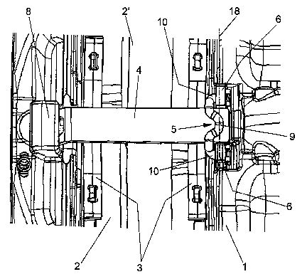
L'invention concerne un frein à disque, conçu en particulier pour un véhicule automobile, comprenant : un étrier de frein (1) qui comporte un espace de réception (15) prévu pour un dispositif d'application de frein, ainsi qu'un disque de freinage (2') pouvant coopérer avec des mâchoires de frein (2), et qui est fixé sur une flasque de frein, et ; un étrier de retenue (4) qui est fixé de manière libérable sur l'étrier de frein (1), et contre lequel reposent des ressorts (3) qui agissent sur l'arête extérieure des mâchoires de frein (2). Selon l'invention, une extrémité de l'étrier de retenue (4) est insérée dans un logement (8) de l'étrier de frein par liaison de forme, tandis que l'autre extrémité est maintenue au moyen d'un élément de fixation (5). Le frein à disque selon l'invention est caractérisé en ce que cet élément de fixation (5) comprend deux branches (10) qui s'étendent à une distance l'une de l'autre, et qui sont insérées et bloquées dans deux orifices (7) adjacents ménagés dans l'étrier de frein, à côté de l'étrier de retenue (4).


Abrégé anglais


Disclosed is a disk brake, particularly for a utility vehicle, comprising a
caliper (1) that is fastened to a brake support and is provided with a
receiving chamber (15) for a clamping mechanism as well as a brake disk (2')
which can be effectively connected to brake shoes (2). The disk brake further
comprises a retaining clip (4) which is removably fastened to the caliper (1)
while supporting springs (3) that act upon the outer edge of the brake shoes
(2). One end of the retaining clip (4) positively lies in a receptacle (8) of
the caliper while the other end thereof is retained by means of a fastening
element (5). The inventive disk brake is configured such that the fastening
element (5) is fitted with two legs (10) which extend at a distance from each
other and are locked in holes (7) located in the caliper (1) on both sides
next to the retaining clip (4).

Revendications

Note : Les revendications sont présentées dans la langue officielle dans laquelle elles ont été soumises.


-9-
Claims
1. A disk brake, in particular for a utility vehicle,
having a brake caliper (1) which has a receptacle space
(15) for a brake application device and which engages
over a brake disk (2') which can be operatively
connected to brake shoes (2), having a retaining clip
(4) which is detachably fastened to the brake caliper
(1) and on which springs (3) which act on the outer
edge of the brake shoes (2) are supported, wherein the
retaining clip (4) bears with one end in a positively
locking fashion in a receptacle (8) of the brake
caliper, and is retained by its other end by means of a
fastening element (5), characterized in that the
fastening element (5) has two limbs (10) which extend
at a distance from one another and which fit in
position in a secured fashion in holes (7) which are
provided on both sides next to the retaining clip (4)
in the brake caliper (1).
2. The disk brake as claimed in claim 1,
characterized in that the fastening element (5) is
embodied as a W-shaped clip.
3. The disk brake as claimed in claim 1 or 2,
characterized in that the limbs (10) extend parallel to
one another.
4. The disk brake as claimed in one of the preceding
claims, characterized in that the limbs (10) extend in
the axial direction of the brake disk (2').
5. The disk brake as claimed in one of the preceding
claims, characterized in that a bearing limb (9) which
bears on the retaining clip (4) is formed between the
limbs (10) of the fastening element (5).

-10-
6. The disk brake as claimed in one of the preceding
claims, characterized in that the limbs (10) are
arranged underneath the bearing limb (9) with respect
to the center axis of the brake disk (2').
7. The disk brake as claimed in one of the preceding
claims, characterized in that each limb (10) is mounted
in a base (6), provided with a hole (7), of the brake
caliper (1).
8. The disk brake as claimed in one of the preceding
claims, characterized in that the limbs (10) penetrate
the bases (6) and are secured at the end by securing
means.
9. The disk brake as claimed in one of the preceding
claims, characterized in that each securing means is
embodied as a standardized part in the form of a splint
(12) or securing sheet-metal element (17).
10. The disk brake as claimed in one of the preceding
claims, characterized in that one of the two limbs (10)
is relatively long and is guided without securing means
in the hole (7) of the assigned base (6).
11. The disk brake as claimed in one of the preceding
claims, characterized in that the bearing limb (9) and
the bases (6) bear on a plane (18) transversely with
respect to the center longitudinal axis of the brake
disk (2').
12. The disk brake as claimed in one of the preceding
claims, characterized in that the fastening element (5)
is retained on that side of the brake caliper (1) which
faces the receptacle space (15).
13. The disk brake as claimed in one of the preceding
claims, characterized in that the bearing limb (9)

-11-
bears against the retaining clip (4) under compressive
stress.

Description

Note : Les descriptions sont présentées dans la langue officielle dans laquelle elles ont été soumises.

CA 02626737 2008-04-21
Disk brake, particularly for a utility vehicle
The invention relates to a disk brake, in particular
for a utility vehicle, corresponding to the preamble of
claim 1.
The retaining clip of such a disk brake, such as is
known for example from DE 8615015 U1, serves mainly as
a counterbearing for springs, in the known disk brake
for leaf springs which stress the brake shoes in a
spring fashion. In this context, the retaining clip is
detachably fastened to the brake caliper so that both
rapid mounting and removal of the brake shoes is
possible. This is in order, for example, to permit easy
access to the brake shoes, which is necessary for
changing the brake lining.
This is also assisted by the fact that the retaining
clip can be attached and removed using simple means,
for which purpose it is, on the one hand, plugged into
a pocket-shaped receptacle of the brake caliper and, on
the other hand permanently connected to the brake
caliper by screwing while spanning a plug-in opening
for the brake shoes.
The pocket-shaped receptacle is provided here on the
side of the brake caliper which forms the outside of
the brake and which lies opposite a brake application
device which is arranged in the brake caliper and which
forms the inside of the brake, that is to say the side
facing the center of the vehicle. In this context, the
receptacle can be formed by mechanical processing or
simply also integrally formed on when the brake caliper
is manufactured by casting.
As mentioned above, the retaining clip is screwed with
its other end, facing the brake application device, to
the brake caliper. However, for this purpose,

CA 02626737 2008-04-21
- 2 -
corresponding costly processing is required, i.e.
boring of the core bore and subsequent cutting of the
thread. Since such disk brakes are manufactured in
large numbers, these operations are not compatible with
optimized fabrication so that the product can overall
only be manufactured at a correspondingly high cost.
It applies equally well to a disk brake in which the
pocket-shaped receptacle is provided on the side of the
brake caliper which forms the inside of the brake. The
retaining clip is secured on the opposite side of the
brake, that is to say what is referred to as the
outside of the brake, by means of a bolt, a disk and
splint, wherein the bolt is connected in a positively
engaging fashion to the brake caliper. This positive
engagement is manufactured above the retaining clip
which is depressed by the splint in conjunction with
the disk and fastened to the bolt.
However, the connection between the bolt/disk and the
splint requires corresponding installation space which,
owing to the prevailing restricted spatial conditions,
can be manufactured only at considerable cost.
Furthermore, the processing of a brake-caliper-end bore
for receiving the bolt is necessary in a direction
other than the main processing direction, which makes
the fabrication overall more difficult. The formation
of the core bore and the cutting of the thread to
manufacture the threaded connection can only be carried
out in a direction other than the main processing
direction so that the same disadvantages apply here.
The invention is based on the object of developing a
disk brake of the generic type in such a way that it
can be manufactured more cost-effectively and simpler
and faster mounting and removal of the brake shoes are
possible.

CA 02626737 2008-04-21
- 3 -
This object is achieved by means of a disk brake having
the features of claim 1.
The invention firstly makes possible, on the one hand,
significantly simpler implementation of the structural
conditions for securing the fastening means since the
required installation space is significantly smaller
than the installation space which is required according
to the prior art, at least in terms of the height of
the installation space which is required.
Particularly given the prevailing restricted spatial
conditions, this fact assumes particular importance
since the mounting and removal of the fastening element
which are necessary to change the brake shoes are
considerably easier.
According to one advantageous development of the
invention, there is provision for the holes in which
the two limbs of the fastening element, which extend at
a distance from one another and preferably parallel to
one another, fit to extend in the longitudinal
direction of the retaining clip. This permits
particularly simple and cost-effective processing of
the holes since the processing direction corresponds to
the main processing direction so that it does not
become necessary to tighten the brake caliper further.
One preferred design of the fastening means is to
embody it as a W-shaped, two-limbed fastening clip
whose center region is supported as a bearing limb on
the retaining clip, while the two limbs extend at a
lower level compared to this bearing limb. The
retaining clip is therefore secured exclusively by the
bearing of the fastening clip which is formed in such a
way that it bears on the retaining clip with a certain
degree of pressure.

CA 02626737 2008-04-21
- 4 -
Particular processing of the retaining clip in the
sense of forming holes or receptacles in order to
receive the fastening means is no longer necessary by
virtue of the invention, which also contributes to
optimizing costs. This applies equally well to the
fabrication of the brake caliper in a casting method
since fewer core parts are now necessary and plug-in
cores can basically be dispensed with.
Since it is now possible to dispense with breakthroughs
in the retaining clip, said retaining clip can not only
be manufactured more easily but it also achieves a
higher degree of stiffness. Furthermore, identical
retaining clips and fastening elements can be used for
differently configured disk brakes, which results in
both a reduction in the warehousing costs and in the
manufacturing costs themselves.
The aforesaid restoring forces which are inherent in
the fastening clip, by means of which the fastening
clip bears under pressure on the retaining clip, mean
that play between the brake shoes and the retaining
clip is reduced so that the sensitivity to shaking
stresses is minimized.
The bearing point of the fastening clip, that is to say
of the bearing limb is preferably located on the
retaining clip in a plane with two bases which have the
holes for receiving the limbs. This avoids the
generation of a bending torque which would additionally
stress the bases. It is therefore possible to
manufacture the bases with a small expenditure of
material.
Further advantageous embodiments of the invention are
characterized in the subclaims.

CA 02626737 2008-04-21
- 5 -
Exemplary embodiments of the invention will be
described below with reference to the appended
drawings, in which:
figure 1 shows a detail of a disk brake according to
the invention in a front view,
figure 2 shows a detail of a disk brake in a plan
view,
figures 3 and 4 each show a detail of the disk brake in
a perspective view,
figure 5 shows a detail of the disk brake, likewise in
a perspective illustration, and
figures 6 and 7 show further exemplary embodiments of a
detail of the disk brake in perspective
views.
Figures 1, 2 and 5 illustrate a disk brake, in
particular for a utility vehicle, having a brake
caliper 1 which has a receptacle space 15 for a brake
application device (not shown), said brake caliper 1
having a brake disk 2' which can be operatively
connected to brake shoes 2 and can be fastened to a
brake carrier.
A retaining clip 4, on which springs 3 in the form of
leaf springs which act on the outer edges of the brake
shoes 2 are supported, is detachably fastened to the
brake caliper 1.
The retaining clip 4 is held in a positively engaging
fashion with one end in a pocket-shaped receptacle 8 on
that side of the brake caliper 1 which lies opposite
the receptacle space 15, while the other end is

CA 02626737 2008-04-21
- 6 -
connected to the brake caliper 1 by means of a
fastening element 5.
This fastening element 5 has, according to the
invention, two limbs 10 which extend at a distance from
one another and which fit in position in a secured
fashion in holes 7 which are provided next to the
retaining clip 4 in the brake caliper 1.
In this context, the fastening element is embodied in
the shape of a W and has, in addition to the two limbs
10 which extend parallel to one another, a central
bearing limb 9 which is supported on the retaining clip
4.
As is shown very clearly by figure 1, the limbs 10
extend underneath the bearing limb 9, with the holes 7
into which the limbs 10 are plugged being located in
bases 6 of the brake caliper 1. These bases 6 are
expediently also integrally formed on when the brake
caliper 1 is cast. Moreover, the holes 7, and therefore
the limbs 10, extend in the axial direction of the
brake disk 2'.
In the exemplary embodiment shown in figure 2, the
limbs 10 of the fastening element 5 are plugged in on
both sides through the bases 6 and each secured at the
end by means of a splint 12 which is guided through a
bore 11 of the assigned limb 10 with a gudgeon 13,
while clamps 14, which adjoin the gudgeon 13 on both
sides, bear on the outside of the limb 10 (figures 3
and 4).
In the exemplary embodiment according to figure 5, a
limb 10 of the fastening element 5 is guided through a
base 6 and is axially secured there by means of a
securing sheet-metal element 17 which is latched in a

CA 02626737 2008-04-21
- 7 -
positively engaging fashion into a groove 16 of the
limb 10.
The other limb 10 is longer and is plugged only into
the assigned base 6, with the one-sided securement of
the other limb 10 by means of the securing sheet-metal
element 17 being sufficient by virtue of the limb 10
being guided over a longer distance.
In figure 2 it is apparent that the bearing limb 9
bears in a plane 18, transversely with respect to the
center axis of the brake disk 2', with the bases 6,
which avoids a bending torque which would stress the
bases 6. The bases 6 can therefore be manufactured
using a small amount of material.
Standard parts can be used as securing elements in the
form of the splint 12 or of the securing sheet-metal
element 17, and the selection in this context is not
restricted to these two embodiment variants. Instead,
other known securing elements can easily also be used.

CA 02626737 2008-04-21
- 8 -
List of reference numerals
1 Brake caliper
2 Brake shoe
3 Spring
4 Retaining clip
5 Fastening element
6 Base
7 Hole
8 Receptacle
9 Bearing limb
10 Limb
11 Bore
12 Splint
13 Gudgeon
14 Clamp
15 Receptacle space
16 Groove
17 Securing sheet-metal element
18 Plane

Dessin représentatif
Une figure unique qui représente un dessin illustrant l'invention.
États administratifs

2024-08-01 : Dans le cadre de la transition vers les Brevets de nouvelle génération (BNG), la base de données sur les brevets canadiens (BDBC) contient désormais un Historique d'événement plus détaillé, qui reproduit le Journal des événements de notre nouvelle solution interne.

Veuillez noter que les événements débutant par « Inactive : » se réfèrent à des événements qui ne sont plus utilisés dans notre nouvelle solution interne.

Pour une meilleure compréhension de l'état de la demande ou brevet qui figure sur cette page, la rubrique Mise en garde , et les descriptions de Brevet , Historique d'événement , Taxes périodiques et Historique des paiements devraient être consultées.

Historique d'événement

Description Date
Modification reçue - modification volontaire 2011-02-17
Demande non rétablie avant l'échéance 2009-10-13
Le délai pour l'annulation est expiré 2009-10-13
Réputée abandonnée - omission de répondre à un avis sur les taxes pour le maintien en état 2008-10-14
Inactive : Page couverture publiée 2008-07-31
Inactive : Notice - Entrée phase nat. - Pas de RE 2008-07-29
Inactive : CIB en 1re position 2008-05-10
Demande reçue - PCT 2008-05-09
Exigences pour l'entrée dans la phase nationale - jugée conforme 2008-04-21
Demande publiée (accessible au public) 2007-04-19

Historique d'abandonnement

Date d'abandonnement Raison Date de rétablissement
2008-10-14

Historique des taxes

Type de taxes Anniversaire Échéance Date payée
Rétablissement (phase nationale) 2008-04-21
Taxe nationale de base - générale 2008-04-21
Titulaires au dossier

Les titulaires actuels et antérieures au dossier sont affichés en ordre alphabétique.

Titulaires actuels au dossier
KNORR-BREMSE SYSTEME FUER NUTZFAHRZEUGE GMBH
Titulaires antérieures au dossier
CHRISTIAN RAFFIN
JOSE CAMILO-MARTINEZ
ROBERT TRIMPE
Les propriétaires antérieurs qui ne figurent pas dans la liste des « Propriétaires au dossier » apparaîtront dans d'autres documents au dossier.
Documents

Pour visionner les fichiers sélectionnés, entrer le code reCAPTCHA :


Pour visualiser une image, cliquer sur un lien dans la colonne description du document (Temporairement non-disponible). Pour télécharger l'image (les images), cliquer l'une ou plusieurs cases à cocher dans la première colonne et ensuite cliquer sur le bouton "Télécharger sélection en format PDF (archive Zip)" ou le bouton "Télécharger sélection (en un fichier PDF fusionné)".

Liste des documents de brevet publiés et non publiés sur la BDBC .

Si vous avez des difficultés à accéder au contenu, veuillez communiquer avec le Centre de services à la clientèle au 1-866-997-1936, ou envoyer un courriel au Centre de service à la clientèle de l'OPIC.

({010=Tous les documents, 020=Au moment du dépôt, 030=Au moment de la mise à la disponibilité du public, 040=À la délivrance, 050=Examen, 060=Correspondance reçue, 070=Divers, 080=Correspondance envoyée, 090=Paiement})


Description du
Document 
Date
(aaaa-mm-jj) 
Nombre de pages   Taille de l'image (Ko) 
Description 2008-04-20 8 274
Dessin représentatif 2008-04-20 1 21
Dessins 2008-04-20 3 85
Abrégé 2008-04-20 1 21
Revendications 2008-04-20 3 78
Rappel de taxe de maintien due 2008-07-28 1 114
Avis d'entree dans la phase nationale 2008-07-28 1 195
Courtoisie - Lettre d'abandon (taxe de maintien en état) 2008-12-08 1 174
PCT 2008-04-20 5 186