Note : Les descriptions sont présentées dans la langue officielle dans laquelle elles ont été soumises.
CA 02628840 2011-04-21
Apr 21, 201111:34 AM PDT 4169201350 To: 18199532476 Page 10/16 From: Perry +
Currier Inc.
ENTERTAINMENT SYSTEM MOUNTABLE IN A VEHICLE SEAT
1. Technical Field:
The present invention relates to an entertainment system, and more
particularly to an
entertainment system capable of being mounted in a seat (e.g. headrest) of a
vehicle.
2. Discussion of the Related Art:
As society becomes more mobile and therefore spends a greater amount of time
traveling
and away from home, demand rises for electronic appliances and devices outside
the home
environment. For example, video screens have been mounted in the headrests of
vehicles,
facilitating video entertainment on the road. These video screens are
connected to video players,
located; for example, in the glove box of the vehicle.
1
PAGE 10118* RCVD AT 41211201111:39:12 AM (Eastern Daylight Time] *
SVR:F0000316 * DNIS:3906 * CSID:4169201350 * DURATION (mm-ss):03-19
CA 02628840 2008-05-07
WO 2007/056345 PCT/US2006/043300
However, the video player and video screen cannot be removed from the vehicle.
Thus, videos may only be viewed with such systems when occupying the vehicle.
In addition,
there is also a risk.of theft of the video screen and video player and
corresponding damage to
the vehicle when the vehicle is unattended. Further, a video screen and player
that is not
removable is difficult to replace or service.
Therefore, a need exists for a video system which is easily removable from a
headrest.
SUMMARY OF THE INVENTION
In accordance with an embodiment of the present invention, an entertainment
system
for a seat of a vehicle is provided. The entertainment system includes a
housing adapted for
being mounted within a seat of a vehicle and a media unit housed within the
housing and
pivotably coupled to the housing. The housing includes a groove formed within
a sidewall of
the housing adapted to engage a movable latch of the media unit.
In accordance with an embodiment of the present invention, an entertainment
system
mounted in a headrest of a seat of a vehicle is provided. The entertainment
system includes a
media unit housing mounted within the headrest. The housing having a first
sidewall, second
sidewall, third sidewall and fourth sidewall and a face. The first and second
sidewalls being
connected to each other via the third and fourth sidewalls, and the first,
second, third and
fourth sidewalls each being substantially perpendicular to the face, and
wherein the housing
includes a pair of first flexible members provided on the second sidewall of
the housing. In
addition, the entertainment system includes
a media unit housed within the housing and pivotably coupled to the housing,
wherein the
first flexible members snap over a pair of tabs located on a surface of the
media unit to hold
the media unit in nlace within the housing.
-2-
CA 02628840 2008-05-07
WO 2007/056345 PCT/US2006/043300
In accordance with an embodiment of the present invention, a support structure
for
supporting an entertainment system within a seat of a vehicle is provided. The
support
structure includes a housing adapted for being mounted within the seat of a
vehicle and for
pivotably housing a media unit therein. Moreover, the housing includes first
biased members
disposed within a face of the housing to provide a force on the media unit in
a direction away
from the housing.
In accordance with an embodiment of the present invention, an electrical
connection
assembly for electrically connecting a media unit housed within a seat of a
vehicle to wire
leads running through the seat of the vehicle is provided. The electrical
connection assembly
includes an electrical connector having first and second opposing pin
connectors, a first
mating pin connector positioned in the seat of the vehicle, and a second
mating pin connector
positioned in the media unit. The first opposing pin connector connects to the
first mating pin
connector and the .second opposing pin connector connects to the second mating
pin
connector.
In accordance with an embodiment of the present invention, an entertainment
system
for a seat of a vehicle is provided. The entertainment system includes a
housing adapted for
being mounted within a seat of a vehicle and a media unit housed within the
housing and
pivotably coupled to the housing. The housing includes at least one of a
groove formed
within a sidewall of the housing adapted to engage a movable latch of the
media unit, a first
flexible member provided on a sidewall of the housing to engage a portion of
the media unit
for snapping the. media unit into place within the housing, or a second
flexible member
disposed in a- face of the housing to provide a spring force on the media unit
in a direction
away from the housing.
-3-
CA 02628840 2008-05-07
WO 2007/056345 PCT/US2006/043300
BRIEF DESCRIPTION OF THE DRAWINGS
Embodiments of the present invention will be described below in more detail,
with reference
to the accompanying drawings:
Figure 1A shows a front view of an entertainment system including a media unit
coupled to a housing mounted in a headrest, according to an embodiment of the
present
invention;
Figures 1B and 1 D show top views of the entertainment system of Figure 1 A
with the
media unit pivoted outward with respect to the housing, according to an
embodiment of the
present invention;
Figures I C and 1 E show front views of the entertainment system of Figure 1 A
with
the media unit pivoted outward with respect to the housing, according to an
embodiment of
the present invention;
Figures 1 F-1 H show sides views of the entertainment system of Figure 1A with
the
media unit pivoted outward with respect to the housing, according to an
embodiment of the
present invention;
Figures 2A and 2B show front views of the entertainment system including the
media
unit coupled to the housing, according to an embodiment of the present
invention;
Figure 2C shows a front view of the entertainment system with the media unit
pivoted
outward with,respect to the housing, according to an embodiment of the present
invention;
Figure 2D shows a rear view of the entertainment system including the media
unit
coupled to the housing, according to an embodiment of the present invention;
Figure 2E shows' a top view of the entertainment system including the media
unit
coupled to the housing, according to an embodiment of the present invention;
Figure 2F shows a bottom view of the entertainment system including the media
unit
coupled to the housing, according to an embodiment of the present invention;
-4-
CA 02628840 2008-05-07
WO 2007/056345 PCT/US2006/043300
Figure 2G shows a side view of the entertainment system including the media
unit
coupled to the housing, according to an embodiment of the present invention;
Figure 2H shows a side view of the entertainment system including the -media
unit
coupled to the housing, with the media unit pivoted outward with respect to
the housing,
according to an embodiment of the present invention;
Figure 3A shows a close-up view of a tab engaged with a slot for restricting
pivoting
of the media unit-with respect to the housing, according to an embodiment of
the present
invention;
Figure 3B shows a close-up view of the tab of Figure 3A in the extended
position,
according to an embodiment of the present invention;
Figure .3C.shows- a close-up view of the tab of Figure 3A in the retracted
position,
according to an embodiment of the present invention;
Figure 4A shows a front view of a headrest including a wired connection,
according to
an. embodiment of the present invention;
Figure 4B shows a close-up view of the wired connection shown in Figure 4A,
according to an embodiment of the present invention;
Figure 5A shows a front view of the entertainment system including the media
unit
coupled to the housing, with a trim portion removed from the housing,
according to an
embodiment of the present invention;
Figure 5B shows a front view of the trim portion referred to in the
description of
Figure 5A, according to an embodiment of the present invention;
Figure 5C shows a close-up front view of a hinge portion coupling the media
unit to
the housing, according to an embodiment of the present invention;
Figure 5D shows a close-up side view of a hinge portion coupling the media
unit to
the housing, according to an embodiment of the present invention;
-5-
CA 02628840 2008-05-07
WO 2007/056345 PCT/US2006/043300
Figure 5E shows a close-up front view of recesses for receiving fixing devices
for
fixing the hinge portion of Figures 5C-5D to the housing, according to an
embodiment of the
present invention;
Figure 5F shows a close-up front view of another hinge portion coupling the
media
unit to the housing, according to an embodiment of the present invention;
Figure 5G shows a side view of the housing including a recess for receiving
the hinge
portion of Figure 5F, according to an embodiment of the present invention;
Figure 6A shows a front view of the housing, according to an embodiment of the
present invention;
Figure 6B *shows a rear view of the housing, according to an embodiment of the
present invention;
Figure 6C shows a bottom view of the housing, according to an embodiment of
the
present invention;
Figure 6D shows a close-up front view of part of the housing, according to an
embodiment of the present invention;
Figure 6E shows a close-up rear view of part of the trim portion, according to
an
embodiment of the present invention;
Figures 7A-7B show an electrical connector running from the media unit,
according to
an embodiment of the present invention;
Figure 7C shows a connector positioned in the media unit for receiving the
electrical
connector shown in Figure 7D, according to an embodiment of the present
invention;
Figure 7D shows an electrical connector, according to an embodiment of the
present
invention; and
Figures 7E-7F show a cover for holding the electrical connector shown in
Figure 7D
in place on the media unit, according to an embodiment of the present
invention.
-6-
CA 02628840 2008-05-07
WO 2007/056345 PCT/US2006/043300
'DETAILED DESCRIPTION OF THE EMBODIMENTS
Disclosed is an entertainment system capable of being mounted in a seat of a
vehicle.
For example, the entertainment system includes a housing mounted in a headrest
of a seat of a
vehicle, such as, for example, an automobile, minivan or sport utility vehicle
(SUV). The
housing may also be mounted in a body of a vehicle seat. The entertainment
system further
includes a media unit that is pivotably coupled to the housing.
Referring to Figures 1 A-1 H and 2A-2H, a headrest 10 includes an
entertainment
system 100 mounted therein. The entertainment system 100 includes a housing
110 and a
media unit 120, which is coupled to the housing 110. Moreover, the media unit
120 includes
a display 130,having a screen for displaying video. The screen is preferably
an LCD type
display, but may be another type of display, such as, for example, an organic
LED or electro-
luminescent display.
In one embodiment, an LCD simultaneously displays different content in right
and left
viewing directions by directionally controlling the viewing angle of the LCD.
In other words,
one passenger can see a program from a first media source from a right side of
the display,
while another can see a program from a second media source from the left side
of the display.
The simultaneous display of different content on the display (e.g., display
130), is
accomplished by superimposing a parallax barrier on a thin film transistor
(TFT) LCD to
enable light from a backlight to separate into right and left directions.
In the present exemplary embodiment, video is supplied from a media source,
for
example, a DVD player 140 provided behind the display 130. The media source
may also be,
for example, a CD-ROM player, a video game player, a videocassette player, a
television
tuner, a radio tuner, a wireless receiver, an MP3 player, a digital video
recorder (DVR), a
device for playing media supplied from a portable storage device (e.g., a
portable hard drive,
memory cards, flash memory sticks, key drives, thumb drives) and/or a device
for playing
-7-
CA 02628840 2008-05-07
WO 2007/056345 PCT/US2006/043300
media supplied from a portable media player, such as for example, an audio or
video ipod .
The media unit 120 may include a memory device, for example, a DVR, which
receives and
stores video programming, and hardware for playing such programming.
Alternatively, the
display 130 can be electrically connected to an auxiliary media source through
auxiliary port
142.
In another alternative, the display 130 is electrically connected to a media
source, for
example, another DVD player in another headrest, via a wired connection
running from the
media unit 120. Referring to Figures 2B, 2D, 2F and 7A-7D, the wired
connection running
from the media unit 120 preferably includes a two-headed electrical connector
150, including,
for example, pin connectors 151 and 152. The pin connector 151 connects to a
mating pin
connector 153 positioned in the headrest 10 (see Figs. 4A-4B), which is, in
turn, connected to
wire leads running through the headrest support rods 15 to connect to a wire
harness or a
distribution box (not shown). By unplugging the pin connectors 151, 153 from
each other, a
user is able to remove the media unit 120 from the headrest 10 without cutting
or pulling
is apart the wires. The pin connector 152 connects to a mating pin connector
154 positioned in
the media unit 120.
Referring to Figures 7A-7F, the electrical connector 150 is positioned at a
rear portion
of the media unit 120, with pin connector 152 connected to pin connector 154.
Connector
150 is held in place by cover 155, which includes a hole 156 for receiving a
fixing device,
such as, for example, a screw 157, and tabs 158 for fitting into slots 159 on
the media unit
120. Referring to*Figures 2D, 5E and 6A-6C, the housing 110 includes opening
169 through
which wires (e.g., connector 150) can be fed.
The wired connection preferably carries, for example, power, ground, and
audio/video
inputs and outputs. For example, video from DVD player 140 may be supplied via
the wired
connection, including electrical connector 150 and connectors 151-154, to a
display located in
-8-
CA 02628840 2008-05-07
WO 2007/056345 PCT/US2006/043300
another headrest of the vehicle. The wired connection may also carry control
signals for a
wireless FM modulator for supplying wireless audio to a vehicle sound system
or to wireless
headphones.
Referring to Figures 1A, 2A, 2B and 5A, the front face of the media unit 120
includes
a plurality of control buttons, for example, a power button 141, a screen mode
button 143 for
controlling aspect ratio, play and stop buttons 145 for controlling play of a
video program and
a source button 147 for controlling the source of a program (e.g., DVD or
auxiliary input).
Depending on the selected sources for each media unit, multiple displays in
multiple
headrests may simultaneously play the same or different programs. The media
unit 120 also
includes an infrared transmitter and receiver 146 for. transmitting, for
example, wireless audio
signals to wireless headphones, and for receiving remote control signals. A
headphone jack
148 is also positioned on the front face of the media unit 120.
The media unit 120 includes slits 168 formed in the body thereof,
creating.openings to
facilitate ventilation and the passage of sound from, for example, a speaker
(not shown)
provided in the body of the media unit 120.
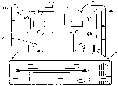
Referring to Figures 2C, 2D, 6A, 6B and 6D, the housing 110 includes a
plurality of
recesses 160 for receiving fixing devices, such as screws 161 for mounting the
housing 110 to
a rigid portion of the headrest 10 (see Fig. 4A). Referring to Figures 2C, 2E
and 6A-6B, the
housing 110 also includes a plurality of flexible members 162, which flex
upward by pressure
from tabs 163 (see Fig. 1D) when the media unit 120 is pivoted into the
housing 110. Once
the tabs 163 pass the flexible members 162, the flexible members flex back
downward to
hold the media unit 120 in place. When the media unit 120 is pivoted out of
the housing (see,
e. R., Figs. 1 B-1 C); the members 162 flex back upward similar to when the
media unit 120 is
pivoted into the housing 110 to allow the media unit 120 to freely rotate. The
above-
mentioned engagement between the flexible members 162 and the tabs 163 allows
for the
-9-
CA 02628840 2008-05-07
WO 2007/056345 PCT/US2006/043300
media unit 120 to be readily snapped into and/or removed from the housing 110
of the
entertainment system without the use of any fasteners, such as, for example,
screws, bolts,
nails, tools, or the like. Thus, the exemplary embodiments of the present
invention allow for
the media unit 120 to be installed and/or removed with very little effort,
which in turn saves
on installation time and avoids having to return the whole headrest but rather
only the media
unit 120 itself, if the media unit 120 needs to be repaired.
As shown in Figures 1A, 1B, 2A, 2B, 2E and 5A, the media unit 120 includes a
tab
167 that can be gripped by a user to pull the media unit 120 out from a
secured position in the
housing 1101 The tab 167 is positioned at a top center portion of the front
face of the media
unit 120.
Referring to Figures 1 C, 1 E, 2C, 2D, 6A, 6B and 6D, the housing 110 includes
flexible members 172 provided within for example, a front face of the housing,
which flex
toward the vehicle seat when the media unit 120 is pivoted into the housing
110 and held in
place by the flexible members 162. When the media unit 120 is pivoted out of
the housing
(see, e.g., Figs. 1B-1C), the members 172 flex away from the seat to provide a
spring force on
the media unit 120 to facilitate rotation of the media unit 120 away from the
housing 110.
Referring to Figures 5A, 5B, 6A and 6E, the housing 110 includes a trim
portion 175,
which is removed from and coupled to the housing by manipulating snap-fit
mechanisms.
For example, the trim,portion 175 includes tabs 176 and 177, which snap-fit
into recesses 178
and 179, respectively. The trim portion 175 and the media unit 120 may be
provided' in
different colors to fit with various interior color schemes of a vehicle.
Referring to Figure 5A, when the trim portion 175 is removed, a user/installer
is able
to access a part of the housing 110 to which a hinge portion 180 is coupled.
As shown in
Figures 5C-5E, the hinge portion 180 includes a plate 181, through which
fixing devices, such
as, for example, screws 182, are driven into recesses 183 formed in the
housing 110.
-10-
CA 02628840 2008-05-07
WO 2007/056345 PCT/US2006/043300
Referring to Figures 5F-5G, a second hinge portion 184, formed on a side of
the media unit
120 opposite to the side on which the hinge portion 180 is formed, fits into a
recess 185
formed in the housing 110. - As a result, the media unit 120 is coupled to the
housing 110 via
hinge portions 180 and 184.
As shown in Figures 1B-1H, 2C and 2H, the media unit 120 can be pivoted
outward
with respect to the housing 110 to adjust a viewing angle of the display 130
and to provide
access to a media source 140 to insert or remove a media storage medium, such
as, for
example, a DVD. The media storage medium insertion point 149 and control
buttons 144 for
the media source 140, such as, for example, an "eject" button, can be located
on a top side of
the media unit 120.
The hinge arrangement permits rotation of the media unit with respect to the
housing
in the range of approximately 0 to approximately 135 . Alternative hinges
known to those
of ordinary skill in the art may be used and the angle range of rotation may
be varied to be
greater or smaller depending on design preferences.
Referring to Figures 3A-3C (see also Figs. 1D, IE, 2D, 2H and 7A-7C), the
media
unit 120 includes a tab 190 on a back side thereof that can be extended to
engage a curved
slot/groove 191 formed in a sidewall of the housing 110. The groove 191
follows the rotation
of the media unit 120 with respect to the housing 110 and, as shown in Figures
2G-2H,
engagement of the tab 190 with the groove 191 restricts an angle of rotation
of media unit 120
in a range of approximately 0 to approximately 45 .
As shown in Figures 3B-3C, the tab 190 can be extended or retracted by sliding
a
handle 192 attached to the tab 190 in opposite lateral directions. When the
tab 190 is in the
retracted position as shown in Figure 3C, the tab 190 is not engaged with the
groove 191. As
a result, the media unit 120 can be pivoted to angles greater than about 45 ,
to, for example,
about 90 and about 135 with respect to the housing 110, as shown in Figures
1C-lE and
-11-
CA 02628840 2008-05-07
WO 2007/056345 PCT/US2006/043300
1 G. As shown in Figure 1 E, pivoting the media unit 120 to greater angles
with respect to the
housing 110 permits access to fixing devices 161 for coupling the housing 110.
to the headrest
10, and to electrical connectors 151 and 153 to facilitate removal of the
housing and/or media
unit from the seat.
s In an embodiment, the media unit 120 can be operated when the media unit 120
is not
positioned in the housing 110. The media unit 120 may receive power by
connecting to a
specialized battery or battery pack, household batteries and/or an AC/DC
adapter. The
connection between the battery pack and the media unit 120 may be provided
through any
appropriate electrical contracts, for example, contacts for connecting to
Lithium or NiCad
batteries. The media unit 120 can connect to an AC/DC adapter via an AC/DC
adapter port.
Alternatively, a battery housing in the media unit 120 can be used to receive
household
batteries or compact battery packs.
Having described the exemplary embodiments of the present invention, it is
further
noted that it is readily apparent to those of reasonable skill in the art that
various
modifications may be made without departing from the spirit and scope of the
invention
which is defined by the metes and bounds of the appended claims.
-12-