Note : Les descriptions sont présentées dans la langue officielle dans laquelle elles ont été soumises.
CA 02633113 2008-06-20
ELECTRIC BASEBOARD HEATER CONTROL
This application claims priority based on U.S. Patent
Application No. 11/852,036 entitled "ELECTRIC BASEBOARD
HEATER CONTROL" filed September 7, 2007, which is herein
incorporated by reference.
FIELD OF THE INVENTION
This invention relates to the art of electric heating systems,
baseboard heaters, thermostats, and electric radiant heating.
BACKGROUND OF THE INVENTION
Electric heaters often make noises as the thermostat controlling a
heater cycles the heater on and off. This noise occurs because of the
expansion and contraction of the components of the heater, in particular the
enclosure for the heater, the heating coil and the brackets for holding the
heating coil. The noise can be quite annoying and disruptive, for example
when the heater is in a room where a person is trying to sleep. The
expansion and contraction of the heater and objects near the heater can
cause wear to the heater itself and to nearby objects. The expansion and
contraction can be especially rapid and more likely to cause noise when the
heater is mounted on an exterior wall of a building and the outside air is
cold.
1
CA 02633113 2008-06-20
OBJECTS OF THE INVENTION
It is a primary object of this invention to provide a system to reduce
the mechanical noise as typically made by electric heaters due to rapid
expansion and contraction of the components of an electric heater as the
heater is turned on and off.
It is a further broad object to provide an electric heater that produces
a steady and therefore more comfortable source of heat.
It is another broad object of the invention to minimize the generation
of radio frequency electrical noise due to switching on and off the heating
elements or controlling the amount of electrical power applied to the
heating elements of an electric heater.
BRIEF SUMMARY OF THE INVENTION
Briefly, these and other objects of the invention are achieved in a
preferred embodiment of the present invention which carries out the
method and apparatus of the present invention. According to the teachings
of the present invention, the preferred embodiment incorporates
enhancements over the state of the art to a thermostat controlling the
electric heater. The enhancements incorporate apparatus or method for
controlling the electric heater such that the power applied to the electric
heater is adjusted continuously to provide just the required heat from the
heater, rather than cycling the heater fully on and off over periods of time
2
CA 02633113 2008-06-20
long enough to cause expansion and contraction of the various parts of the
heater which in turn would potentially induce mechanical noise. That is,
the power is controlled in a manner which keeps the temperature of the
heating elements fairly constant rather than changing rapidly, which
minimizes the gradients of temperature and resultant contraction and
expansion of components of the electric heater.
DESCRIPTION OF THE DRAWING
The subject matter of the invention is particularly pointed out and
distinctly claimed in the concluding portion of the specification. The
invention, however, both as to organization and method of operation, may
better be understood by reference to the following description taken in
conjunction with the subjoined claims and the accompanying drawing of
which:
FIG. 1 is a diagram showing an electric heater powered from house
power passing through a triac circuit controlled by a thermostat;
FIG. 2 shows waveforms for house power gated by a triac circuit
applied to an electric heater such as to achieve production of approximately
50 percent of maximum possible heat;
FIG. 3 shows waveforms for house power gated by a triac circuit
applied to an electric heater such as to achieve production of approximately
33.3 percent (one-third) of maximum possible heat;
3
CA 02633113 2008-06-20
FIG. 4 shows a waveform exemplary of house power with zero
crossing points marked for illustration purposes;
= FIG. 5 illustrates exemplary patterns for the gate input to a power
gating triac type device which would result in application of several
illustrative levels of average power; and
FIG. 6 further illustrates more complex exemplary patterns for the
gate input to a power gating triac type device for producing selected levels
of average power.
DESCRIPTION OF THE PREFERRED EMBODIMENT(S)
It is common in the prior art for an electric heater to be controlled
utilizing an apparatus or method in which a thermostat controls the
application of house power to heating elements of the electric heater and
the thermostat causes switching of the heating elements on or off depending
on the need for heat. There is typically some hysteresis in the switching
such that the house power is applied for on and off periods of at least
several seconds, typically at least 15 seconds or more.
According to the present invention the preferred embodiment teaches
enhancement to the thermostat and control mechanism for an electric
heater. The enhancements provide for the heating coils to have an average
power applied to them which is smoothed over a short period of time while
meeting the overall requirements for heating. The power to the coils is
4
CA 02633113 2008-06-20
smoothed such that as heating requirements vary, the need is met with slow
changes in the average power applied to the heating coils of the heater and
as a result the temperature of the heating elements also varies slowly. This
reduces the degree of overall expansion and contraction of the heating
elements when compared to common methods of the prior art.
Smoothing of the power and reduction of expansion and contraction
of the heating elements and the enclosure of the heater itself potentially
results in a reduction in noise from the heater in comparison to controls of
the prior art. The smoothing of the power and the resultant heat from the
heater also significantly reduces the sharpness of the temperature change
applied by the heater to nearby objects which reduces damage to those
objects due to expansion and contraction caused by sharp heat gradients.
The preferred embodiment of the present invention further teaches
that the smoothing of power applied to the heating elements of the electric
heater can be accomplished by controlling the distribution of power to the
heating elements with a triac or other semiconductor device with similar
function that can switch the alternating current (a.c.) power to the heating
elements fully on or fully off under control of a gate connection. The
preferred embodiment teaches that switching of power applied to the
elements from on to off or off to on is controlled such that the switching
occurs at or near the zero crossing of the alternating current (a.c.) house
5
CA 02633113 2008-06-20
power supply to the heater. This a.c. supply current is typically supplied by
a 110 to 120 volt, or 220 to 240 volt, 50 Hertz or 60 Hertz connection to the
house or building's main electrical power distribution system. Switching
the power to the heating elements at or near the zero crossing of the supply
power reduces radio frequency noise generated by the switching.
The preferred embodiment of the present invention further teaches
that the smoothing of power applied to the heating elements be achieved by
switching the power on and off at a significantly higher frequency than
typically utilized in the state of the art.
In the prior art, a typical minimum time for cycling from on to off or
off to on is typically in the range of five to fifteen or more seconds. For
exemplary purposes the following discussion will describe the prior art
using an exemplary number of 15 seconds for the period of switching.
This means that when a need for more heat is sensed by a thermostat,
full power is applied to the heating elements for at least 15 seconds before
the resultant rise in temperature of the air near the thermostat is close
enough to the desired temperature and the power to the heater elements is
switched off. At the beginning of the "on" period when the heating
elements have just been turned on, the temperature of the heating elements
rises quickly. Once the desired temperature is reached, the heating
elements are turned off and quickly cool. The room then begins to cool.
6
CA 02633113 2008-06-20
When the thermostat senses that the room has cooled below a chosen set
point (a set temperature) the power to the heating elements is again turned
fully on. The repeated switching from application of full power followed
by application of zero power for periods of at least several seconds results
in mechanical expansion and contraction of the heater elements, the heater
enclosure, and objects near to the heater. This mechanical expansion and
contraction creates potential for generation of mechanical noise due to the
shifting or movement of the components of the heater or any nearby
objects.
The preferred embodiment of the present invention further teaches
that the power to the heater is better controlled for purposes of the
invention by providing for switching on or off the heating elements at the
beginning or end of specific cycles of the a.c. (alternating current) supply
power.
The preferred embodiment of the present invention further teaches
that the overall effective power applied over a longer period of time be
adjusted by controlling the number of on and off cycles of supply power
applied to the heating elements. It is further taught that the switching from
on to off or off to on be done at a high enough frequency such that the
number of on cycles and off cycles are distributed evenly over time. For
example, it would be preferable that if 50% power were desired, to achieve
7
CA 02633113 2008-06-20
this by switching power on for one cycle and off for one cycle and to repeat
that, rather than switching power on for five seconds, and off for five
seconds and repeating that. The higher frequency of control switching
(reduced period of control switching) reduces the sharp temperature
gradients in the heating elements.
It is noted that achieving the very highest frequencies of switching,
that is for example one cycle on and one cycle off for 50% power, is not
necessary to achieve the desired smoothing of the power. It would be
acceptable for example to repeat a pattern of two cycles on followed by two
cycles off, or ten cycles on followed by ten cycles off. But at some point a
longer time period for switching on to off or off to on will begin to cause
expansion and contraction of the heating elements which is of enough
significance to potentially produce mechanical noise. Determination of a
precise period for a pattern at which generation of unwanted mechanical
noise would be a possibility would depend upon the specific heater design,
the placement of the heater in a room and other factors such as outside
temperature and amount of air circulation. But a precise choice is not
necessary because switching based upon a reasonably small number of
cycles of house power which is typically 50 or 60 Hertz easily reduces the
switching period below the period of time that would cause mechanical
noise from the heater.
8
CA 02633113 2008-06-20
In the preferred embodiment of the invention the switching is done
with the shortest period of switching, that being a single full cycle of the
a.c. house supply power. At 50 Hertz this would be 1/50th of a second, and
at 60 Hertz the minimum switching cycle would be 1/60th of a second. The
pattern chosen for application of the desired percentage of power should be
the shortest pattern that will produce the percentage of maximum (full)
power that is desired.
Percentage of Power
In conjunction with the method or apparatus briefly herein just
described for smoothly applying a percentage of power to the heating
elements of an electric heater, it is necessary to determine what percentage
of power should be applied in order to meet the heating requirements of the
room. In one example solution from the preferred embodiment the
percentage of power required can be calculated by looking at the
percentage of power now being applied and increasing it by some small
percentage whenever the temperature falls below the set point, or by
decreasing it by some small percentage whenever the temperature rises
above the set point.
As an example, one hundred and one possible settings from 0 percent
(no power) to 100% power (full power) might be provided, and the
apparatus or method for determining the percentage of power could
9
CA 02633113 2008-06-20
increase or decrease the current percentage being applied by one percent
every few seconds. This simple algorithm would mean that once an almost
constant temperature is reached in the room, the percentage of power
applied would be sampled every few seconds and would go up one
percentage or down one percentage every few seconds. Once a state of
fairly constant temperature is achieved, the method and apparatus might
change the sample time of the thermostat to once every 30 seconds or so to
further smooth the power and to account for the delay between when a
change in power to the heating elements actually results in a change in
temperature at the thermostat. With a thermostat on the opposite wall of
the room from a heater, the delay from applying power to being able to
notice the effect of the power at the thermostat could be many seconds or
even minutes. Adaptive algorithms dependent on the precise characteristics
of the heater or room or other similar factors are easily devised by someone
knowledgeable in the state of the art.
Overall Descriptions of Alternative Embodiments
Alternative embodiments of the present invention will now be
described in greater detail to further illustrate the invention.
In a typical heating system a thermostat is used to provide a signal
when there is a need for heat. With a simple typical thermostat there is a
simple signal signifying one of only two possible conditions, the need for
CA 02633113 2008-06-20
heat or the need for no heat. The thermostat determines this by comparing
the temperature of the air surrounding the thermostat with a temperature
pre-set by the user of the heating system. With most typical thermostats of
the prior art there is some hysteresis that keeps the signal for heat on or
off
for some number of seconds or even minutes before the signal changes
from on to off or off to on. Typical thermostats also have some small range
of temperature change that is required before a switch from on to off or off
to on is effected, a typical range of temperature being one-half to three
degrees Fahrenheit.
Power Control Considerations
According to the teachings of the present invention the preferred
embodiment(s) includes an apparatus or method for controlling the
electrical power applied to an electric heater. Further included in the
preferred embodiment of the present invention is apparatus or method of
controlling the power applied for short intervals such that the heater can be
turned fully on or fully off for short periods of time, with that period of
time in the preferred embodiment being based upon a number of full cycles
of house or main power voltage.
The present invention then teaches that by making adjustable the
short intervals of time that the heater is fully on or fully off allows an
adjustable portion of maximum heat to be effected. For example, if for a
11
CA 02633113 2008-06-20
short period of time full power was applied to the heater, and then for a
second short interval of the same time no power was applied, the effective
overall power applied over a longer time period would be 50 percent of
maximum power. As a second example, if full power was applied for one
tenth of a second and no power was applied for three-tenths of a second and
this cycle was continuously repeated, then the average effective power
applied over a long time period could be calculated as:
0.1 seconds /( 0.1 seconds + 0.3 seconds) => .25 => 25%.
Included as a further enhancement to the present invention is the
stipulation that the intervals of time for switching the heater fully on or
fully off be based upon some number of cycles of the main a.c. (alternating
current) electrical power supply, which might typically be 50 or 60 cycles
per second. This provides for the intervals of time to be a specific number
of alternating current cycles.
The present invention further teaches that the switching of power to
the heating elements from on to off, or off to on, be scheduled or timed
such that the switching occurs when the voltage applied to the heating
elements is at or near to the zero voltage crossing of the alternating current
supply. This greatly reduces the radio frequency noise generated by the
switching compared to the noise which might be generated if a switch were
to clamp the output voltage to zero when the input was not near to zero
12
CA 02633113 2008-06-20
volts, or allow the output voltage to be unclamped and jump rapidly from
zero to some higher voltage, and also reduces the power dissipation in the
switching circuitry itself. The switching of the power should also be done
such that only full or complete cycles of the voltage or current waveform
are passed through the switch, in order to avoid inducing direct current
components on the wiring of the circuit or the house power.
The preferred embodiment of the invention further teaches that the
switching of power from fully on to fully off and fully off to fully on occur
frequently enough to provide for slow changes in effective overall power to
the heating elements, with the purpose of minimizing mechanical noise
from expansion and contraction due to sharp gradients or rapid changes in
temperature of the heating element(s). The overall goal is to apply just
enough average power to the heating elements of the heater to keep the
room at the desired temperature, and to slowly vary the power to the
elements to meet the need for heat in the room as determined by the
thermostat. An exemplary period chosen for the preferred embodiment is a
period of ten cycles of the alternating current. This would be one-fifth of a
second at 50 Hertz, or one-sixth of a second at 60 Hertz. The proportion of
power applied would thus be adjustable five or six times per second.
Depending on the mechanical characteristics of the heater, having a period
of time significantly longer than a few seconds could begin to induce
13
CA 02633113 2008-06-20
significant expansion and contraction inducing the possibility of resultant
mechanical noise.
It is noted as further teaching of the present invention that choosing a
short interval between turning power to the heating elements fully on or
fully off does not limit the precision to which the effective power can be
adjusted by proportioning the on and off times. That is, selecting a supply
power alternating current cycle count of ten, for example, does not limit the
number of levels of effective heat that can be applied to only ten. For
example, if 75% power were required, this could be achieved by repeating
two patterns of power application, the first applies power for seven cycles
on and three cycles off, the second applies power for eight cycles on and
two cycles off, so the average effective power after these two patterns
would be ( 7/10 + 8/10 ) / 2=> 0.75 => 75%.
It is a further teaching of the present invention that utilizing repeating
patterns of full power on to full power off allows an increase in the
precision to which average heat can be adjusted. Achieving integral
percentages from one to one hundred percent could be achieved, for
example, by distributing on and off times as evenly as possible across one
hundred cycles of the supply power. Distributing the on and off times
evenly distributes the power applied as evenly as possible across the chosen
period of time.
14
CA 02633113 2008-06-20
DETAILED DESCRIPTION OF THE PREFERRED EMBODIMENT
The preferred embodiment will now be described in greater detail with
reference to the figures of the drawing.
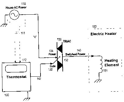
FIG. 1 illustrates a basic electric heater 150 powered from a main
house a.c. power supply 110 with power to the electric heater controlled by
a triac circuit 130. The triac circuit 130 acts as a switch or gate that
allows
power from the house a.c. power source to be applied or not applied to the
electric heater. The house a.c. power 110 is connected through wiring 141
to the power input 131 of the triac circuit. A triac gating signal 142
connected to the gate input 132 of the triac circuitry selectively allows the
house power to flow through the triac to the switched power output 133 of
the triac circuitry. This switched power output 133 is connected through
wiring 143 to heating elements 151 of the electric heater. The triac gate
signal 132 thus controls the application of house power to the heating
element(s) of the electric heater. As shown, a thermostat 100 with
associated processing circuitry produces the triac gating signal 142 which is
operatively connected to the triac circuitry's gate input 132 as the triac
gating signal. The thermostat's processing circuitry can thus control the
application of house power to the heating element(s) of the electric heater.
In another aspect of the preferred embodiment, the thermostat is also
connected to the house power supply 110 through a transformer 111 with
CA 02633113 2008-06-20
this connection 112 optionally supplying power to the thermostat and as
later described and discussed in reference to FIG. 4 providing an a.c. signal
representative of the house power a.c. waveform for the processing
circuitry to anticipate the time of zero-crossing for the voltage or current
of
the house power a.c. waveform.
FIG. 2 is an illustration showing exemplary waveforms of house
power 210, a gating waveform 242 and resultant switched power waveform
243 when a production of 50% of maximum possible power, or resultant
heat, is desired as determined by the processing circuitry of the thermostat.
The house power waveform shown is a typical 240 volt a.c. power source.
The house power waveform as shown is approximately sinusoidal with a
typical frequency of 50 or 60 Hertz. The voltage waveform periodically
crosses the zero axis at points as indicated by tic marks on the diagram of
the house power waveform 210.
Six cycles Cl 201, C2 202, C3 203, C4 204, C5 205, and C6 206 of
the house power waveform are shown as denoted on the time line 245
below the house power waveform. In the preferred embodiment, a triac
gate waveform 242 is applied by the thermostat processing circuitry to the
gate input of the triac circuitry which switches the power through the triac
ON and OFF, by clamping the output voltage to zero when the gate signal
to the triac is OFF. These ON and OFF periods are marked with the gate
16
CA 02633113 2008-06-20
being ON during cycles Cl, C3 and C5 and OFF during cycles C2, C4, C6.
The resultant switched power waveform 243 shows that the voltage output
from the triac circuitry to the heating element(s) has one-half of the output
cycles switched OFF, that is held at zero voltage, and thus one-half of the
power is applied to the heating elements compared to what could be applied
with no switching or gating of the source power.
In the diagram for the switched power waveform, the switched power
is shown as a thick solid black line 260, and the power waveform that
would have existed without gating is shown as a light dashed line 261. If
this exemplary gate waveform is continued over a longer period, one-half
of the maximum full power output from the heater will result. The
temperature of the heating element(s) will remain almost constant because
the gate signal goes on and off at a relatively high frequency compared to
the response time of the heating element(s). This results in a steady output
of heat from the heating elements with no significant expansion and
contraction of the heating elements or the heater enclosure.
FIG. 3 is similar to FIG. 2 except instead of applying one-half of
maximum power as described for FIG, 2, the exemplary gating waveform
342 shown in FIG. 3 produces a switched power waveform 343 with only
one-third of the cycles ON and two-thirds OFF which thus applies one-third
17
CA 02633113 2008-06-20
or 33.3% of maximum power to the heating element(s) of the electric heater
resulting in one-third of the maximum possible heat.
FIG. 4 shows a waveform exemplary of house power with zero
crossing points marked for illustration purposes with diagonal tic marks
401 402 403 and 404 crossing the waveform. As in the other figures of the
drawing cycles Cl, C2 and C3 201 202 and 203 respectively refer to the
first three cycles of the house a.c. power waveform. The first zero crossing
point 401 is near the beginning of cycle C 1, the second 402 is at the end of
C 1 and the beginning of C2 and continuing in the same manner for cycle
C3 and beyond. The zero crossing points are important points to be
recognized by the processing circuitry of the thermostat and utilized to
determine the precise time for turning the gate waveform to the triac
circuitry ON or OFF. The gating signal from the thermostat should be
aligned such that the switch of the triac from ON to OFF or OFF to ON is
achieved as close as possible to the time at which there is zero voltage and
as a result zero current passing through the triac device. The thermostat
would, in the preferred embodiment, use the power leads from a
transformer supplying power to the thermostat from the house power to
observe the house power waveform and anticipate the zero crossing.
These techniques of switching at the zero crossing are well known in
the state of the art with the purpose of switching at the zero crossing point
18
CA 02633113 2008-06-20
being to eliminate both heat dissipation inside the triac device and also to
minimize radiated electro-magnetic noise. It is further noted in the
preferred embodiment that the gating of the house a.c. power be such that
only full cycles of power are switched off by the triac device. More
specifically the control should maintain an equal number of positive and
negative going halves of the power waveform in order to eliminate any
direct current d.c. components from the wires carrying the power. In
another embodiment of the present invention the zero crossing detection
and gate control circuitry may be a part of the triac switching circuitry. The
actual circuitry for control of the gate signal including determining the
detection of the precise zero-crossing point and the timing of the gate
switching into the triac or similar device may be incorporated as part of
either the triac circuitry or in the thermostat or in circuitry separate from
these circuits. The detailed design of the circuitry or method for achieving
switching by the triac circuitry near or at the zero-crossing point is a
detail
of design that can be determined by someone knowledgeable in the state of
the art.
FIG. 5 is a table of exemplary patterns for the gate input to a power
gating triac type device which illustrate an aspect of the preferred
embodiment and would result in application of several illustrative levels of
average power to the heating elements of the electric heater. In FIG. 5,
19
CA 02633113 2008-06-20
column one 501 of the table gives the desired percentage of power. The
second column 502 contains an illustrative pattern for the gate input to the
triac device that, when repeated indefinitely, would result in the desired
level of power. The third and fourth columns 503 and 504 are the number
of ON and OFF cycles respectively of the pattern in the second column
502. The fifth column 505 shows the ratio of cycles ON divided by the
total number of ON plus OFF cycles, which ratio being the fraction of
maximum possible cycles, which is the same as the ratio of power to
maximum power at the output of the triac device. In the first row of the
table 551, a power percentage of 50% of maximum is determined by the
processing circuitry of the thermostat. An exemplary pattern of one cycle
OFF and one cycle ON, repeated indefinitely, results in a ratio of 1/2 the
maximum power passing through the triac device, that is, the number
shown in row 1 column 5 of table 551. It is noted that one cycle OFF and
one cycle ON is the shortest repeatable pattern that would provide 1/2
power, and therefore is the highest frequency pattern that could be applied
for this level of power. Other longer patterns may also be used which
provide the same level of power, that is 50 percent. The second row 552
illustrates a pattern of two cycles OFF followed by two cycles ON which
achieves 50 percent power, with this pattern being of length four cycles. A
third exemplary pattern providing 50 percent power is provided in the third
CA 02633113 2008-06-20
row 553 of the table which is six cycles long, three cycles OFF followed by
three cycles ON, and repeated. The precise pattern chosen during design or
programming of the processing circuitry of the thermostat would be the
choice of the designer and may be dependent on other parameters. For
purposes of minimizing expansion and contraction and minimizing
temperature gradients in the heating elements, the shortest possible pattern
as shown in the first row would typically be chosen. The fourth and fifth
rows 554 and 555 respectively of the table in FIG. 5 further illustrate
patterns for 33.3 percent and 66.6 percent power, that is, applying 1/3 or
2/3 of maximum power.
FIG. 6 further illustrates more complex exemplary patterns for the
gate input to a power gating triac type device for producing selected levels
of average power. As in FIG. 5 the columns are labeled for percent power
applied 601, the triac gate pattern 602, the number of gate ON cycles 602,
the number of gate OFF cycles 604, and the ratio of gate ON divided by
total cycles 605. In this FIG. 6 a constant length pattern twenty (20) cycles
in length is illustrated as shown in the second column 602. Power levels
from 0% up to 100% are shown in the twenty rows of the table with power
levels incrementing by five percent as one goes down the table. It is noted
that a period of one cycle would be 1/60 of a second with 60 Hertz power
21
CA 02633113 2008-06-20
as typical in the United States, and 1/50 of a second in countries with 50
Hertz power.
It is further noted that within the twenty cycles of each pattern the
ones and zeroes indicating ON and OFF cycles are spread relatively evenly
across the twenty cycle pattern. This is not a requirement for achieving
relatively small gradients of temperature in the coils of the electric heater
elements with a period of 20 cycles, which is one-third of a second at 60
Hertz, but the more even the distribution of ON and OFF periods, the
smaller the gradients of temperature will result.
As a further embodiment of the present invention, a heater which is
controlled by an apparatus of the present invention as described in the prior
paragraphs to reduce temperature gradients in the heating elements, the
heater itself can be designed in anticipation of experiencing smaller
temperature gradients. This would allow the heater to possibly be built of
lighter weight materials, simpler design, lower cost of manufacture, or
other such advantages in comparison with competing products.
It will be appreciated that the present invention is not in any limited
by the packaging of the devices. In addition, circuitry of the thermostat, the
triac device, the thermostat processing circuitry or other elements disclosed
in connection with describing the invention may be changed without
affecting the novel aspects of the invention. For example, the thermostat
22
CA 02633113 2008-06-20
can be a simple temperature sensing device with the processing circuitry of
the thermostat contained either within the thermostat or external to the
thermostat. The triac may be contained in a package with processing
circuitry of its own or in conjunction with the processing circuitry of the
thermostat, or all elements of the invention could be combined and
packaged as a unit.
Thus, while the principles of the invention have now been made clear
in an illustrative embodiment, there will be immediately obvious to those
skilled in the art many modifications of structure, arrangements, the
elements, circuitry, materials, and components, used in the practice of the
invention which are particularly adapted for specific environments and
operating requirements without departing from those principles.
23