Sélection de la langue

Search

Sommaire du brevet 2640014 

Énoncé de désistement de responsabilité concernant l'information provenant de tiers

Une partie des informations de ce site Web a été fournie par des sources externes. Le gouvernement du Canada n'assume aucune responsabilité concernant la précision, l'actualité ou la fiabilité des informations fournies par les sources externes. Les utilisateurs qui désirent employer cette information devraient consulter directement la source des informations. Le contenu fourni par les sources externes n'est pas assujetti aux exigences sur les langues officielles, la protection des renseignements personnels et l'accessibilité.

Disponibilité de l'Abrégé et des Revendications

L'apparition de différences dans le texte et l'image des Revendications et de l'Abrégé dépend du moment auquel le document est publié. Les textes des Revendications et de l'Abrégé sont affichés :

  • lorsque la demande peut être examinée par le public;
  • lorsque le brevet est émis (délivrance).
(12) Demande de brevet: (11) CA 2640014
(54) Titre français: ECROU DE SERRAGE
(54) Titre anglais: LOCK NUT
Statut: Réputée abandonnée et au-delà du délai pour le rétablissement - en attente de la réponse à l’avis de communication rejetée
Données bibliographiques
Abrégés

Abrégé français

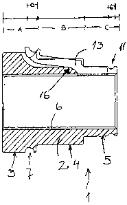
La présente invention concerne un écrou de serrage qui comprend un corps décrou (2), dans lequel se trouve un trou équipé d'un filet intérieur pour un corps de vis pourvu d'un filet extérieur. Dans l'écrou se trouvent des découpes essentiellement axiales (12), qui s'étendent jusqu'au trou sur une partie de sa longueur, et des griffes de verrouillage (13) dans lesdites découpes conçues pour mordre lorsqu'elles sont comprimées contre la vis, afin d'empêcher l'écrou de s'ouvrir.


Abrégé anglais


Lock nut, comprising a nut body (2), in which there is a drill hole equipped
with an internal thread for a bolt body equipped with an external thread. In
the nut there are essentially axial cuts (12), which extend to the drill hole
over part of its length, and locking claws (13) in the said cuts, to bite when
pressed against the bolt, to prevent the nut from opening.

Revendications

Note : Les revendications sont présentées dans la langue officielle dans laquelle elles ont été soumises.


Claims
1. Lock nut, comprising a nut body (2), in which there is a drill hole
equipped
with an internal thread for a bolt body equipped with an external thread, in
which
nut there is at least one essentially axial cut (12), which extends to the
drill hole
over part of its length, and a locking claw (13) in the said cut, to bite when
pressed against the bolt, to prevent the nut from opening, characterized in
that
the cut (12) is of such a shape that a fulcrum (16) is created for the locking
claw
(13), with the aid of which the locking claw can be levered away from the
bolt.
2. Lock nut according to claim 1, characterized in that the cuts (12) are in a
direction that deviates slightly from the radial.
3. Lock nut according to claim 1, characterized in that the locking claws are
elongated and equipped, in the area of the cuts (12) that extends to the drill
hole, with a threaded part (14) corresponding essentially to the internal
thread of
the nut.
4. Lock nut according to any of the above claims, characterized in that the
protrusion of the locking claws (13) in the area of the part (14) is such that
a
tightening device, such as a spring ring (9) brought to the said part (14) of
the
lock nut (1), will press the claw onto the bolt.
5. Lock nut according to claim 1, characterized in that the part of the arm
away
from the bolt part of the fulcrum of the locking claw (13) is raised from the
surface, which is shaped to receive a torque tool.
6. Lock nut according to claim 2, characterized in that if desired the
direction of
the cuts is at a slant, in such a way that the edge, resisting the rotation of
the
nut, of the locking claw (13) set in the cut, is the first to come in contact
with the
surface of the bolt.
7. Lock nut according to any of the above claims, characterized in that there

6
are at least two, and usually at least three cuts (12) and locking claws (13)
corresponding to them.
8. Lock nut according to any of the above claims, characterized in that the
part
(4) of the nut (1) for a torque tool is a hexagon and that there are three
cuts and
claws, and that they are located in essentially the centre of every second
side of
the hexagonal part.

Description

Note : Les descriptions sont présentées dans la langue officielle dans laquelle elles ont été soumises.


CA 02640014 2008-07-23
WO 2007/085685 PCT/F12007/000021
1
Lock nut
The present invention relates to a lock nut. More specifically, it relates
particularly to a lock nut suitable for demanding applications.
In vibrating, moving, or otherwise demanding locations, in which there is a
detachable joint, retention is usually ensured by using so-called lock nuts,
which
are intended to lock the attachment in place in such a way that vibration or
other
causes cannot make the nut begin to rotate open, simultaneously loosening the
joint.
One way to do this, which is suitable for many purposes, though not for very
demanding ones, it to use a nut in which some of the threads are formed of a
slightly compressible plastic part, which is usually of nylon. The intention
is that,
when the nut is screwed into place, more force than usual must be used once
the threads of the nut reach the nylon part. As stated, this solution works up
to a
certain point, but is not, however, suitable for demanding applications.
A way is also known, according to which transverse holes are made in the bolt
while the nut is made longer than usual, in which case radial cuts are made
starting from the end of the nut, so that a split pin pushed through the hole
in the
bolt, with its ends bent over, will prevent the nut from rotating. If the nut
must be
adjusted very precisely, it will be impossible to achieve sufficient precision
in the
adjustment in this way. Another drawback is the hole in the bolt.
The invention is intended to create a solution to the aforementioned drawbacks
and manufacture a lock nut, which can be installed by stepless rotation and
will
automatically ensure that the nut will remain in the stated position.
In the following, the invention is examined in greater detail with reference
to the
accompanying drawings, in which:
Figure 1 shows a cross-section of the lock nut according to the invention;

CA 02640014 2008-07-23
WO 2007/085685 PCT/F12007/000021
2
Figure 2 shows the lock ring that is used in the nut;
Figure 3 shows the locking spring that is also used in the invention;
Figure 4 also shows in turn a locking ring;
Figure 5 shows a locking a locking claw; and
Figure 6 shows an end view of the lock nut according to the invention.
Briefly, the lock nut according to the invention is longer that a conventional
nut.
At one end, it is split essentially radially in a few directions, while placed
in the
splits are locking claws, which under specific conditions bite into the
surface/threads of the bolt onto which the nut is screwed. However, under
other
conditions biting into the surface does not occur.
In the following detailed description it will be best to follow both Figure 1
and
Figure 6, as some aspects only appear in one or other of the figures.
Thus, Figure 1 shows a cross-section of the lock nut 1 according to the
invention, from which the components shown in Figures 2, 3, and 4 have been
removed for reasons of clarity. The nut is formed of a body components 2,
which is shown hatched in Figure 1. In the conventional manner, a hole, in
which there are essentially and unified internal threads 6, runs through the
nut.
Generally, in the longitudinal direction the body is formed of three separate
parts, of which the most extensive 3 can be of a desired shape, but
nevertheless usually has a circular cross-section and a flange shape. This
part
is marked by the letter A in the line above the cross-section. Farthest from
the
edge on the said part is a groove D/7, in which it is intended to place a
flexible
ring 8.
The next part, which is marked on the line by the letter B and the number 4 in

CA 02640014 2008-07-23
WO 2007/085685 PCT/F12007/000021
3
the cross-section, is shaped in its cross-section as, for example, a regular
hexagon, thus permitting a suitable torque tool to be placed on top of it, in
order
to attach/open the nut. The shape can be other than a hexagon.
The third part C/5 has as essentially circular cross-section and is
dimensioned
to receive a spring ring 9 with an essentially corresponding dimension.
Immediately next to the edge of the spring ring, when it is set in place, is a
groove E/11, which it intended to receive a retaining ring 10, which can be,
for
example, of spring metal and which is intended to hold the spring ring 9, thus
preventing it from dropping or moving.
The end-view in Figure 6 shows clearly that there are three cuts 12 in the nut
1,
which extend through the nut at its thinnest end, but which, towards the wider
head of the nut, do not extend to the drill hole of the nut, though they are,
of
course, open at the outer surface of the nut. Locking claws 12 are placed in
these grooves 12. A locking claw 13 is shown in the cross-section Figure 1,
but
a separate view of it is also shown in Figure 5. As can be clearly seen from
Figure 6, the grooves run in a direction that is nearly, but nevertheless
slightly
deviating from, radial, which alignment creates a situation, in which the edge
of
the claw 13 bites very well into the nut.
The locking claw is manufactured from high-grade metal. The part of it that
faces the bolt is equipped with a thread, which in this case is, of course,
only a
small part of the thread, corresponding to that of the bolt. At the other end
of the
locking claw is a groove 15, corresponding to the groove 7 of the nut, and
which
is intended to receive the flexible ring 8.
The totality is assembled as follows. The locking claws 13 are placed in their
grooves 12. The flexible ring 8 is set in place so that it lies in the groove
7 and at
the same time into groove 15, holding the claws 13 in place. A suitable spring
ring 9, fitting the part C/5 tightly, is now slipped into place, its retention
being
ensured by placing ring 10 into groove 11.

CA 02640014 2008-07-23
WO 2007/085685 PCT/FI2007/000021
4
In the aforementioned assembly, the spring ring 9 presses the threaded ends of
the locking claws to a slightly deeper position than they will take up once
the nut
has been screwed into place. The locking claws 13 change their position in
such
way that the part on the opposite side of point 16, which that acts as a
fulcrum,
i.e. of the end with the groove 15, is raised to some extent. The ring 8
permits
this rise, as its force is clearly less than that of the spring ring 9.
When the nut 1 starts to be rotated into place on the bolt, the start can very
well
be made by rotating it by hand. Of course, a wrench can be used from the
start,
but nothing opposes rotation yet during the initial rotations. Once the nut is
firmly in place, it is easy to place a suitable wrench on it, for example, one
that
sits tightly on top of the hexagonally shaped part B/4. The wrench will then
also
press the ends of the 'locking claws in the grooves, so that the
threaded/grooved
ends 14 will rise through the lever effect to a position in which they do not
oppose the rotation of the nut. Once the desired tightness of the nut has been
achieved, the wrench is removed, when the claws will press into the threads of
the bolt and bite into them and the locking will be ready. If wished, the
alignment
of the locking claw can be slightly slanting, in order to improve the bite.
The material and dimensioning of the spring 9 are selected in such a way that
they induce a sufficient pressure in the ends of the locking claws 13 against
the
bolt, but not an unnecessary large resistance to the torque tool being put in
place. The ring 10 can be advantageously of metal, whereas the ring 8, because
it is subject to no particular stress, can be, for example, a conventional
rubber
0-ring.
It is obvious that the invention is described above in the light of oniy a
single
example, and that this is not to be taken as a factor restricting the
invention.
Other possible variations in shape, position, and number are permitted, while
nevertheless remaining within the scope of protection of the basic idea and
the
accompanying Claims.

Dessin représentatif
Une figure unique qui représente un dessin illustrant l'invention.
États administratifs

2024-08-01 : Dans le cadre de la transition vers les Brevets de nouvelle génération (BNG), la base de données sur les brevets canadiens (BDBC) contient désormais un Historique d'événement plus détaillé, qui reproduit le Journal des événements de notre nouvelle solution interne.

Veuillez noter que les événements débutant par « Inactive : » se réfèrent à des événements qui ne sont plus utilisés dans notre nouvelle solution interne.

Pour une meilleure compréhension de l'état de la demande ou brevet qui figure sur cette page, la rubrique Mise en garde , et les descriptions de Brevet , Historique d'événement , Taxes périodiques et Historique des paiements devraient être consultées.

Historique d'événement

Description Date
Demande non rétablie avant l'échéance 2013-01-24
Le délai pour l'annulation est expiré 2013-01-24
Inactive : Abandon.-RE+surtaxe impayées-Corr envoyée 2012-01-24
Réputée abandonnée - omission de répondre à un avis sur les taxes pour le maintien en état 2012-01-24
Lettre envoyée 2010-02-12
Exigences de rétablissement - réputé conforme pour tous les motifs d'abandon 2010-01-25
Réputée abandonnée - omission de répondre à un avis sur les taxes pour le maintien en état 2009-01-26
Inactive : Page couverture publiée 2008-11-12
Inactive : Notice - Entrée phase nat. - Pas de RE 2008-11-03
Inactive : Inventeur supprimé 2008-11-03
Inactive : CIB en 1re position 2008-10-29
Demande reçue - PCT 2008-10-28
Exigences pour l'entrée dans la phase nationale - jugée conforme 2008-07-23
Demande publiée (accessible au public) 2007-08-02

Historique d'abandonnement

Date d'abandonnement Raison Date de rétablissement
2012-01-24
2009-01-26

Taxes périodiques

Le dernier paiement a été reçu le 2011-01-20

Avis : Si le paiement en totalité n'a pas été reçu au plus tard à la date indiquée, une taxe supplémentaire peut être imposée, soit une des taxes suivantes :

  • taxe de rétablissement ;
  • taxe pour paiement en souffrance ; ou
  • taxe additionnelle pour le renversement d'une péremption réputée.

Les taxes sur les brevets sont ajustées au 1er janvier de chaque année. Les montants ci-dessus sont les montants actuels s'ils sont reçus au plus tard le 31 décembre de l'année en cours.
Veuillez vous référer à la page web des taxes sur les brevets de l'OPIC pour voir tous les montants actuels des taxes.

Historique des taxes

Type de taxes Anniversaire Échéance Date payée
Taxe nationale de base - générale 2008-07-23
TM (demande, 2e anniv.) - générale 02 2009-01-26 2010-01-25
TM (demande, 3e anniv.) - générale 03 2010-01-25 2010-01-25
Rétablissement 2010-01-25
TM (demande, 4e anniv.) - générale 04 2011-01-24 2011-01-20
Titulaires au dossier

Les titulaires actuels et antérieures au dossier sont affichés en ordre alphabétique.

Titulaires actuels au dossier
JUKKA LUNDEN
Titulaires antérieures au dossier
S.O.
Les propriétaires antérieurs qui ne figurent pas dans la liste des « Propriétaires au dossier » apparaîtront dans d'autres documents au dossier.
Documents

Pour visionner les fichiers sélectionnés, entrer le code reCAPTCHA :


Pour visualiser une image, cliquer sur un lien dans la colonne description du document. Pour télécharger l'image (les images), cliquer l'une ou plusieurs cases à cocher dans la première colonne et ensuite cliquer sur le bouton "Télécharger sélection en format PDF (archive Zip)" ou le bouton "Télécharger sélection (en un fichier PDF fusionné)".

Liste des documents de brevet publiés et non publiés sur la BDBC .

Si vous avez des difficultés à accéder au contenu, veuillez communiquer avec le Centre de services à la clientèle au 1-866-997-1936, ou envoyer un courriel au Centre de service à la clientèle de l'OPIC.


Description du
Document 
Date
(aaaa-mm-jj) 
Nombre de pages   Taille de l'image (Ko) 
Description 2008-07-22 4 194
Dessins 2008-07-22 2 31
Abrégé 2008-07-22 2 59
Revendications 2008-07-22 2 56
Dessin représentatif 2008-11-03 1 7
Rappel de taxe de maintien due 2008-11-02 1 115
Avis d'entree dans la phase nationale 2008-11-02 1 208
Courtoisie - Lettre d'abandon (taxe de maintien en état) 2009-03-22 1 172
Avis de retablissement 2010-02-11 1 163
Rappel - requête d'examen 2011-09-26 1 117
Courtoisie - Lettre d'abandon (taxe de maintien en état) 2012-03-19 1 174
Courtoisie - Lettre d'abandon (requête d'examen) 2012-04-30 1 166
PCT 2008-07-22 3 66
PCT 2008-07-20 1 42
Taxes 2010-01-24 1 31