Note : Les descriptions sont présentées dans la langue officielle dans laquelle elles ont été soumises.
CA 02640027 2008-09-30
E-M0-00098 CA
METHOD AND APPARATUS TO PROVIDE
DIGITAL SIGNALING WITHOUT INTERNAL
MODIFICATION OF ANALOG FM TRANSCEIVER
BACKGROUND OF THE INVENTION
[0001] This invention relates generally to a method and apparatus for
land mobile radio products, and more particularly, to a method and apparatus
for
signaling on conventional analog FM systems or trunked analog FM systems.
[0002] Some prior art analog FM transceiver systems utilize one of
two known methods to implement digital signaling (e.g., MDC-1200 signaling) on
analog FM transmissions. The first of these methods uses specialized circuitry
and
software built into the transceiver for transmitting MDC-1200 signaling. The
second
of these methods uses an off-the-shelf MDC-1200 encoder module inserted within
the
analog-FM transceiver. Often these transceivers require modifications,
changes,
rework, or optional slots and positions, to accommodate the modules.
[0003] The first method uses specialized circuitry and software built
into the transceiver for transmitting MDC-1200 signaling. This method can be
costly
and is not easily retrofitted into existing transceiver systems. In some
cases, entire
radio systems may have to be replaced to maintain compatibility between radios
and/or base stations.
[0004] The second method uses an off-the-shelf MDC-1200 encoder
module applied inside the analog-FM transceiver. Often these transceivers
require
modifications, changes, rework, or optional slots and positions, to
accommodate the
modules. Thus, these methods for implementing digital signaling can also be
costly
and may not be easily retrofitted into existing radios.
-1-
CA 02640027 2008-09-30
E-M0-00098 CA
BRIEF DESCRIPTION OF THE INVENTION
[0005] In one embodiment of the present invention, a method is
provided for sending digital signaling using an external speaker/microphone
apparatus
for a radio transceiver. The apparatus includes a speaker, a microphone, a
push-to-
talk switch, an emergency switch, an encoder module operatively coupled to the
push-
to-talk switch and the emergency switch, and a connector. The method includes
generating a digital identification each time the push-to-talk switch is
pressed, and
generating a digital emergency signal and digital identification when the
emergency
switch is pressed.
[0006] In another embodiment of the present invention an external
speaker/microphone apparatus for a radio transceiver is provided. The
apparatus
includes a speaker, a microphone, a push-to-talk switch, and an emergency
switch.
The apparatus further includes an encoder module operatively coupled to the
push-to-
talk switch and the emergency switch and configured to generate a digital
identification each time the push-to-talk switch is pressed, and a digital
emergency
signal and digital identification when the emergency switch is pressed. The
apparatus
also includes a connector configured to operatively couple audio to the
speaker from
the transceiver, a combination audio signal from the microphone and the
encoder
module to the transceiver. The connector is further configured to operatively
couple
the push-to-talk switch and the emergency switch to the transceiver so that
the
transceiver is switched to a transmit mode when either the push-to-talk switch
or the
emergency switch is pressed.
BRIEF DESCRIPTION OF THE DRAWINGS
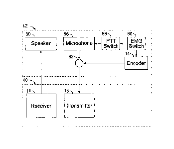
[0007] FIG. 1 is a simplified block schematic drawing of a speaker-
mic constructed in accordance with an embodiment of the present invention and
attached to an analog FM transceiver.
-2-
CA 02640027 2008-09-30
E-M0-00098 CA
[0008] FIG. 2 is a drawing of a speaker-mic constructed in
accordance with an embodiment of the present invention attached to an analog
FM
transceiver.
[0009] FIG. 3 is an electronic schematic drawing of the speaker-mic
embodiment shown in FIG. 1.
[0010] FIG. 4 is a functional block schematic drawing of a speaker-
mic to illustrate functional operation in accordance with an embodiment of the
present
invention.
DETAILED DESCRIPTION OF THE INVENTION
[0011] As used herein, an element or step recited in the singular and
proceeded with the word "a" or "an" should be understood as not excluding
plural said
elements or steps, unless such exclusion is explicitly stated. Furthermore,
references
to "one embodiment" of the present invention are not intended to be
interpreted as
excluding the existence of additional embodiments that also incorporate the
recited
features. Moreover,
unless explicitly stated to the contrary, embodiments
"comprising" or "having" an element or a plurality of elements having a
particular
property may include additional such elements not having that property.
[0012] FIG. 1 is a simplified block schematic drawing of a speaker-
microphone apparatus (speaker-mic) 12 constructed in accordance with an
embodiment of the present invention and attached to an analog FM transceiver
10.
Transceiver 10 comprises a receiver 11 and a transmitter 13. Through an
external
connection with an external speaker-microphone 12, hereafter speaker-mic 12,
receiver 11 transfers audio to a speaker 30 within speaker-mic 12. A
microphone 56,
controlled by a push-to-talk (PTT) switch 58, produces audio that is sent to
and
modulates FM analog transmitter 13, via connector 62, when PTT switch 58 is
pressed. An emergency switch 60 is also provided that activates microphone 56
(e.g.,
in some embodiments, by interacting with PTT switch 58). However, emergency
switch 60 further activates an encoder 14 that produces a signal that also
modulates
-3-
CA 02640027 2008-09-30
E-M0-00098 CA
transmitter 13 via the connector 62 in a manner described below. It should be
noted
that other switches or buttons may be configured to provide the functionality
of the
various embodiments of the invention.
[0013] More particularly, in various embodiments of the present
invention and referring to FIG. 2, an analog FM transceiver 10 is used for
transmitting
digital signaling information (e.g., MDC-1200 frequency shift keyed [FSK]
signaling
information) without requiring modification to transceiver 10. Instead, and
referring
to FIGS. 2 and 3, the speaker-mic apparatus 12 is used for transmit signal
operations
and a speaker output is used for receive signal operations. In some
embodiments of
the present invention, an off-the-shelf encoder module 14, such as an MDC-1200
encoder module is used. For example, encoder module 14 is encased in an
otherwise
standard speaker-mic 12 (an external option used for analog FM transceiver 10)
to
generate MDC-1200 signaling. Thus, these embodiments of the present invention
do
not require modifications, changes, rework, or an optional slot to implement
MDC-
1200 proprietary signaling on analog FM transceivers 10.
[0014] Speaker-mic 12 is configured to be compatible with typical
frequency responses for the analog FM transceiver 10 through external level
adjustments, whereas in at least one known prior art product in which encoder
module
14 is internal to transceiver 10, compatibility was maintained using internal
circuits,
software, or modules together with the internal radio level adjustments. By
contrast,
embodiments of the present invention provide digital signaling without any
need to
change or modify an existing transceiver 10. What appears to transceiver 10 as
a
standard speaker-mic 12 option is additionally capable of digital signaling,
such as
MDC-1200 digital signaling, transparent to the operation and functionality of
the
transceiver 10 (e.g., standard FM transceiver). Hereinafter, and without loss
of
generality, MDC-1200 digital encoding is assumed to be used in the exemplary
embodiments, even though other embodiments may use different types of
encoding.
Also, encoder module 14 is assumed to be an MDC-1200 encoder module in the
exemplary embodiments. An off-the-shelf encoder module (e.g., CIM-1000,
-4-
CA 02640027 2008-09-30
E-M0-00098 CA
manufactured by Cimarron Technologies Corp.) may be used for the encoder
module
14.
[0015] In some exemplary embodiments of the present invention, a
standard, unmodified speaker-mic, MIA-COM P7100 speaker-mic (either with or
without an antenna), can be modified for use. In some other embodiments of the
present invention, an unmodified speaker-mic, MIA-COM P7100 speaker-mic,
intrinsically-safe version, no antenna, vehicular charger version can be
modified for
use. A difference between these two microphones is that in the latter, there
is no RF
antenna output 16 on the speaker-mic for an antenna to attach to the speaker-
mic
itself. The use of an RF antenna output 16 can be advantageous when radiation
from
an antenna on transceiver 10 is blocked by a human body, as it is, for
example, when
transceiver 10 is clipped to a belt.
[0016] In various exemplary embodiments of the present invention,
MDC-1200 encoding is accomplished by injecting a signal on line 18 (via line
26)
from encoder module 14 directly onto the mic audio line 20 of speaker-mic 12.
Microphone (mic) audio from mic audio line 20 is processed by transceiver 10
through the standard analog FM transmitter path of transceiver 10 (e.g., pre-
emphasis
filter, limiter, post-limiter filter), and the MDC-1200 signaling 18 is sent
through this
same path regardless of the type of signaling being employed.
[0017] Encoder module 14 is used in speaker-mic 12 to permit
MDC- 1200 signaling. The connections to encoder module 14 include: power 22
and
ground 24 supply lines used to power encoder module 14; a data line 26 used to
generate the MDC-1200 signaling to be coupled onto mic audio input 20; a
sidetone
output 28 used to generate a local sidetone to speaker 30 indicating the
generation of
the MDC-1200 signaling during the beginning of a transmission; a microphone
mute
output 32 used to mute mic audio 20 during MDC-1200 signaling and prevent
voice
falsing; an emergency input 34 (e.g., emergency switch 60) used for emergency
automatic number identification (ANI) over the MDC-1200 signaling; push-to-
talk
(PTT) input 36 (e.g., PTT switch 58) used to initiate transmissions with the
MDC-
-5-
CA 02640027 2008-09-30
E-M0-00098 CA
1200 signaling preceding the voice; and key output 37 used to generate PTT
input 36
back to transceiver 10. Moreover, as shown in FIG. 3, an optional resistor
R108 can
be used to route PTT switch S1 input to transceiver 10 as well as encoder
module 14,
and to bypass the delayed routing of PTT input 36 from encoder module 14 to
transceiver 10. Power input 22 to encoder module 14, is the same as the power
supply
to speaker-mic 12. This power supply is operated, for example, at a nominal
7.5
volts.
[0018] MDC-1200 signaling data line 26 is coupled into the mic
audio path through resistor R103. Capacitor C101 performs deemphasis filtering
to
compensate for preemphasis filtering in transceiver 10, which is a basic radio
processing on the mic audio. The values of R103 and C101 set a nominal
signaling
level of encoder module 14 onto mic audio path 20.
[0019] Microphone mute output 32 drives MOSFET transistor Q102
to float mic audio return line 48 during MDC-1200 signaling. The float of mic
audio
return line 48 disables any unintentional mic audio, which would otherwise
corrupt,
interfere with, and/or override the MDC-1200 signal. Resistor R105 supplies
bias and
is used to activate MOSFET transistor Q102 for mic voice audio when MDC-1200
signaling is not active. An optional resistor may be provided to enable mic
audio at
all times (e.g., provides a "hot mic"), but may affect MDC-1200 signaling if
sufficient
background noise is present. Further, optional circuitry located on the
auxiliary input
to the encoder 14 includes at least resistor R112 and can be provided to hold
off
MDC-1200 signaling for some transceiver applications and modes (e.g.,
trunking).
[0020] Sidetone output 28 is coupled into audio amplifier 50 (IC1) of
speaker-mic 12 through resistor R104. The value of R104 sets the level of the
nominal sidetone to the speaker. PTT input 36 is sent to encoder module 14 (as
well
as the PTT input 52 of transceiver 10, if an optional resistor R109 is
installed),
allowing transceiver 10 to start a transmission, and allowing encoder module
14 to
start the MDC-1200 signaling at the beginning of each transmission from
transceiver
10.
-6-
CA 02640027 2008-09-30
E-M0-00098 CA
[0021] Emergency input 34 is sent to encoder module 14, allowing
the MDC-1200 signaling to include emergency ID information. Non-emergency
MDC-1200 signaling can include an ANI ID. Optionally, resistor R106 may be
included to allow transceiver 10 to override the MDC-1200 emergency signaling
with
other transceiver dependent emergency signaling formats.
[0022] The specific identification of the speaker-mic 12 is changed
via resistor R107 (8-UDL). Transceiver 10 reads resistor identifier R107 and
enables
battery power (7-BATT) to speaker-mic 12 at all times. A fixed resistor of,
for
example, 470 ohms is sensed by transceiver 10 for speaker-mic 12 operation.
Resistor R107 enables speaker-mic power at all times, whereas without resistor
R107,
speaker-mic power is provided only when speaker audio is expected.
[0023] Circuitry comprising transistor Q101, resistors R101 and R102
are controlled by a speaker-mute control 54 (Rx Mute) to mute speaker
amplifier 50
when all speaker audio is to be turned off. Optional resistor R110 can be used
to
enable audio amplifier 50 for test purposes only. Audio amplifier 50 amplifies
low
level audio 70 from transceiver 10 and also drives internal speaker 30 and
external
headset audio provided through a jack 64 or 66 (routed through a connector
J1).
Audio amplifier 50 is enabled via transistor Q101 and associated circuitry,
and is
controlled by RX MUTE line (J3-5) of transceiver 10. Mic audio from internal
microphone 56 is routed directly to transceiver 10 (J3-4). Transistor Q102 and
associated circuitry is capable of muting mic audio during transmissions of
MDC-
1200 signaling.
[0024] Switch 72 (SW1) can provide an audio gain control (high gain
or low gain) by manual switching in one of two gain resistor settings (R1 or
R2) in the
audio path from transceiver 10 to audio amplifier 50. Coupling capacitor Cl
blocks a
DC component on the audio from transceiver 10. RF bypass capacitors C21-C27,
C10-C13, and C3-C8 are used in the illustrated embodiment to eliminate
possible RF
(radio frequency) coupling into the circuits.
-7-
CA 02640027 2008-09-30
E-M0-00098 CA
[0025] It should be noted that encoder module 14 is programmed via
a separate programming input/output line 75, Prog1/0. Line 75 is bidirectional
(input
and output) and is used in conjunction with a programming cable 70 (e.g., CIM-
CABLE) that may be obtained from the supplier of encoder module 14.
Programming
is routed through the cable 70 via programming connector jack 64 (J4)
[0026] In some embodiments of the present invention, encoder
module 14 is programmed through programming connector jack 64, which may be an
earphone phono jack on speaker mic 12 (headset audio is eliminated, and a
programming cable 70, which may include a phono plug, is used only for
programming encoder module 14). For example, in one embodiment jack 64 may be
configured as headset audio output when a head set cable 68 (which may include
a
stereo plug) is plugged into jack 64 and as a headset audio output when a
monophonic
plug 70 is plugged into jack 64. In some embodiments, however, jack 64 is
configured as a programming port, and a separate audio jack 66 is provided for
headset audio output.
[0027] One suitable manner in which the encoder module 14 can be
programmed in speaker-mic 12 is via connection to a serial port of a personal
computer. A terminal program such as "HyperTerminal" may be used. The
HyperTerminal application is supplied in many versions of Microsoft Windows.
[0028] Settings that can be programmed for embodiments of the
present invention include the automatic number identification (ANI) ID and the
emergency (EMR) ID, which can be the same. Other settings are push to talk
(PTT)
sidetone, which can be set to "Y" (yes) of "N" (no). The attack time also can
be
changed (e.g., from 300 ms to 150 ms). Attack time generally refers to the
time
between (i) when a signal at the input of a device or circuit exceeds an
activation
threshold of the device or circuit and (ii) when that device or circuit reacts
in a
specified manners or to a specified degree to the input. The transmit (TX)
mode
additionally can be set as either conventional or trunking, as appropriate.
After
programming, the cable is unplugged and the radio power is cycled.
-8-
CA 02640027 2008-09-30
E-M0-00098 CA
[0029] In another embodiment of the present invention, the settings
applied are the same as those indicated above, except that a time-out timer
(TOT) is
set to 000 seconds (thereby disabling the TOT), with the attack time changed
(e.g., set
to 300 ms, which is the carrier attack time for the system including the radio
transceiver plus repeater), and KeyFollowsPTT is set to YES, so that the key
out to
the transceiver follows the PTT input to encoder module 14. A separate KEY
line to
the transceiver can also permit MDC-1200 signaling at the end of a
transmission. It
should be noted that the settings may be changed to correspond to different
operations
or different settings may be provided to control different operations.
[0030] Speaker-mic 12 may further include microphone mute
circuitry (e.g., Q102) and a mic audio return line 48, wherein microphone mute
circuitry is configured to control the mic audio return line during
transmission of a
digital identification signal, a digital emergency signal, or both, so that
mic audio does
not interfere with the digital identification signal, the digital emergency
signal, or
both. Speaker-mic 12 may further include an antenna jack 16 mounted on the
apparatus. In some embodiments of the method, a mic audio return line 48 is
adjusted
during transmission of a digital identification signal, a digital emergency
signal, or
both, so that mic audio does not interfere with the digital identification
signal, the
digital emergency signal, or both.
[0031] In other embodiments, software in speaker-mic 12 can be
provided to initiate MDC signaling via a PTT line from the transceiver.
Normally,
PTT is an input to the transceiver, but PTT can be converted to an output for
MDC
signaling activation. Also, MDC signaling can be initiated via an emergency
line
from the transceiver. Normally, "emergency" is an input to the transceiver,
but it can
be converted to an output for MDC signaling activation. Also, the transceiver
may
have a UDC Tx line that can be used to enable and/or disable the MDC signaling
under various conditions, e.g., trunked mode operation, priority overrides,
etc.
[0032] FIG. 4 is a functional block schematic drawing of speaker-
mic 12 to illustrate functional operation of an exemplary embodiment of the
present
-9-
CA 02640027 2008-09-30
E-M0-00098 CA
invention. As shown, speaker-mic 12 is an external speaker/microphone
apparatus for
a radio transceiver 10. Radio transceiver 10 includes a connector 120 for
connection
to the speaker-mic 12. Speaker-mic 12 includes speaker 30, microphone 56, push-
to-
talk (PTT) switch 58, and an emergency switch 60. Encoder module 14 (of any
suitable type) is operatively coupled to PTT switch 58 and emergency switch 60
so
that, in operation, a digital identification 144 is generated each time PTT
switch 58 is
pressed, and a digital emergency signal 142 is generated when emergency switch
60 is
pressed. For example,
encoder module 14 continuously generates digital
identification signal 32 and emergency signal 142. When PTT switch 58 is
pressed,
audio from microphone 56 is added at audio summer 122 to digital
identification
signal 144 to generate an audio signal 84 that is coupled to connector 62 via
PTT
switch 58, summer 104, and output level controller 106. The output of output
level
controller 106 is a combination audio signal, which in various embodiments is
the mic
audio 20. When emergency switch 60 is pressed, audio signal 84 is combined
with
emergency signal 142 by audio summer 96 and coupled to connector 62 via
emergency switch 60, audio summer 104, and output level controller 106. "Or"
gate
94 serves to operatively couple PTT switch 58 and emergency switch 60 to
connector
62 so that PTT output 116 is activated and transceiver 10 is switched to a
transmit
mode when either PTT switch 58 or emergency switch 60 is pressed.
[0033] In some embodiments of the present invention, additional
features may be added to emergency switch 60. For example, emergency switch 60
may be coupled via a logic line 140 to encoder module 14 to enable only the
generation of the emergency signal 142 and not the identification signal 144
when
emergency switch 60 is pressed. Also, when emergency switch 60 is pressed,
encoder
module 14 may mute speaker 30 (and/or microphone 56, although not shown in
FIG.
4) via mute output 32. Although not shown in FIG. 4, any or all of these
additional
features may be added to PTT switch 58 either in addition to, or instead of
being
added to emergency switch 60.
-10-
CA 02640027 2008-09-30
E-M0-00098 CA
[0034] In some embodiments of the present invention, de-emphasis
filters 130 are added in emergency signal line 142 and/or identification
signal line
144. Also, an RF signal 118 from transceiver 10 is used to apply power to RF
antenna output 16, such as an RF jack, on speaker-mic 12 to power an antenna
80
located thereon. Additional jacks or ports 64 and 66 are provided to program
encoder
module 14 and to output speaker audio, respectively.
[0035] It will be appreciated that some embodiments of the present
invention provide digital signaling without requiring specialized circuitry
and
software built into the analog FM transceiver, and can be added to existing
transceivers without altering the internal wiring of the transceiver itself.
[0036] To the extent that the figures illustrate diagrams of the
functional blocks of various embodiments, the functional blocks are not
necessarily
indicative of the division between hardware circuitry. Thus, for example, one
or more
of the functional blocks (e.g., processors or memories) may be implemented in
a
single piece of hardware (e.g., a general purpose signal processor or a block
of
random access memory, hard disk, or the like). Similarly, the programs may be
stand
alone programs, may be incorporated as subroutines in an operating system, may
be
functions in an installed software package, and the like. It should be
understood that
the various embodiments are not limited to the arrangements and
instrumentality
shown in the drawings.
[0037] Accordingly, it is to be understood that the above description
is intended to be illustrative, and not restrictive. For example, the above-
described
embodiments (and/or aspects thereof) may be used in combination with each
other. In
addition, many modifications may be made to adapt a particular situation or
material
to the teachings of the invention without departing from its scope.
Dimensions, types
of materials, orientations of the various components, and the number and
positions of
the various components described herein are intended to define parameters of
certain
embodiments, and are by no means limiting and are merely exemplary
embodiments.
-11-
CA 02640027 2015-07-17
Many other embodiments and modifications within the scope of the claims
will be apparent to those of skill in the art upon reviewing the above
description.
[0038] The scope of the various embodiments of the invention
should, therefore, be determined with reference to the appended claims, along
with
the full scope of equivalents to which such claims are entitled. in the
appended
claims, the terms "including" and "in which" are used as the plain-English
equivalents
of the respective terms "comprising" and "wherein." Moreover, in the following
claims, the terms "first," "second," and "third," etc. are used merely as
labels, and are
not intended to impose numerical requirements on their objects.
-12-