Sélection de la langue

Search

Sommaire du brevet 2640810 

Énoncé de désistement de responsabilité concernant l'information provenant de tiers

Une partie des informations de ce site Web a été fournie par des sources externes. Le gouvernement du Canada n'assume aucune responsabilité concernant la précision, l'actualité ou la fiabilité des informations fournies par les sources externes. Les utilisateurs qui désirent employer cette information devraient consulter directement la source des informations. Le contenu fourni par les sources externes n'est pas assujetti aux exigences sur les langues officielles, la protection des renseignements personnels et l'accessibilité.

Disponibilité de l'Abrégé et des Revendications

L'apparition de différences dans le texte et l'image des Revendications et de l'Abrégé dépend du moment auquel le document est publié. Les textes des Revendications et de l'Abrégé sont affichés :

  • lorsque la demande peut être examinée par le public;
  • lorsque le brevet est émis (délivrance).
(12) Demande de brevet: (11) CA 2640810
(54) Titre français: COLLIER DE LAMPES
(54) Titre anglais: LIGHT COLLAR
Statut: Réputée abandonnée et au-delà du délai pour le rétablissement - en attente de la réponse à l’avis de communication rejetée
Données bibliographiques
(51) Classification internationale des brevets (CIB):
  • F21V 07/04 (2006.01)
(72) Inventeurs :
  • RISING, PETER E. (Etats-Unis d'Amérique)
  • REMMER, JOHN (Etats-Unis d'Amérique)
(73) Titulaires :
  • PETER E. RISING
  • JOHN REMMER
(71) Demandeurs :
  • PETER E. RISING (Etats-Unis d'Amérique)
  • JOHN REMMER (Etats-Unis d'Amérique)
(74) Agent: BORDEN LADNER GERVAIS LLP
(74) Co-agent:
(45) Délivré:
(86) Date de dépôt PCT: 2007-02-05
(87) Mise à la disponibilité du public: 2007-08-16
Requête d'examen: 2012-02-03
Licence disponible: S.O.
Cédé au domaine public: S.O.
(25) Langue des documents déposés: Anglais

Traité de coopération en matière de brevets (PCT): Oui
(86) Numéro de la demande PCT: PCT/US2007/003046
(87) Numéro de publication internationale PCT: US2007003046
(85) Entrée nationale: 2008-07-30

(30) Données de priorité de la demande:
Numéro de la demande Pays / territoire Date
60/765,308 (Etats-Unis d'Amérique) 2006-02-03

Abrégés

Abrégé français

Cette invention concerne un collier de lampes présentant un diamètre extérieur, un premier diamètre intérieur, un deuxième diamètre intérieur supérieur au premier diamètre intérieur formant un alésage permettant d'introduire un tube d'ampoule et au moins un orifice dans une surface extérieure du collier présentant une profondeur permettant d'introduire une source de lumière.


Abrégé anglais


A light collar includes an outside diameter, a first inside diameter, a second
inside diameter greater than the first inside diameter forming a bore for
receiving an ampoule well, and at least one port in an outer surface of the
collar having a depth for receiving a light source.

Revendications

Note : Les revendications sont présentées dans la langue officielle dans laquelle elles ont été soumises.


What is claimed is:
1. A light collar formed of a material for diffusing light and
formed in a shape of a ring comprising:
an outer surface having an outside diameter;
an inner surface a first inside diameter and a second
inside diameter greater than the first inside diameter forming a
bore for receiving an ampoule well; and
at least one port in an outer surface of the collar having
a depth for receiving a respective light source.
2. The light collar of claim 1, wherein the material is one of
Butyrate and Polybutyrate.
3. The light collar of claim 1, coupled to an ampoule well.
4. The light collar of claim 1, wherein each light source is
imbedded in the respetive at least port at a depth sufficient to
create a halo when each light source is in an on state.
5. The light collar of claim 1, wherein each light source is
sealed in the port.
6. The light collar of claim 1, wherein an interface between
the light collar and each light source is wetted.
9

7. The light collar of claim 1, wherein the at least one port
is positioned in a geometric location, wherein depending on a
number of light sources, have a substantially equal arc of a
circle between the at least one port.
8. The light collar of claim 1, wherein the light source is
friction fit in the at least one port.

Description

Note : Les descriptions sont présentées dans la langue officielle dans laquelle elles ont été soumises.

CA 02640810 2008-07-30
WO 2007/092387 PCT/US2007/003046
LIGHT COLLAR
CROSS-REFERENCE TO RELATED APPLICATIONS
This application claims priority to U.S. Provisional
Application Serial Nos. 60/765,308, filed on February 3, 2006,
which is herein incorporated by reference in its entirety.
BACKGROUND OF THE INVENTION
1. Technical Field:
The present invention relates to a system for analyzing the
conterits of an ampoule, and more particularly to a collar for
directing light into the ampoule.
2. Discussion of Related Art:
For certain applications, such as high volume testing (500-
3000 tests per day) bacteria in urine analysis, a sample vessel
containing urine (IME.TESTTm ampoule) needs to be inserted
multiple times (a start reading and a finish reading) so that
the entire batch of sample urines may be incubated
simultaneously for a fixed period of time. This batch
processing causes sample containers to be inserted once for an
initial start of test reading and a second time for an end of
test reading. If sample container is not inserted into the
instrument performing the light transmission reading in the
exact same rotational registration as the first measurement, a
1

CA 02640810 2008-07-30
WO 2007/092387 PCT/US2007/003046
resulting reading can vary by as much as 50% (+/-). This
rotational variation can render the comparison between the first
and second readings meaningless. The variation in reading is
caused by the variation of the sample container, particularly if
said container has a conical shape at the top associated with an
ampoule sealing technique (IME.TESTTM ampoule). Additionally,
the large testing volume associated with each batch
substantially prevents the test operator from taking the time
that may be needed for the sample insertion process and manual
alignment to a fixed registration mark.
Therefore, a need exists for a light collar for controlling
the dispersion of light into an ampoule within a light
transmission analysis device.
SUM+SpiRY OF THE INVENTION
According to an embodiment of the present disclosure, a
light collar includes an outside diameter, a first inside
diameter, a second inside diameter greater than the first inside
diameter forming a bore for receiving an ampoule well, and
at least one port in an outer surface of the collar having a
depth for receiving a light source.
BRIEF DESCRIPTION OF THE DRAWINGS
Preferred embodiments of the present invention will be
2

CA 02640810 2008-07-30
WO 2007/092387 PCT/US2007/003046
described below in more detail, with reference to the
accompanying drawings:
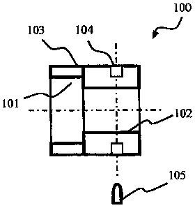
FIG. 1 is a diagram of a light collar according to an
embodiment of the present disclosure;
FIG. 2 is a diagram of a light collar fitted to an ampoule
well according to an embodiment of the present disclosure; and
FIG. 3 is a diagram of a system according to an embodiment
of the present disclosure.
DETAILED DESCRIPTION OF PREFERRED EMBODIMENTS
According to an embodiment of the present disclosure, a
device scatters light emission to substantially eliminate
rotational bias effects of formed ampoules (IME.TESTTM ampoule).
The scattered light is substantially even and at a specific
stage height such that measurements may be taken at specific
wave length light transmission percentages over multiple ampoule
insertions as done by the IME.TESTTM Autoanalyzer.
Referring to Figure 1, according to an embodiment of the
present disclosure, a method for forming a collar comprises
cutting, transaxially, a translucent tube formed of, for
example, Butyrate or Polybutyrate, into sections suitable for
mounting in a light measuring device such as the IME.TESTTM
Autoanalyzer. The resulting section 100, called a collar, is
machined to form a bore 101 on an inner surface 102. An outer
3

CA 02640810 2008-07-30
WO 2007/092387 PCT/US2007/003046
surface 103 of the collar 100 is partially ported with one or
more holes 104 suitable for the insertion of a desired light
source (e.g., an LED). A lens of a light is imbedded in the
collar 100 at a depth sufficient to create a halo when the light
is in an on state. The light is sealed in the hole 104. An
interface between the collar and the lens of the light is
wetted, for example, by a glue for sealing the light. The
wetting substantially eliminates any effect of frosting of the
surface of the hole caused by the porting.
An exemplary collar 100 may have an outside diameter of
0.750 in. and an inside diameter of 0.500 in. The holes 104 may
be, for example, 0.100 in. deep and 0.125 in. wide. The collar
100 may be 0.750 in. high having a bore 101 0.300 in. deep. One
skilled in the art would recognize that other dimensions may be
used.
The holes 104 are positioned in a geometric location so
that, depending on the number of lights intended for use in the
collar, having a substantially equal arc of a circle between the
partial light ports 104. For example, a collar 100 having two
lights includes light ports located 180 degrees apart while a
collar having three light ports would have their locus 120
degrees apart.
After creation of the partial ports 104, wide lens light
sources 105 are imbedded into the collar 100, for example, as by
4

CA 02640810 2008-07-30
WO 2007/092387 PCT/US2007/003046
a gluing operation. Commercially available glues may be used.
The imbedded may alternatively include a friction fitting of the
light sources or a mechanical lock fixing the lights to the
collar. Once the imbedding has been completed the collar is
mounted in the analyzing instrument at the specific stage height
needed to perform light transmission into the sample container.
More particularly, the collar 100 is mounted to an ampoule well
200 having a depth for receiving an ampoule 201 such that the
collar is positioned at the desired stage height.
Light emitted by a light source coupled to the collar is
diffused around through the collar forming a halo of light.
Variations of light passing through the sample container due to
rotation caused by the irregularities of the sample container,
e.g., where a light source is disposed above the ampoule or to a
side of the ampoule, are reduced from greater than about 50% to
less than about 1% variation. The stage height of the light
emitter or focus point of the light on the sample is precisely
controlled, wherein the ampoule contacts a bottom of the well
and the height of the collar from the bottom is substantially
fixed. The distance between the collar including the light
emitter and the sample in the amouple is reduced for the
measurement application, e.g., the collar is disposed below a
height of the sample in the ampoule. In addition, the
opportunity for light source movement, damage or hindrance is
5

CA 02640810 2008-07-30
WO 2007/092387 PCT/US2007/003046
low.
The ampoule well further includes studs 202 disposed on an
outer sidewall for mounting the well to, for example, a circuit
board. Additional light sources may be mounted to the outer
sidewall of the ampoule well, for example, an infrared light
source.
According to an embodiment of the present disclosure, a
light collar may be implemented in conjunction with a liquid
testing system includes a first well for receiving a sample to
be tested, a first light source for illuminating the first well
with light having a first wavelength, and a second light for
illuminating the first well with light having a second
wavelength. At least one of the first light source and the
second light source are imbedded in the light collar. The liquid
testing system further includes a light control, coupled to the
first light source and the second light source, for selecting
one of the first light source or the second light source to
illuminate the first well, a light detector receiving light
passing through the first well, and a processor, coupled to the
light control and the light detector, for determining a light
characteristic of the sample over time.
More particularly, referring to FIG. 3, a control circuit
of the liquid testing system includes a processor 301 coupled to
a heat control device 302, a light control device 303, and a
6

CA 02640810 2008-07-30
WO 2007/092387 PCT/US2007/003046
light detection device 304. The heat control device 302 controls
a heating element 305 for controlling an incubation temperature
of an ampoule well and its contents. The processor 301 receives
temperature information from a temperature sensor 306, which
forms a control loop with the processor 301, heat control device
302 and heating element 305 for controlling the temperature of
the ampoule well. The light control device 304 is coupled to a
light source, such as an ultraviolet light 307 or a visible
light 308. The light detection device 304 monitors light passing
through the test ampoule and any contents therein. A gain
control 309 can be adjusted to control a sensitivity of the
light detection device 304. Light information is passed to the
processor 301.
Individual wells of the system may be controlled using a
well specific heat control 302 and light control 303. Multiple
lights 307-308 may be provided for each well. Likewise, multiple
heating elements 305 may be provided for each well. Thus, the
same or different tests may be preformed in different wells
simultaneously. For example, one or more temperature profiles
can be run simultaneously. Further still, different light
sources can be used for different ampoules. Thus, for example,
a test for Escherichia coli can be performed in a first ampoule
well and a test for fecal Coliform can be performed in a second
ampoule well. Separate results may be provided for each test.
7

CA 02640810 2008-07-30
WO 2007/092387 PCT/US2007/003046
The processor 301 may be coupled to additional devices,
including, for example, an input device 309, such as a keypad, a
serial port 310, a memory device 311, a clock 312, and a display
313.
S Having described embodiments for a light collar, it is
noted that modifications and variations can be made by persons
skilled in the art in light of the above teachings. It is
therefore to be understood that changes may be made in the
particular embodiments of the invention disclosed which are
within the scope and spirit of the invention.
~

Dessin représentatif
Une figure unique qui représente un dessin illustrant l'invention.
États administratifs

2024-08-01 : Dans le cadre de la transition vers les Brevets de nouvelle génération (BNG), la base de données sur les brevets canadiens (BDBC) contient désormais un Historique d'événement plus détaillé, qui reproduit le Journal des événements de notre nouvelle solution interne.

Veuillez noter que les événements débutant par « Inactive : » se réfèrent à des événements qui ne sont plus utilisés dans notre nouvelle solution interne.

Pour une meilleure compréhension de l'état de la demande ou brevet qui figure sur cette page, la rubrique Mise en garde , et les descriptions de Brevet , Historique d'événement , Taxes périodiques et Historique des paiements devraient être consultées.

Historique d'événement

Description Date
Demande non rétablie avant l'échéance 2014-02-05
Le délai pour l'annulation est expiré 2014-02-05
Réputée abandonnée - omission de répondre à un avis sur les taxes pour le maintien en état 2013-02-05
Inactive : Correspondance - PCT 2012-03-01
Lettre envoyée 2012-02-22
Toutes les exigences pour l'examen - jugée conforme 2012-02-03
Exigences pour une requête d'examen - jugée conforme 2012-02-03
Requête d'examen reçue 2012-02-03
Inactive : Notice - Entrée phase nat. - Pas de RE 2009-02-04
Inactive : Page couverture publiée 2008-11-20
Inactive : Notice - Entrée phase nat. - Pas de RE 2008-11-18
Inactive : Inventeur supprimé 2008-11-18
Inactive : CIB en 1re position 2008-11-07
Demande reçue - PCT 2008-11-06
Inactive : Correspondance - PCT 2008-08-21
Exigences pour l'entrée dans la phase nationale - jugée conforme 2008-07-30
Demande publiée (accessible au public) 2007-08-16

Historique d'abandonnement

Date d'abandonnement Raison Date de rétablissement
2013-02-05

Taxes périodiques

Le dernier paiement a été reçu le 2012-02-02

Avis : Si le paiement en totalité n'a pas été reçu au plus tard à la date indiquée, une taxe supplémentaire peut être imposée, soit une des taxes suivantes :

  • taxe de rétablissement ;
  • taxe pour paiement en souffrance ; ou
  • taxe additionnelle pour le renversement d'une péremption réputée.

Les taxes sur les brevets sont ajustées au 1er janvier de chaque année. Les montants ci-dessus sont les montants actuels s'ils sont reçus au plus tard le 31 décembre de l'année en cours.
Veuillez vous référer à la page web des taxes sur les brevets de l'OPIC pour voir tous les montants actuels des taxes.

Historique des taxes

Type de taxes Anniversaire Échéance Date payée
Taxe nationale de base - générale 2008-07-30
TM (demande, 2e anniv.) - générale 02 2009-02-05 2009-02-04
TM (demande, 3e anniv.) - générale 03 2010-02-05 2010-02-03
TM (demande, 4e anniv.) - générale 04 2011-02-07 2011-02-02
TM (demande, 5e anniv.) - générale 05 2012-02-06 2012-02-02
Requête d'examen - générale 2012-02-03
Titulaires au dossier

Les titulaires actuels et antérieures au dossier sont affichés en ordre alphabétique.

Titulaires actuels au dossier
PETER E. RISING
JOHN REMMER
Titulaires antérieures au dossier
S.O.
Les propriétaires antérieurs qui ne figurent pas dans la liste des « Propriétaires au dossier » apparaîtront dans d'autres documents au dossier.
Documents

Pour visionner les fichiers sélectionnés, entrer le code reCAPTCHA :


Pour visualiser une image, cliquer sur un lien dans la colonne description du document. Pour télécharger l'image (les images), cliquer l'une ou plusieurs cases à cocher dans la première colonne et ensuite cliquer sur le bouton "Télécharger sélection en format PDF (archive Zip)" ou le bouton "Télécharger sélection (en un fichier PDF fusionné)".

Liste des documents de brevet publiés et non publiés sur la BDBC .

Si vous avez des difficultés à accéder au contenu, veuillez communiquer avec le Centre de services à la clientèle au 1-866-997-1936, ou envoyer un courriel au Centre de service à la clientèle de l'OPIC.


Description du
Document 
Date
(aaaa-mm-jj) 
Nombre de pages   Taille de l'image (Ko) 
Description 2008-07-29 8 282
Abrégé 2008-07-29 1 49
Dessins 2008-07-29 2 20
Revendications 2008-07-29 2 38
Dessin représentatif 2008-11-18 1 4
Rappel de taxe de maintien due 2008-11-17 1 112
Avis d'entree dans la phase nationale 2008-11-17 1 194
Avis d'entree dans la phase nationale 2009-02-03 1 194
Rappel - requête d'examen 2011-10-05 1 117
Accusé de réception de la requête d'examen 2012-02-21 1 175
Courtoisie - Lettre d'abandon (taxe de maintien en état) 2013-04-01 1 173
Correspondance 2008-08-20 1 32
PCT 2008-07-29 1 48
Correspondance 2012-02-29 3 76