Note : Les descriptions sont présentées dans la langue officielle dans laquelle elles ont été soumises.
CA 02646552 2014-05-26
APPARATUS FOR AND METHOD OF INHIBITING DELAMINATION
Field of the Invention
The present invention relates to an apparatus for and method of
compressing a curved region of a laminated element or structure so as to
protect
the element or structure against delamination.
Background of the Invention
Fibre reinforced laminates offer considerable advantages in terms of
stiffness and durability when compared to many existing metallic materials. As
such they have found widespread use in many industries, and notably within the
manufacture of aircraft where the weight of the structure is of critical
importance.
There are, however, several intricacies when designing components of fibre
reinforced laminates. A predominant design consideration stems from the fact
that, within a final product, much of the load bearing performance is derived
from
the alignment of the fibres within the structure. In general, the structures
are
engineered such that the primary loads to be born by the structure act in a
longitudinal direction of layers of fibres.
A laminated structure is generally laid up by building up one layer of
fibres on preceding layers of fibres. Within each layer of fibre, all of the
fibres run
in the same direction. That is to say, each layer is not a weave of warp and
weft
fibres as this necessarily puts a crinkle in the fibres which reduces their
ability to
resist compressive loads. Alternate layers are laid in different directions,
generally
at 900 to one another, in order to produce a component. However, if one
considers, for simplicity, a planar panel made up of such layers of laminated
material, it can be seen that the panel can be made relatively strong with
regards
to forces acting in the plane of the panel, but there are no fibres running
1
CA 02646552 2014-05-26
perpendicular to the plane of the panel. Therefore the panel would be
relatively
weak in response to tension seeking to separate the layers of the panel from
one
another. This limitation is generally not significant when considering the
construction of planar elements, but becomes more significant when a laminated
element has a curve formed therein.
US 6415496 discloses a process for making a dismountable and/or
fixed traction-compression coupling to be applied to composite materials. A
laminate is folded to obtain a skirt. A set of distribution plates is applied
over the
laminate to stabilize the skirt and produce a uniform load distribution.
Traction
bolts obtain a connection between components to be joined.
US 5827383 discloses an improved stiffener reinforced assembly and
method. A stiffener is attached to a composite skin by inserting reinforcing
pins at
the radius region of the stiffener and into the skin material to increase the
initial
failure load of the joint between the stiffener and the skin material.
Summary of the Invention
According to a first aspect of the present invention there is provided a
combination of a laminated element having a curved portion with a first
surface
region following a first curved path and a second surface region opposed to
the
first surface region following a second curved path; and compression apparatus
for
compressing the curved region of the laminated element, wherein the
compression
apparatus comprises a first compression member which is placed against the
first
surface region and urged towards a second compression member placed against
the second surface region, in which one or more fasteners extend between the
first
and second members, and the fasteners are in tension, wherein at least one of
the
fasteners passes through the curved portion of the laminated element.
2
CA 02646552 2014-05-26
It is thus possible to clamp a curved region of a laminated element
between first and second compression members, which effectively act as jaws of
a
clamp, so as to ensure that the fibres in the curved portion of the laminated
element are always held in compression with respect to an adjacent layer of
fibres
for loads less than a predetermined maximum load.
Typically the curved region of the laminated element is defined so as
to form an interface between a wall of the element and a flange such that the
laminated element can be secured to an adjacent element. The curved region
may form a part cylindrical surface which may extend for some considerable
distance. Advantageously the first and second compression members are
elongate members such that one or more members may be placed against each of
the first and second surface regions in order to protect the curved region of
the
laminated element over a substantial portion, and preferably all, of its
length.
At least one fastener extends, in tension, between the first and
second compression members such as to urge them towards one another and
thereby to clamp the curved region of the laminated element therebetween.
The combination may further comprise a second element which can be joined to
the laminated element by a fastener such as a screw, bolt, rivet or adhesive.
Typically the laminated element has a flange which can be joined to the second
element. Preferably the flange is adapted to lie substantially parallel with a
surface
of the second element.
Typically the curved portion has a concave face on a first side of the
laminated element, and a convex face on a second side of the laminated
element,
and the second element is adapted to be joined to the laminated element on its
second side.
3
CA 02646552 2014-05-26
According to a second aspect of the present invention there is
provided a method of protecting a curved region of a laminated element against
delamination, the method comprising placing a first member against a first
surface
of the curved region and placing a second member against a second surface of
the curved region, said first and second surfaces being on opposed sides of
the
curved region, and urging the first and second members together so as to place
the curved region therebetween under compression, wherein one or more
fasteners extend between the first and second members, and the fasteners are
in
tension, wherein at least one of the fasteners passes through the curved
region of
the laminated element.
Brief Description of the Drawings
The present invention will further be described, by way of example
only, with reference to the accompanying drawings, in which:
Figure 1 schematically illustrates how forces acting within the plane
of a first laminated element can give rise to delamination forces in a curved
region
of that element;
Figure 2 shows a prior art solution.
Figure 3 is a plan view of a compression apparatus constituting an
embodiment of the present invention; and
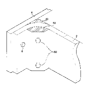
Figure 4 is a perspective view showing the apparatus of Figure 3 in
use so as to facilitate joining of a wing spar to a wing surface.
Description of Preferred Embodiments of the present Invention
Figure 1 schematically illustrates an interface between a first
laminated element, generally designated 2 and a second element 4. The second
element 4 may or may not be laminated. The elements 2 and 4 are attached
4
CA 02646552 2014-05-26
together by a plurality of fasteners, of which one fastener 6 is shown for
simplicity.
The fastener may be any suitable fastener for holding the elements 2 and 4
together in order to resist relative motion therebetween in response to loads
acting
between the elements 2 and 4. Suitable fasteners may include, without
limitation,
screws, bolts, rivets and adhesive. The element 2 has a curved region 10 with
a
concave face on a first side of the element 2, and a convex face on a second
side
of the element 2. The element is 4 joined to the element 2 on its second side
(that
is, on the same side as the convex face). Suppose, for the sake of discussion,
the
fastener 6 is a bolt, optionally with a counter sunk head so as to leave a
smooth
outer surface, and that a load is expected to act in the directions A or B
such that
the load is substantially perpendicular to the panel 4 and acts substantially
within
the plane of a non-curved region 8 of the panel 2. However it will be seen
that in
the curved region, generally designated 10, of the panel 2 then the forces
within
the panel will not lie along the local axis of the fibres within the panel.
Although the panel 2 is solid, it is instructive to consider the effects of
a load acting only on the innermost and outermost surfaces of the panel 2. The
curved region of the panel can be considered as extending between a first
chain
line 12 and a second chain line 14. it could be seen that the length, LI, of
the
fibres extending between the lines 12 and 14 on an innermost surface 16 of the
panel is less than the distance L0 of fibres extending between the same lines
12
and 14 on an outermost surface 18 of the panel.
It can be seen, intuitively, that if a force where to act along the
direction C so as to attempt to straighten the curved region 10 of the panel,
then
as the curve was removed from the panel, that is to say the curve is "opened"
out
from its manufactured angle, the distances between the lines 12 and 14 along
the
5
CA 02646552 2014-05-26
inner surface and outer surface would tend to equalise. However the fibres
resist
extension or compression and this gives rise to a force, acting along the
direction
of arrow F, which urges the adjacent layers of the composite material to
separate
from one another. This force is referred to as a "through thickness tensile
load
and places the resin holding adjacent layers of the laminate into tension, and
if the
forces exceed the tensile strength of the resin then the laminated product
will
delaminate. The matrix of material within the laminate is not reinforced along
directions normal to its surface, and hence its ability to resist this
delaminating
force is poor compared to the strength within the local plane of the laminated
product. It is less intuitive, but nevertheless a fact, that the forces acting
in the
directions A or B will also give rise to similar effects as the force will act
either to
open or close the curve from its manufactured shape and can give rise to both
actions occurring simultaneously at different points of the curve. The reader
may
observe this by folding a pad of paper to follow a curved path similar to that
shown
in Figure 1, then applying forces along directions A or B, as appropriate. As
the
forces are applied (bearing in mind that position of the planar portion 8 of
the panel
2 is generally inhibited from moving laterally) then the radii of curvature
change
slightly leading to parts of the curve experiencing compressive forces acting
between the inner and outer faces and other parts of the curve experiencing
tensile forces acting between the inner and outer faces.
This problem of controlling internal loads generated within a corner
radius of a laminate structure reacting against an applied load is known and
solutions have been proposed in the prior art so as to overcome this. One such
solution is the inclusion of individual washers which extend from the
fastener, into
the "throat" 28 of the corner radii, as shown in Figure 2, in an attempt to
transfer
6
CA 02646552 2014-05-26
the load closer to the planar (vertical section shown in Figure 2) of the
joint. Thus,
in this example, the washer 30 has a non-circularly symmetric profile and has
a
portion 32 which extends towards the curved surface 34 of the laminated
element
2. The washer is profiled so as to match the curved surface 34 thereby
transferring the load into the vertical section of the laminated element. In
Figure 2
the washer and the elements 2 and 4 are shown as being held together by a bolt
36 cooperating with a nut 38. This solution can be seen to be only partiaily
successful, and can only be applied to joints having through fasteners such as
bolts or screws. It does not work with bonded joints.
A further prior art attempt to protect the curved region of the element
2 against delamination is to insert "Z pins" through the laminated material.
These
are effectively short sections of fibre which extend substantially
perpendicular to
the normal of the local surface of the laminated element in an attempt to
increase
its strength in the direction perpendicular to the local surface. However the
Z pins
are themselves only secured to the laminated structure by the resin used to
bond
the structure together and consequently the maximum force which can be
absorbed by a Z pin varies as a function of distance from the surface of the
laminated structure. This is because, as with any fibre reinforced material,
the
efficiency of the reinforcement is proportional to the length of the fibres.
Thus,
within a thin section of laminate, Z pins are not long enough to fully absorb
and
react against the load tending to delaminate the material. Additionally when Z
pins
are inserted into the laminate they create a distortion of the existing fibres
which
can lead to performance for degradation within the laminate as a whole and
which
degradation is also proportional to the thickness of the laminate.
7
CA 02646552 2014-05-26
In order to avoid the risk of delamination, the inventor has realised
. that the curved portion of the laminated structure should be preloaded into
compression such that adjacent layers of the laminated structure are forced
towards one another. As a consequence of this internal forces within the
structure
tending to urge the adjacent layers apart now have to act against the
compressive
preload thereby absorbing all (or at least substantially reducing) the through
thickness loads generating by any "opening" of the corner.
In order to provide a preload a first compression member 40 is
provided on the convex side of the curved region 10 of the member 2, and a
second compression member 50 is placed on the concave side of the curved
region. The first compression member has a generally cylindrical-concave
surface
42 adapted to closely match the corresponding radius of curvature of the
convex
outer face 18 of the member 2. Advantageously any manufacturing tolerances
should be set such that the radius of curvature of the concave face is
marginally
greater than the radius of curvature of the convex outer face 18 in the curved
region such that any gap therebetween may be filled with a filler, such as a
resin
and particulate mix, thereby ensuring uniform load transfer between the first
compression member 40 and the outermost face 18 of the laminated element.
The second compression member 50 has a cylindrical convex face 52 which
substantially matches the radius of curvature of the inwardly directed concave
curved surface 54 of the element 2. Here any manufacturing tolerance should
err
on the side of the convex surface having a slightly smaller radius of
curvature than
the concave surface 54 such that any gaps therebetween can be filled with a
filler.
The first and second compression members may be elongate extrusions, as
shown in Figure 4. The first and second compression members are urged into
8
CA 02646552 2014-05-26
engagement with the respective cooperating surfaces of the laminated element 2
by a plurality of fasteners 60 which extend under tension through respective
channels, such as drill holes, extending through the first compression member
40,
the second compression member 50 and the curved portion of the laminated
structure disposed therebetween.
The or each tension fastener may, for example, be a bolt or a screw.
The bolt may engage with an externally provided nut or may engage with a
threaded portion of one of the compression members. As shown in Figure 3 a
washer 62 may be disposed between a head of a bolt 64 and either one of the
compression members 40 or 50, as appropriate, in this example the second
compression member 50, so as to spread the compressive forces more evenly
within the compression members 40 and 50. The first compression member 40
shown in Figure 3 is provided with an internally threaded face in the passage
therein so as to engage with the threads on the bolt
The compression members 40 and 50 may be made out of any
suitable material, and thus for example could be formed out of an extruded
metal.
Aluminium represents a suitable candidate material. However, they can
conveniently be made from fibre reinforced laminate with the longitudinal
direction
of the fibres being parallel to the longitudinal axis of the compression
member (that
is up and down the direction shown in Figure 4). Making the compression
members from fibre reinforced laminate has the advantage of reducing galvanic
corrosion of the metal fixings used to secure the compression members either
side
of the laminated element 2.
The compression members can be regarded as reinforcement
elements and can themselves aid the interface with the joint itself. Thus, if
we look
9
CA 02646552 2014-05-26
at Figure 4, the compression member 40 abuts the element 4 and as such can aid
load transfer between element 2 and element 4. Furthermore, if adhesive is
used
between compression member 40 and elements 2 and 4, then the overall strength
of the joint is increased.
The placement (number, size and interfastener distance) of the
fasteners 60 is determined by the local loads - and hence the degree of
preload
required. Consequently similar size compression members can be used over
widely varying load ranges provided that an appropriate number of fasteners
are
used for the expected load.
The compression members are placed around the element 2 after the
element has been formed - and preferably after the resin has cured. Thus the
action of drilling the through holes does not disrupt the fibre alignment
within
laminate - except in the region of the hole itself. As a result of the overall
integrity
of the laminated component is not too adversely affected, and the performance
of
the combination of the component 2 and its compression arrangement should be
significantly better than that of an equivalent unmodified component 2 alone.
The invention is particularly suited for use in the aerospace sector.
The element 2 may, for example, be a spar within an aircraft wing that extends
between upper and lower wing surfaces, in which case element 4 may form either
the uppermost or lowermost surface of a wing (and the Figure would be re-
orientated as appropriate).