Note : Les descriptions sont présentées dans la langue officielle dans laquelle elles ont été soumises.
CA 02652618 2009-02-05
VEHICLE WHEEL SENSOR SYSTEM AND METHOD
Field of the Invention
This invention relates to vehicle components. In particular, this invention
relates to a sensor and method for sensing the wear on vehicle brakes, brake
push rod
travel and axle bearing temperature.
Background of the Invention
Vehicles have many moving parts that can slowly degrade or come out of
adjustment over time and through use. The proper maintenance of the moving
parts is
important for safety reasons, to increase the longevity of the parts, and to
lower the
chance of expensive repairs if the parts fail.
The brakes on vehicles include parts which wear out as they are used and have
to be replaced on occasion as a matter of regular maintenance. In most
vehicles, the
brakes are inspected periodically in time or based on the distance the vehicle
has
travelled. Brake inspections can be costly, particularly in a large vehicle
such as an 18
wheel tractor-trailer, as maintenance personnel has to examine the brakes for
each wheel
independently. Further, in general the vehicle has to be taken to the person
doing the
inspection, preventing the vehicle from being used for its usual purpose and
resulting in
`down time' that can reduce the profitability of a commercial vehicle such as
a tractor-
trailer.
Slack adjustor travel, also referred to as a brake stroke, can increase with
brake use and be adjusted on a periodic basis. Slack adjustor travel can also
be inspected
before every trip as part of a pre-trip inspection. Such an inspection can be
difficult to
perform in inclement weather. There are devices available to assist with the
manual
measuring of brake stroke but generally require the operator to crawl under
the vehicle.
Manual measuring do not typically inform the driver of brake stroke issues
that may
occur during a long trip, especially a long trip involving heavy braking.
There are
-l-
CA 02652618 2009-02-05
electronic brake stroke measuring devices that typically measure the linear
brake stroke of
the brake rod.
Similarly, the bearings about the axle at each wheel of a vehicle can suffer
wear or loss of lubrication as the vehicle is used. Typically, bearings are
checked during
periodic inspections. The inspections to check for bearing wear are also often
costly as
they require maintenance personnel to inspect each wheel separately, again
preventing the
vehicle from being used for its usual purpose. Bearing failure is often
unpredictable and
inspections may not predict a failure. If the bearings do fail, costly repairs
and accidents
may result.
Brief Description of the Drawings
In drawings which illustrate by way of example only a preferred embodiment
of the invention,
Figure 1 is a partly cutaway perspective view of a conventional wheel hub
showing the brake components,
Figure 2 is a cross-sectional view of the brake camshaft and brake rod in the
hub of Figure 1.
Figure 3A is a cross-sectional elevation of the brake camshaft with a sensor
according to the invention, in the rest position,
Figure 3B is a cross-sectional elevation of the brake camshaft with a sensor
according to the invention, in the braking position,
Figure 4 is a schematic circuit diagram of a controller for the invention,
Figure 5 is a partly cutaway perspective view of a wheel hub showing the
invention mounted adjacent to the camshaft, and
-2-
CA 02652618 2009-02-05
Figure 6 is a side elevation of the axle with a sensor according to the
invention.
Detailed Description of the Invention
Figure I illustrates a conventional brake system I for a vehicle such as a bus
or.truck. In the rest position (not shown), the brake shoes 2 are retained
spaced from the
interior friction surface of the brake drum 4 by return springs 6. When the
vehicle brakes
are applied by depressing a brake pedal (not shown) in the driver's
compartment, air is
forced into the brake chamber, which is typically a pneumatic cylinder 8
connected to a
compressed air cylinder (not shown). The compressed air extends the push rod
10, which
in turn is attached to the slack adjuster arm 12. The slack adjuster 12
rotates the brake
camshaft 14 which in turn rotates the `s-cam' or brake cam 16 to the position
shown in
Figure 1. The brake cam forces the brake shoes 2 apart and against a braking
surface, for
example the interior wall of the brake drum 4 as shown. The kinetic friction
between the
stationary brake shoes 2 and the rotating brake drum 4 resists the rotation of
the brake
t 5 drum 4, slowing the rotation of the axle 18 and therefore the attached
wheel (not shown).
This resistance therefore slows the vehicle. Similarly, when the vehicle is
stopped static
friction between the brake shoe and brake drum restrains the wheel from
rotating.
When the brakes are released, the push road 10 is retracted into the brake
chamber 8 as the compressive force of the air is released. This rotates the
slack adjuster
12 in a direction opposite to the braking direction. The slack adjustor 12
rotates the brake
camshaft 14 and thus the brake cam 16. As the brake cam 16 rotates toward the
rest
position, the return springs 6 pull the brake shoes together and away from the
brake drum
4 wall. Without the contact between the brake shoes and the brake drum, the
friction is
removed and the brake drum 4, axle 18 and wheel (not shown) are free to
rotate.
The brake shoes are lined with a high-friction material to promote braking.
When the brakes are applied, the friction between the brake shoes 2 and brake
drums 4
removes material from the surface of the brake shoe lining 20. This wear is
part of the
design of the brake shoes, but after a certain amount of wear the brake shoes
must be
3
CA 02652618 2009-02-05
replaced to avoid damage to the brake drum and insufficient braking when the
brakes are
applied.
As the brake shoe wears down, the brake shoe's liner is worn away through
use, the brake shoe becomes thinner. To compensate for the reduced thickness
of the
brake shoe liner, the brake shoes have to be forced further apart to apply the
same force to
the brake drums. This is accomplished by a greater rotation of the brake cam
16 and
camshaft 14, caused by a greater stroke distance of the pushrod. The pushrod
10 may
have a maximum travel distance as determined by regulation or design. As the
travel of
pushrod 10 approaches the maximum travel, performance of the brakes generally
decreases because the brake cam 16 reaches its maximum lobe position and
braking
ability. If the slack adjuster 12 fails and the pushrod stroke reaches its
maximum level,
either the brake chamber 8 will bottom out or the brake cam 16 will move past
its
maximum lobe position and cause the brake application to be ineffective.
As the brake shoe's liner is worn away through use, the brake cam 16 may be
rotated on the camshaft 14 to push the brake shoes further apart at rest.
Rotating the
brake carp 16 on the camshaft decreases the brake stroke needed to apply the
brakes.
As illustrated in Figure 3, according to a preferred embodiment of the
invention, a magnet 30 is attached to the brake camshaft 16. The magnet 30 may
be
mounted in fixed relation to the camshaft 16 by any suitable means, and may be
attached
directly to the camshaft or to a component that is in turn attached to the
camshaft. The
magnet may be any conventional magnet, including an electromagnet.
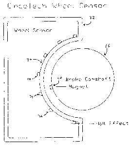
A wheel sensor 32 is mounted adjacent to the brake camshaft and in alignment
with the magnet 30, but not contacting the camshaft 16 so that the brake
camshaft is free
to rotate. In the preferred embodiment the sensor provides an undercut portion
34
complementary to the camshaft so that the camshaft rotates generally within
the sensor.
The sensor comprises a plurality of magnetically actuated detectors 36
disposed around
-4-
CA 02652618 2009-02-05
the portion of the sensor adjacent to the brake camshaft 16 preferably such
that each
detector is generally equidistant from the camshaft.
In the preferred embodiment the detectors may for example comprise Hall
Effect sensors. Generally, Hall Effect sensors measure the proximity of a
magnet to the
sensor by outputting a voltage that depends on the distance between a magnet
and a
sensor but without contacting the magnet. According to the invention,
depending on the
degree of rotation of the camshaft and therefore the location of the magnet
relative to the
sensor, each Hall Effect sensor outputs a different voltage. The voltage from
each sensor
is transmitted to a controller, illustrated in Figure 4. In the preferred
embodiment, the
1o controller uses a microprocessor to calculate, based on the relative
voltages supplied by
the various hall Effect sensors, the approximate location of the magnet in
relation to the
sensor and hence the rotation of the camshaft.
By detennining the angular difference between the rest position of the magnet
30 and the position of the magnet 30 when the brakes are applied (which
changes as the
1s brake shoe linings wear down), the controller can calculate the brake
stroke, i.e. the
amount of movement of the brake shoes before contacting the brake drum.
Referring to Figure 2, the brake stroke length can be calculated using the
length of the slack adjuster, represented by L, and the angle of rotation,
represented by 0,
of the brake camshaft. The length of the slack adjuster is known at the time
of
20 installation of the brake. The angle of rotation is determined by the
controller or
computer on the wheel sensor from the signals supplied by the Hall Effect
sensors. The
following formula can be used to calculate the stroke distance:
2
As mentioned previously, the brake stroke distance of fully applied brakes
25 increases as the brakes wear down. Using the sensor of the invention, the
brake stroke
-5-
CA 02652618 2009-02-05
length can be determined by the controller. The controller can send the brake
stroke
length information to a computer external to the sensor.
Brake pad wear is determined by calculating the current brake rest position
against the brake rest position when the brake shoes were new (which can for
example be
input to the controller, or a calibration can be performed and stored by the
controller at
the time the brake shoes are installed), and when the resting position has
increased by a
predetermined value, the sensor can transmit a `brakes worn' signal to the
external
computer. The signal may for example be sent to an indicator indicating that
the brake
shoes need to be replaced. In the preferred embodiment, the sensor is
connected to a
display in the vehicle driver's compartment that indicates is illuminated when
and which
brakes have worn to the point that the brake shoes should be replaced. In
other
embodiments, the signal may deactivate the vehicle ignition or otherwise
disable the
vehicle.
The controller may be connected to the vehicles brake system, such as the
brake light signals, so the controller can detect when the brakes are applied.
In the preferred embodiment, the controller is integrated with the wheel
sensor. In alternative embodiments, the controller may be centralized in a
central
computer fbr all or some of the wheel sensors or in the vehicles central
computer.
In the preferred embodiment, a temperature sensor 50 is attached to the
vehicle axle 18 close to the wheel bearing. Preferably, the temperature sensor
50 is
attached to the wheel sensor. The preferably continuously, or periodically,
measures the
temperature sensor indicating the temperature of the bearing. The temperature
information is sent from the wheel sensor to the controller. Preferably, the
temperature
sensor is a resistive type device that changes its electrical resistance as
the temperature of
the vehicle axle changes. The wheel sensor converts the electrical resistance
of the
temperature sensor to a temperature that can be communicated to the controller
or central
computer.
-6-
CA 02652618 2009-02-05
The central computer preferably continuously polls the wheel sensors for the
temperature of the axle. If the temperature reaches a predetermined level the
computer
may alert the driver, via a display on the dash, the current temperature of
the specific axle.
Preferably, there are two levels, warning and critical. The warning level
informs the
S driver that the axle temperature is increasing and is an indication of a
potential problem.
The critical level indicates that there is a serious problem with the axle. In
one
embodiment, when the temperature sensor hits a predetermined temperature the
wheel
sensor will send data to the central computer which in turn will warn the
driver that there
are serious problems with the axle.
Various embodiments of the present invention having been thus described in
detail by way of example, it will be apparent to those skilled in the art that
variations and
modifications may be made without departing from the invention. The invention
includes
all such variations and modifications as fall within the scope of the appended
claims.
-7-