Sélection de la langue

Search

Sommaire du brevet 2653501 

Énoncé de désistement de responsabilité concernant l'information provenant de tiers

Une partie des informations de ce site Web a été fournie par des sources externes. Le gouvernement du Canada n'assume aucune responsabilité concernant la précision, l'actualité ou la fiabilité des informations fournies par les sources externes. Les utilisateurs qui désirent employer cette information devraient consulter directement la source des informations. Le contenu fourni par les sources externes n'est pas assujetti aux exigences sur les langues officielles, la protection des renseignements personnels et l'accessibilité.

Disponibilité de l'Abrégé et des Revendications

L'apparition de différences dans le texte et l'image des Revendications et de l'Abrégé dépend du moment auquel le document est publié. Les textes des Revendications et de l'Abrégé sont affichés :

  • lorsque la demande peut être examinée par le public;
  • lorsque le brevet est émis (délivrance).
(12) Demande de brevet: (11) CA 2653501
(54) Titre français: APPAREIL ELECTROMENAGER, EN PARTICULIER CUISINIERE
(54) Titre anglais: HOUSEHOLD APPLIANCE, IN PARTICULAR A KITCHEN RANGE
Statut: Réputée abandonnée et au-delà du délai pour le rétablissement - en attente de la réponse à l’avis de communication rejetée
Données bibliographiques
(51) Classification internationale des brevets (CIB):
  • F24C 07/08 (2006.01)
  • H05B 03/74 (2006.01)
(72) Inventeurs :
  • LEIKAM, JUERGEN (Allemagne)
  • NEUKAMM, ALWIN (Allemagne)
  • HOLZINGER, JOCHEN (Allemagne)
(73) Titulaires :
  • ELECTROLUX HOME PRODUCTS CORPORATION N.V.
(71) Demandeurs :
  • ELECTROLUX HOME PRODUCTS CORPORATION N.V. (Belgique)
(74) Agent: GOWLING WLG (CANADA) LLP
(74) Co-agent:
(45) Délivré:
(86) Date de dépôt PCT: 2007-02-21
(87) Mise à la disponibilité du public: 2007-12-06
Requête d'examen: 2011-03-21
Licence disponible: S.O.
Cédé au domaine public: S.O.
(25) Langue des documents déposés: Anglais

Traité de coopération en matière de brevets (PCT): Oui
(86) Numéro de la demande PCT: PCT/EP2007/001477
(87) Numéro de publication internationale PCT: EP2007001477
(85) Entrée nationale: 2008-11-26

(30) Données de priorité de la demande:
Numéro de la demande Pays / territoire Date
10 2006 024 739.6 (Allemagne) 2006-05-26

Abrégés

Abrégé français

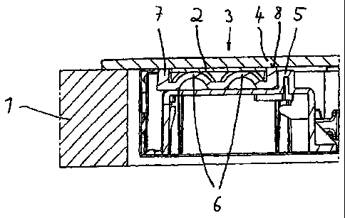
L'invention concerne un appareil (1) ménager, notamment un four , qui présente au moins une platine (2) de commande et/ou d'affichage qui est disposée dans une zone (3) d'accueil prévue à cet effet, la platine (2) de commande et/ou d'affichage en position montée étant poussée fermement contre un autre composant (4) (notamment le côté inférieur d'une plaque de cuisson en vitrocéramique ou d'une zone de commande). Pour garantir une compensation économique et efficace des tolérances et assurer ainsi une bonne compression de la platine de commande et d'affichage contre l'autre composant, il est prévu conformément à l'invention que la platine (2) de commande et/ou d'affichage soit positionnée dans un logement (5) disposé dans la zone (3) d'accueil, le logement (5) présentant un certain nombre d'éléments (6) ressorts qui sont configurés et disposés pour être appliqués sur le côté de la platine (2) de commande et/ou d'affichage à l'opposé de l'autre composant (4).


Abrégé anglais

The invention relates to a domestic appliance (1), in particular a domestic oven, which has at least one operator control and/or display printed circuit board (2) which is arranged in an accommodation region (3) which is provided for it, with the operator control and/or display printed circuit board (2) being pressed firmly against a further component (4) (in particular the lower face of a glass-ceramic hob or an operator control panel) in the mounted state. In order to be able to ensure good tolerance compensation in a cost-effective manner and thus to ensure that the operator control and display printed circuit board is securely pressed against the further component, provision is made, according to the invention, for the operator control and/or display printed circuit board (2) to be positioned in a receptacle (5) which is arranged in the accommodation region (3), with the receptacle (5) having a number of spring elements (6) which are designed and arranged to support the operator control and/or display printed circuit board (2) with that face which is averted from the further component (4).

Revendications

Note : Les revendications sont présentées dans la langue officielle dans laquelle elles ont été soumises.


9
Claims:
1. Household appliance (1), in particular a kitchen range, with at least one
control and/or display
board (2) that is set in an appropriate mounting recess (3), said control
and/or display board (2),
when installed, being tightly pressed against another component (4),
characterized in that
the control and/or display board (2) is positioned in a socket (5) within the
mounting recess (3),
said socket (5) containing a number of spring elements (6) so configured and
arranged as to
press against the control and/or display board (2) on the side facing away
from the said other
component (4).
2. Household appliance as in claim 1, characterized in that the said other
component (4) is a glass
plate or glass-ceramic plate.
3. Household appliance as in claim 1, characterized in that the said other
component (4) is a stove
panel.
4. Household appliance as in one of the claims 1 to 3, characterized in that
the socket (5) and the
multiple spring elements (6) are composed of a single one-piece module.
5. Household appliance as in one of the claims 1 to 3, characterized in that
the socket (5) and the
multiple spring elements (6) consist of two components, of which the spring
elements (6) are
attached to a support (7) that is mounted on or in the socket (5).
6. Household appliance as in one of the claims 1 to 5, characterized in that
the socket (5) and, if
applicable, the support (7) has/have a rectangular outer contour.

10
7. Household appliance as in one of the claims 1 to 6, characterized in that
the spring elements (6)
are produced from a resilient plastic or rubber material.
8. Household appliance as in one of the claims 1 to 7, characterized in that
the spring elements (6)
are constituted of convex protuberances protruding in the direction of the
control and/or display
board (2).
9. Household appliance as in claim 8, characterized in that the spring
elements (6) are of a
hemispherical or spherical-segment shape.
10. Household appliance as in one of the claims 1 to 9, characterized in that
the spring elements (6)
are arrayed in at least two parallel rows.
11. Household appliance as in one of the claims 1 to 10, characterized in that
the socket (5) is
provided, on an inward-pointing rim (8), with a number of centering elements
(9).
12. Household appliance as in claim 11, characterized in that the centering
elements (9) consist of
vertically extending ridges.
13. Household appliance as in one of the claims 1 to 10, characterized in that
the socket (5) is
provided with at least one mandrel-shaped centering element that engages in a
matching
perforation in the control and/or display board (2).
14. Household appliance as in one of the claims 1 to 13, characterized in that
the socket (5) and/or
the support (7) is/are provided with a continuous sealing rim on the side
facing the said other
component (4).

11
15. Household appliance as in one of the claims 1 to 14, characterized in that
the socket (5) is
provided with a minimum of one cut-out (11) in its perimeter.
16. Household appliance as in claim 15, characterized in that the minimum of
one cut-out (11) is
situated in the bottom section of the socket (5).
17. Household appliance as in one of the claims 1 to 16, characterized in that
the spring elements (6)
together with the socket (5) or support (7) are jointly produced in one
injection-molding process.
18. Household appliance as in claim 17, characterized in that the spring
elements (6) and,
respectively, the socket (5) or the support (7) are produced from two
different plastic materials.
19. Household appliance as in claim 17 or 18, characterized in that the spring
elements (6) and/or the
support (7) consist of silicone.

Description

Note : Les descriptions sont présentées dans la langue officielle dans laquelle elles ont été soumises.


CA 02653501 2008-11-26
WO 2007/137637 PCT/EP2007/001477
Description
Household Appliance, in particular a Kitchen Range
The invention relates to a household appliance, in particular a kitchen range
with at least one control
and/or display circuit board that is set in an appropriate mounting recess,
said control and/or display
board, when installed, being tightly pressed against another component.
Household appliances and especially kitchen ranges are equipped with control
and display circuit boards
as needed for displaying information and for entering operating commands. The
control and display
boards are usually set in a corresponding mounting recess. A glass-ceramic
plate or a stove panel is then
overlaid from the top. It is important to make sure that, while in use, the
control and display board is tightly
pressed against the glass-ceramic plate or stove panel to ensure flawless
operation.
In prior art this has been accomplished by inserting compression springs, leaf
springs or retaining frames
with spring elements. The objective in all cases is to press the control and
display board against the
glass-ceramic plate or stove panel by applying spring tension especially in
order to compensate for
tolerances in production and to ensure perfectly flush contact of the control
and display board with or in
the household appliance.
The necessary protection against moisture infiltration is ensured by separate
provisions. Examples
include cross braces provided with an elastic seal. Use has also been made of
cross braces whose
openings are sealed with a silicone glue. Also suitable are plastic enclosures
with glued-on gaskets.

CA 02653501 2008-11-26
2
In one prior-art solution a plastic support is suspended in a metal wall and
the packing is accomplished by
means of a separately glued-on sealing strip.
In another solution, compression springs press the electronics, meaning the
control and display board,
against the bottom surface of the glass-ceramic plate or stove panel in which
case the seal is provided in
the form of a metal cross brace and a sealing profile.
It is also possible to screw the electronics onto a metal support and to
provide the packing by introducing
a silicone glue in the resulting hollow space.
A drawback with these earlier solutions is that in some cases they are
relatively complex, making the
production of the bond cost-intensive. Also, in the case of more significant
production tolerances,
complete compensation for these cannot always be assured. Specifically, a
dependable pressure contact
between the control and display board and the bottom surface of the glass-
ceramic plate or stove panel is
not always guaranteed. As another drawback, some solutions involve the use of
a significant number of
different parts, thus resulting in complex logistics. Moreover, the assembly
process is not always a simple
matter, with a corresponding impact on costs. And in the case of some of the
earlier solutions it has been
found that, over time, moisture can penetrate the area around the control and
display board.
It is therefore the objective of this invention to improve the design of
household appliances of the type
referred to above in a manner whereby the aforementioned drawbacks can be
avoided. In particular,
dependable tolerance compensation during the installation of the control and
display board is to be
ensured. It should also guarantee protection against moisture penetration of
the area around the control
and display board even over the long term. In other words, the control and
display board should always

CA 02653501 2008-11-26
3
securely hug the glass-ceramic plate or stove panel under any production-
related circumstances.
The solution by which the invention achieves this objective is characterized
in that the control and display
board is positioned in a socket within a mounting recess, which socket is
provided with a number of
springs so configured and arranged as to exert pressure on the control and/or
display board on the side
facing away from the other component.
That other component is preferably a glass plate or glass-ceramic plate or
stove panel.
The socket and the spring elements may be designed as a one-piece module or
consist of two
components. In the latter case the spring elements are mounted on a support
which is positioned on or in
the socket.
The socket and, if applicable, the support preferably have a rectangular outer
contour.
The spring elements may consist of a resilient plastic or rubber material.
They may also be in the form of
convex protuberances extending in the direction of the control and/or display
board. In that case a
hemispherical or spherical-segment shape of the spring elements has proved
advantageous. The spring
elements are preferably arranged in at least two rows.
To optimize the circumferential positioning of the control and/or display
board the socket may additionally
be provided with a number of centering elements attached to an inward-pointing
bezel. They may be
constituted of ridges extending in the vertical direction.
As an alternative centering feature, the socket may be provided with at least
one mandrel-shaped
centering pin that engages in a matching hole in the control and/or display
board.

CA 02653501 2008-11-26
4
It will be desirable to provide the socket and/or the support with a
continuous seal along the perimeter
facing the said other component. That seal may consist of a soft, elastic
material such as silicone.
Additionally, the socket may have at least one peripheral cut-out, preferably
in the bottom area of the
socket. That allows cables etc. to be fed through without difficulty.
As a particularly preferred aspect, the spring elements complete with the
socket or support are jointly
produced in one injection-molding process. In that process the spring elements
on the one hand and the
socket or support on the other may be produced from two different plastic
materials. Preferably, the
spring elements and/or the support are made from silicone.
The concept according to the invention makes it possible in all cases to
optimize the compensation for
production tolerances of the individual components so that the control and/or
display board will always
press firmly against the glass-ceramic plate or the stove panel. The proposed
solution thus improves the
quality of the household appliance.
The solution according to the invention can be implemented in a very cost-
effective manner.
Implementing the invention requires but few components, which simplifies the
logistics and reduces the
cost.
Finally, the simplicity of assembly notwithstanding, this approach always
ensures fully functional sealing
of the control and display board.
The attached drawings illustrate a design example of the invention:

CA 02653501 2008-11-26
FIG 1 is a perspective view of part of a household appliance, in particular
the stovetop area of a kitchen
range;
FIG 2 is a section view of the mounting recess for a control and/or display
board;
FIG 3 is a perspective view of the control and/or display board in a socket;
FIG 4 is a perspective view of the socket with a support inserted in it and
with a number of spring
elements;
FIG 5 is a perspective view of the support with a number of spring elements;
and
FIG 6 is an enlarged illustration of the support together with spring
elements.
Figure 1 shows a household appliance 1, i.e. the stovetop area of a kitchen
range. Positioned in a
mounting recess 3 is a control and/or display board 2 that serves to control
certain functions (heating,
timer, operating modes etc.) and, respectively, to display certain
information. Another component 4, not
illustrated in this figure (see FIG 4) consists of a glass-ceramic plate that
is placed on the stovetop from
above. What is important is that the control and/or display board 2 is always
pressed firmly from
underneath against the bottom surface of the glass-ceramic plate to ensure
proper function and to
prevent moisture from entering the area around the control and/or display
board 2.
The structure of the support for the control and/or display board 2 is shown
in some detail in figures 2 to
6. As is most clearly seen in figures 2, 3 and 4, the socket 5, which may be
made from sheet metal, is

CA 02653501 2008-11-26
6
rectangular. It includes a cavity that accepts a support 7 (see FIG 5 and 6),
as illustrated in FIG 4. The
support 7 is a flat component with a number of spring elements 6. As can be
seen most clearly in figures
2 and 6, the spring elements 6 are shaped as spherical caps, with the tops of
the individual spherical
caps serving as support points for the control and/or display board 2 that is
placed on the support 7. FIG
3 shows the board in place.
To properly center the control and/or display board 2 in the socket 5, the
support 7 features in its
peripheral area a number of vertically extending centering elements 9. The top
edge of the lateral rim 8 of
the support 7, protruding upward, forms a continuous sealing rim 10, serving
as a gasket that seals the
control and/or display board 2 from the inside of the socket 5 when the glass-
ceramic plate 4 is in place.
The continuous seal 10 may consist of a soft, elastic material such as
silicone, thus offering a good
sealing effect that prevents moisture from entering.
To permit the feed-through of cables and similar components (including, for
instance, electronic modules),
the bottom section of the socket 5 is provided with a number of cut-outs 11.
The support 7 may be a two-component injection-molded part whose base-support
constituent consists of
a harder plastic than the spring elements 6 which may be made from silicone.
Specifically, to
accommodate the control and/or display board 2, the elastic, thermally stable
component 7 is designed in
a way whereby the bottom configuration is such as to ensure tight contact of
the control and/or display
board 2 with the bottom surface of the glass-ceramic plate 4. The spring
elements 6 will always
compensate for any existing tolerances.

CA 02653501 2008-11-26
7
The other function performed by the support 7 is that of securing and
centering the control and/or display
board 2. The illustration shows vertically extending ridges serving as the
centering elements 9 engaging
the outer edge of the control and/or display board 2. As an example of an
alternative solution (not
illustrated), the centering elements 9 may be in the form of mandrel-shaped
pins that engage in matching
perforations in the control and/or display board 2.
The concept proposed by this invention permits the easy-to-assemble
integration of different
functionalities such as sealing, pressure-mounting against die control surface
(e.g. glass-ceramic plate or
stove panel) and centering of the control and/or display board 2 in the
support 7.
Moreover, given the geometric arrangement of the spring elements 6, it is
possible to variably adjust the
resulting and needed pressures and elasticity values to the specific
requirement at hand.
In particular, to achieve an optimal sealing/pressure ratio, the parts and
especially the support 7 with its
integrated spring elements 6, can be produced by a 2-component injection
molding process.

CA 02653501 2008-11-26
8
List of Reference Numbers
1 household appliance
2 control and/or display board
3 mounting recess
4 other component (glass-ceramic plate)
socket
6 spring elements
7 support
8 rim
9 centering elements
continuous sealing rim
11 cut-outs

Dessin représentatif
Une figure unique qui représente un dessin illustrant l'invention.
États administratifs

2024-08-01 : Dans le cadre de la transition vers les Brevets de nouvelle génération (BNG), la base de données sur les brevets canadiens (BDBC) contient désormais un Historique d'événement plus détaillé, qui reproduit le Journal des événements de notre nouvelle solution interne.

Veuillez noter que les événements débutant par « Inactive : » se réfèrent à des événements qui ne sont plus utilisés dans notre nouvelle solution interne.

Pour une meilleure compréhension de l'état de la demande ou brevet qui figure sur cette page, la rubrique Mise en garde , et les descriptions de Brevet , Historique d'événement , Taxes périodiques et Historique des paiements devraient être consultées.

Historique d'événement

Description Date
Demande non rétablie avant l'échéance 2014-02-21
Le délai pour l'annulation est expiré 2014-02-21
Inactive : Abandon. - Aucune rép dem par.30(2) Règles 2013-06-04
Réputée abandonnée - omission de répondre à un avis sur les taxes pour le maintien en état 2013-02-21
Inactive : Dem. de l'examinateur par.30(2) Règles 2012-12-04
Lettre envoyée 2011-04-08
Requête d'examen reçue 2011-03-21
Toutes les exigences pour l'examen - jugée conforme 2011-03-21
Exigences pour une requête d'examen - jugée conforme 2011-03-21
Lettre envoyée 2009-07-21
Inactive : Transfert individuel 2009-06-01
Inactive : Page couverture publiée 2009-04-02
Inactive : Déclaration des droits/transfert - PCT 2009-03-30
Inactive : Notice - Entrée phase nat. - Pas de RE 2009-03-30
Inactive : CIB en 1re position 2009-03-10
Demande reçue - PCT 2009-03-09
Exigences pour l'entrée dans la phase nationale - jugée conforme 2008-11-26
Demande publiée (accessible au public) 2007-12-06

Historique d'abandonnement

Date d'abandonnement Raison Date de rétablissement
2013-02-21

Taxes périodiques

Le dernier paiement a été reçu le 2012-01-30

Avis : Si le paiement en totalité n'a pas été reçu au plus tard à la date indiquée, une taxe supplémentaire peut être imposée, soit une des taxes suivantes :

  • taxe de rétablissement ;
  • taxe pour paiement en souffrance ; ou
  • taxe additionnelle pour le renversement d'une péremption réputée.

Les taxes sur les brevets sont ajustées au 1er janvier de chaque année. Les montants ci-dessus sont les montants actuels s'ils sont reçus au plus tard le 31 décembre de l'année en cours.
Veuillez vous référer à la page web des taxes sur les brevets de l'OPIC pour voir tous les montants actuels des taxes.

Historique des taxes

Type de taxes Anniversaire Échéance Date payée
Taxe nationale de base - générale 2008-11-26
TM (demande, 2e anniv.) - générale 02 2009-02-23 2009-02-17
Enregistrement d'un document 2009-06-01
TM (demande, 3e anniv.) - générale 03 2010-02-22 2010-01-26
TM (demande, 4e anniv.) - générale 04 2011-02-21 2011-01-31
Requête d'examen - générale 2011-03-21
TM (demande, 5e anniv.) - générale 05 2012-02-21 2012-01-30
Titulaires au dossier

Les titulaires actuels et antérieures au dossier sont affichés en ordre alphabétique.

Titulaires actuels au dossier
ELECTROLUX HOME PRODUCTS CORPORATION N.V.
Titulaires antérieures au dossier
ALWIN NEUKAMM
JOCHEN HOLZINGER
JUERGEN LEIKAM
Les propriétaires antérieurs qui ne figurent pas dans la liste des « Propriétaires au dossier » apparaîtront dans d'autres documents au dossier.
Documents

Pour visionner les fichiers sélectionnés, entrer le code reCAPTCHA :


Pour visualiser une image, cliquer sur un lien dans la colonne description du document (Temporairement non-disponible). Pour télécharger l'image (les images), cliquer l'une ou plusieurs cases à cocher dans la première colonne et ensuite cliquer sur le bouton "Télécharger sélection en format PDF (archive Zip)" ou le bouton "Télécharger sélection (en un fichier PDF fusionné)".

Liste des documents de brevet publiés et non publiés sur la BDBC .

Si vous avez des difficultés à accéder au contenu, veuillez communiquer avec le Centre de services à la clientèle au 1-866-997-1936, ou envoyer un courriel au Centre de service à la clientèle de l'OPIC.

({010=Tous les documents, 020=Au moment du dépôt, 030=Au moment de la mise à la disponibilité du public, 040=À la délivrance, 050=Examen, 060=Correspondance reçue, 070=Divers, 080=Correspondance envoyée, 090=Paiement})


Description du
Document 
Date
(aaaa-mm-jj) 
Nombre de pages   Taille de l'image (Ko) 
Description 2008-11-25 8 219
Revendications 2008-11-25 3 72
Dessins 2008-11-25 3 60
Abrégé 2008-11-25 2 102
Dessin représentatif 2009-04-01 1 12
Revendications 2008-11-26 3 84
Rappel de taxe de maintien due 2009-03-29 1 112
Avis d'entree dans la phase nationale 2009-03-29 1 194
Courtoisie - Certificat d'enregistrement (document(s) connexe(s)) 2009-07-20 1 102
Accusé de réception de la requête d'examen 2011-04-07 1 189
Courtoisie - Lettre d'abandon (taxe de maintien en état) 2013-04-17 1 172
Courtoisie - Lettre d'abandon (R30(2)) 2013-07-29 1 165
PCT 2008-11-25 5 235
Correspondance 2009-03-29 1 26
Taxes 2010-01-25 1 40