Note : Les descriptions sont présentées dans la langue officielle dans laquelle elles ont été soumises.
CA 02658051 2009-01-06
1
DESCRIPTION
POWDER FORGED MEMBER, POWDER MIXTURE FOR POWDER FORGING, METHOD
FOR PRODUCING POWDER FORGED MEMBER, AND FRACTURE SPLIT TYPE
CONNECTING ROD USING THE SAME
TECHNICAL FIELD
[0001]
The present invention relates to a powder forged member
obtainedby subj ecting a powder mixture to preliminary compacting,
then sintering the subjected compacted preform, and thereafter
forging the obtained sintered preform, a powder mixture for
powder forging, a method for producing the powder forged member,
and a fracture split type connecting rod produced using the powder
forged member.
BACKGROUND ART
[0002]
Conventionally, there has been widely carried out a powder
forging method for subjecting a powder mixture to preliminary
compacting, then sintering the subjected compacted preform, and
thereafter forging the obtained sintered preform to produce
machine parts. Examples of typical machine parts produced by
the powder forging method include a connecting rod and a bearing
race. Typically, the component composition of these machine
parts using a pure iron-based powder contains C: 0.45 to 0.65%
CA 02658051 2009-01-06
2
by mass (hereinafter, "% by mass" is merely represented as "%"),
and Cu: 1.5 to 2% from the relationship of machinability and
fatigue strength of products on machining after forging, and
the like. A method for increasing the content of C or a method
for increasing both the contents of C and Cu is generally required
for weight saving or increase of fatigue strength of these machine
parts. Although the fatigue strength of the part is increased
in the methods for increasing the content of C, the hardness
is also increased. This causes a problem that the service life
of a tool on machining after forging is remarkably reduced to
unfortunately increase the product cost. In addition, there
is a disadvantage that the increased content of Cu causes the
generation of cracks on forging easily.
[0003]
A method for adding a reheating process and a cooling
process after a forging process (see Patent Document 1), and
a method for adding other alloy elements such as Ni and Mo (see
Patent Document 2 ) are disclosed as another method for increasing
the fatigue strength of the machine part. However, the former
method causes the increase of processes and the latter method
uses expensive alloys, increasing the cost of the part and
increasing the hardness of the part as in the method for increasing
the content of C. This causes a disadvantage that the
machinability is reduced.
[0004]
CA 02658051 2009-01-06
3
The above conventional methods decrease the toughness of
the part with the increase of the hardness, causing the fracture
surface to tend to become flat. When the part is produced using
a fracture dividing method adopted in the connecting rod or the
like, there is caused a particular problem of easily generating
the positional shift of the part on assembling the part (i.e.,
reducing self-consistency) .
Patent Document 1: Japanese Unexamined Patent Publication
No. 61-117203
Patent Document 2: Japanese Unexamined Patent Publication
No. 60-169501
DISCLOSURE OF THE INVENTION
PROBLEMS TO BE SOLVED BY THE INVENTION
[0005]
It is an object of the present invention to provide a powder
forged member in which fatigue strength is improved while
securing its machinability without increasing its hardness, and
self-consistency after fracture split can be secured, a method
for producing the same, and a fracture split type connecting
rod using the powder forged member.
MEANS FOR SOLVING THE PROBLEMS
[0006]
CA 02658051 2009-01-06
4
In accordance with a first aspect of the present invention,
a powder forged member has excellent machinability and fatigue
strength, the powder forged member obtained by forging a sintered
preform at a high temperature, the sintered preform formed by
subjecting a powder mixture to preliminary compacting and
thereafter sintering the subjected compacted preform, the
sintered preform having a ratio of free Cu of 10% or less upon
the start of the forging, the component composition of the powder
forged member after the forging composed of, C: 0.2 to 0.4% by
mass, Cu: 3 to 5% by mass and Mn: 0.5% by mass or less (excluding
O), and the balance iron with inevitable impurities, and the
powder forged member having a ferrite ratio of 40 to 90%.
[0007]
In the powder forged member, a relative density to
theoretical density is preferably 97% or more.
[0008]
In the powder forged member, it is preferable that a
hardness is HRC 33 or less, and a partial pulsating tensile fatigue
limit is 325 MPa or more.
[0009]
It is preferable that the powder forged member contains
at least one machinability-improving material in a total amount
of 0.05 to 0.6% by mass, the machinability-improving material
selected from the group consisting of MnS, MoS2, B203 and BN.
[0010]
CA 02658051 2009-01-06
In accordance with a second aspect of the present invention,
a fracture split type connecting rod is produced by using the
powder forged member of the first aspect.
[0011]
In accordance with a third aspect of the present invention,
a powder mixture is used as a raw material for the powder forged
member of the first aspect, wherein a component composition
except a lubricant is composed of, C: 0.1 to 0.5% by mass, Cu:
3 to 5% by mass, Mn: 0.4% by mass or less (excluding O), 0: 0.3%
by mass or less and the balance iron with inevitable impurities.
[0012]
It is preferable that the powder mixture for powder forging
is obtained by adding a graphite powder, a copper powder and
a lubricant into an iron-based powder composed of, C: less than
0.05% by mass, 0: 0.3% by mass or less and the balance iron with
inevitable impurities.
[0013]
In accordance with a fourth aspect of the present invention,
a powder mixture is used as a raw material for the powder forged
member of the first aspect, wherein a component composition
except a lubricant contains, C: 0.1 to 0.5% by mass, Cu: 3 to
5% by mass, Mn: 0.4% by mass or less (excluding O), 0: 0.3% by
mass or less, and also at least one machinability-improving
material in a total amount of 0 .05 to 0.6% by mass, and the balance
iron with inevitable impurities, the machinability-improving
CA 02658051 2009-01-06
6
material selected from the group consisting of MnS, MoS2, B203
and BN.
[0014]
It is preferable that the powder mixture for powder forging
is obtained by adding a graphite powder, a copper powder, at
least one machinability-improving material selected from the
group consisting of MnS, MoS2, B203 and BN, and a lubricant into
an iron-based powder composed of, C: less than 0.05% by mass,
0: 0.3% by mass or less and the balance iron with inevitable
impurities.
[0015]
In accordance with a fifth aspect of the present invention,
a method for producing the powder forged member having excellent
machinability and fatigue strength of the first aspect, the
method includes: a compacting and sintering step of subjecting
the powder mixture for powder forging of the third aspect to
preliminary compacting and thereafter sintering the subjected
compacted preform to form a sintered perform; and a forging step
of forging the sintered preform at a high temperature to form
a powder forged member.
[0016]
In accordance with a sixth aspect of the present invention,
a method for producing the powder forged member having excellent
machinability and fatigue strength of the fist aspect includes:
a compacting and sintering step of subjecting the powder mixture
CA 02658051 2013-09-19
7
for powder forging of the fourth aspect to preliminary
compacting and thereafter sintering the subjected compacted
preform to form a sintered preform; and a forging step of
forging the sintered preform at a high temperature to form a
powder forged member.
According to yet a further aspect, the present invention
resides in a powder forged member having excellent
machinability and fatigue strength, the powder forged member
obtained by forging a sintered preform in a heated state, the
sintered preform formed by subjecting a powder mixture to
preliminary compacting and thereafter sintering the subjected
compacted preform, an amount of undissolved Cu in the sintered
perform being less than 10. 6 of the amount of Cu added to an Fe
powder upon the start of the forging, the component composition
of the powder forged member after the forging consisting of, C:
0.2 to 0.4% by mass, Cu: 3 to 5% by mass, Mn: 0.5% by mass or
less (excluding 0), and the balance iron with inevitable
impurities, and the powder forged member having a ferrite ratio
of 40 to 90%.
EFFECT OF THE INVENTION
(0017]
The present invention increases the content of Cu as
compared with that of the conventional one instead of
decreasing the content of C of the powder forged member
contrary to the conventional one, and limits the ratio of free
Cu in the sintered preform upon the start of the forging.
Thereby, since soft ferrite is increased by the reduction of
, -
r CA 02658051 2011-03-18
7a
the content of C to suppress the increase of hardness, the
machinability can be secured and the toughness can be
maintained to ensure self-consistency after fracture split.
Furthermore, since the amount of diffusion of Cu into ferrite
is increased by the increase of the content of Cu and the
limit of the ratio of free Cu to promote solid solution
strengthening, the fatigue strength is also drastically
improved. The cracks of the powder forged member on forging
can be prevented by limiting the ratio of free Cu.
BRIEF DESCRIPTION OF THE DRAWINGS
[0018]
CA 02658051 2009-01-06
8
Fig. 1 (a) is a perspective view showing the shape and size
of a test piece of a powder forged member used for fatigue test
of Example, and Fig. 1 (b) is a sectional view showing a section
taken along line A-A.
Fig. 2 is a sectional view showing an applied state of
a tensile load to a test piece of a powder forged member in fatigue
test.
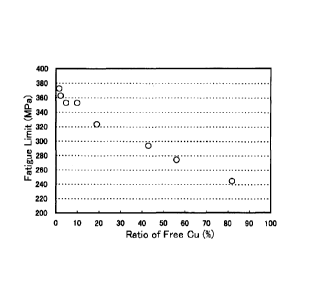
Fig. 3 is a graph showing the relationship between ratio
of free Cu and fatigue limit.
Fig. 4 is a sectional view showing the microstructure of
a powder forged member.
BEST MODE FOR CARRYING OUT THE INVENTION
[0019]
Hereinafter, the present invention will be described in
further details.
[Composition of Powder Forged Member]
First, the reason of limiting the composition of a powder
forged member according to the present invention, that is, a
component composition, structure, density and a ratio of free
Cu in a sintered preform will be described.
[0020]
C: 0.2 to 0.4%
C is an indispensable element for ensuring the strength
of a base steel. Conventionally, the hardness and strength of
CA 02658051 2009-01-06
9
the base steel have been increased by increasing the content
of C to decrease ferrite and increase perlite in the structure
of the base steel. On the contrary, in the present invention,
the content of C is conversely decreased to 0.4% or less in order
to suppress the increase of the hardness of the base steel.
However, since the strength of the base steel cannot be
sufficiently ensured even if the content of Cu is increased when
the content of C is excessively decreased, the content of C is
set to 0.2% or more. Therefore, the content of C is set to 0.2
to 0.4%.
[0021]
Cu: 3 to 5%
Cu is an element which is dissolved in a ferrite phase
in the structure of a base steel on heating for sintering and
forging to form a solid solution to exhibit solid solution
strengthening effect, and is partly precipitated on cooling to
enhance the strength of the base steel. In the conventional
product, Cu is almost used in an amount of about 2% of solid
solution limit in the ferrite phase near the eutectoid
temperature of Fe-C system. On the other hand, the solid solution
limit of Cu in an austenite phase is about 8%. Cu of 3% or more
can be dissolved sufficiently in the base steel to form a solid
solution by increasing a heating temperature as compared with
that of the conventional product and/or extending heating time.
In the present invention, a larger amount of Cu than that of
CA 02658051 2009-01-06
the conventional product is dissolved in the austenite phase
to strengthen the solid solution of the ferrite phase generated
in a cooling process. The content of Cu of less than 3.0% cannot
exhibit the aimed solid solution strengthening effect
sufficiently. On the other hand, the content of Cu exceeding
5.0% causes the free Cu to remain easily. The extension of
heating time such as the extension of sintering time is required
to limit the ratio of free Cu to 10% or less, and consequently
the productivity is reduced. Therefore, the content of Cu is
set to 3 to 5%, and preferably 3 to 4%.
[0022]
Mn: 0.5% or less (excluding 0)
Mn is an element which has the deoxidizing effect of the
base steel and useful to increase hardenability and enhance the
strength of the base steel. However, Mn has a high affinity
to oxygen, and reacts with oxygen in atmosphere in a powder
producing process or in a sintering process of a product subjected
to preliminary compacting to easily produce an oxide. The
content of Mn exceeding 0.5% makes it difficult to reduce a Mn
oxide and remarkably reduce the quality characteristics of the
powder forgedmember such as the reduction of density and strength
caused by the Mn oxide. Therefore, the content of Mn is set
to 0.5% or less (excluding 0) , and preferably 0.4% or less
(excluding 0) .
[0023]
CA 02658051 2009-01-06
'
11
Balance: iron and inevitable impurities
The powder forged member of the present invention may
contain P, S, Si, 0, N and other elements as inevitable impurities .
[0024]
Ratio of free Cu: 10% or less
As described above, Cu nearly two times that of the
conventional product is used to strengthen the solid solution
of the ferrite phase, and non-dissolved Cu (i .e. , free Cu) easily
remains in the base steel. Therefore, forging cracks may be
generated by hot brittleness on forging. In a severe case, the
possibility of the damage of the sintered preform is increased '
on handling between a forming sintering process and a forging
process. Therefore, in the present invention, the ratio of free
Cu in the sintered preform upon the start of the forging is set
to 10% or less. Here, the ratio of free Cu, which means the
ratio of non-dissolved Cu in the base steel, of the total amount
of Cu added, can be quantitated by the following method. That
is, the section of the sintered preform as a member to be measured
is ground by paper and a buff, and is then etched by picric acid.
Three positions having a range of 0.2 mm x 0.3 mm are photographed
by 400 magnifications using an optical microscope, and the total
area of portions of copper color is measured by image processing.
On the other hand, the total area of portions of copper color
of a reference material is measured by the same method. As the
reference material, there is used a product obtained by sintering
CA 02658051 2009-01-06
12
a compactedproduct compacted in the same component compositions,
shape and forming pressure as those of the member to be measured
under the condition of 1000 C for 20 minutes where Cu is not
dissolved substantially in the base steel. The ratio of free
Cu may be calculated using the following formula: Ratio of free
Cu (%) = [total area of portions of Cu color of member to be
measured] / [total area of portions of Cu color of reference
material] x 100.
[0025]
Ferrite ratio: 40 to 90%
When the powder forged member has a ferrite ratio of less
than 40%, the powder forged member has deficient toughness and
insufficient self-consistency after fracture split. On the
other hand, when the powder forged member has a ferrite ratio
exceeding 90%, the powder forged member has excessively high
toughness and large elongation, causing deformation on fracture
split to deteriorate dimensional accuracy. Therefore, the
ferrite ratio of the powder forged member is set to 40 to 90%.
[0026]
Relative density to theoretical density: 97% or more
When the relative density to the theoretical density is
less than 97%, the degree of reduction in the fatigue strength
of the powder forged member becomes large. Therefore, the
relative density to the theoretical density of the powder forged
member is preferably 97% or more. When the relative density
, CA 02658051 2009-01-06
13
is set to 97% or more, the hardness of the powder forged member
becomes HRC 33 or less and the partial pulsating tensile fatigue
limit becomes 325 MPa or more. Therefore, there is provided
a powder forgedmember having securedmachinability and excellent
fatigue strength.
[0027]
Machinability-improving material: Total amount of 0.05 to O. 6%
A machinability-improving material may be added on
preliminary compacting (i.e., to a powder mixture for powder
forging) to improve the machinability of the powder forged member .
As the machinability-improving material, for example, a powder
composed of MnS, MoS2, B203 or BN may be used. They may be used
either singly or in the form of a combination of two or more
members. When the amount of the machinability-improving
material to be added is less than 0.05% in the total amount,
the machinability-improving effect is not sufficiently obtained.
On the other hand, when the amount of the machinability-improving
material to be added exceeds 0.6%, an area occupied by an iron
material is reduced, and nonmetal as the startingpoint of fatigue
cracks is increased, showing a tendency of reduction in the
fatigue strength. Therefore, the total amount of the
machinability-improving material to be added is preferably 0. 05
to 0.6% in the total amount.
[0028]
[Component composition of Powder mixture for Powder Forging]
CA 02658051 2009-01-06
14
Next, the reason of limiting the component composition
of the powder mixture for powder forging (hereinafter, merely
referred to as a "powder mixture") will be described.
[0029]
C: 0.1 to 0.5%
It is necessary to adjust the content of C of the powder
mixture in consideration of the amount of oxygen in the powder
mixture and the kind of atmosphere gas on sintering so that the
content of C of the powder forged member finally obtained is
set to 0.2 to 0.4%. That is, when inactive gas atmosphere such
as N2 gas is used in the sintering process, C is oxidized and
consumed by oxygen in the powder mixture and impurities oxygen
in atmosphere gas. The content of C of the sintered preform
(i.e., the powder forged member) is lower than that of the powder
mixture. Thereby, the content of C of the powder mixture is
adjusted to more than 0.2% and 0.5% or less which is higher than
that of the powder forged member. On the other hand, when
atmosphere gas having high carbon potential such as endothermic
gas is used, carburization caused by atmosphere gas usually
advances to more than the amount of oxidation consumption of
C by oxygen in the powder mixture, and the content of C of the
sintered preform (i.e., the powder forgedmember) becomes higher
than that of the powder mixture. Thereby, the content of C of
the powder mixture is adjusted to 0.1% or more and less than
0.4% which is lower than that of the powder forged member.
CA 02658051 2009-01-06
Therefore, the content of C of the powder mixture may be set
in the range of 0.1 to 0.5% while the change in the content of
C is predicted in accordance with the content of oxygen of the
powder mixture and the kind of sintering atmosphere gas.
[0030]
0: 0.3% or less
The variation of the consumed C amount is also larger when
the content of oxygen of the powder mixture is higher, and it
becomes difficult to set the content of C of the powder forged
member to the target of 0.2 to 0.4%. Thereby, the content of
oxygen of the powder mixture is set to 0.3% or less.
[0031]
Other Components
Cu, Mn and the machinability-improving material are not
consumed and produced on sintering as in C. The content of each
of the components in the powder mixture is defined as the same
as the content of each of the components in the powder forged
member ( although the value of the content of each of the components
is extremely slightly changed by the increase and decrease of
the amount of C on sintering in a precise sense, the value is
within an ignorable range).
[0032]
[Method for Producing Powder Forged Member]
Next, a method for producing the powder forged member
satisfying the above composition will be described.
_
CA 02658051 2009-01-06
16
[0033]
First, the change of the content of C on sintering is
predicted in accordance with the content of oxygen in an
iron-based powder and the kind of sintering atmosphere gas. A
graphite powder in which the content of C of the powder mixture
is in the range of 0.1 to 0.5% so that the content of C after
sintering is set to 0.2 to 0.4%, a copper powder in which the
content of Cu is 3 to 5%, and the machinability-improvingmaterial
of the total amount of 0.05 to 0.6% if necessary are added into
an iron-based powder. A proper amount of a lubricant is further
added thereto to produce a powder mixture. This powder mixture
is subjected to preliminary compacting by a pressure compacting
machine to produce a compacted preform.
[0034]
When the iron-based powder used in producing the powder
mixture is less compressibility, the density of the compacted
preform on preliminary compacting is hardly increased. The
inside of the sintered preform is oxidized during high
temperature conveyance to the forging process after sintering,
and a phenomenon in which the strength of the sintered preform
is reduced by an oxide film occurs even if the sintered preform
is forged. Therefore, in order to soften the iron-based powder
and increase the density of the compacted preform to prevent
the internal oxidation of the compacted preform, the content
of C of the iron-based powder is set to be less than 0.05%,
CA 02658051 2009-01-06
17
preferably 0.04% or less, and more preferably 0.02% or less.
[0035]
Then, this compacted preform is sintered at a high
temperature to produce a sintered preform. Here, referring to
sintering condition, higher temperature and longer time are
preferable because the diffusion of Cu advances and the amount
of free Cu decreases as the temperature is higher or as time
is longer. However, when the content of Cu is, for example,
4%, the ratio of free Cu can be set to 10% or less by sintering
the preform at 1190 C or more for 10 minutes.
[0036]
This sintered preform is immediately forged with a
predetermined forging pressure at a high temperature without
cooling the sintered preform to obtain a powder forged member.
Higher forging pressure is preferable because the density of
the powder forged member becomes higher and the strength is
increased as the forging pressure is higher. However, when a
connecting rod having a shape and size as shown in, for example,
Fig. 1 is formed, the relative density to the theoretical density
can be set to 97% or more by forging the preform with a pressure
of 6.0 ton/cm2 or more, resulting in the powder forged member
having excellent machinability and fatigue strength.
[0037]
Although the example immediately forgingthepreformusing
the temperature after sintering is described in the producing
CA 02658051 2009-01-06
18
method, the preform may be once cooled after being sintered,
and reheated to be forged. In this case, the preform is heated
twice on sintering and forging and the heating time becomes longer
inevitably. Thereby, even when the heating temperature is a
temperature (about 1050 C to about 1120 C) further lower than
the lower limit temperature (1190 C), the ratio of free Cu can
be set to 10% or less.
[0038]
A fracture split type connecting rod produced using this
powder forged member has reduced tool abrasion on machining,
and suppress the increase in cost of parts, and has excellent
fatigue strength and self-consistency on assembling after
fracture split.
Example 1
[0039]
(Influence of Ratio of Free Cu)
A graphite powder and a copper powder were added into a
pure iron-based powder having a component composition shown in
Table 1 so that the contents of C and Cu after being sintered
were respectively 0.3% and 4%. Zinc stearate of 0.75% as a
lubricant was further added thereto, and they were mixed for
30 minutes to produce a powder mixture. The powder mixture was
subjected to preliminary compacting with a compacting surface
pressure of 6 ton/cm2 to produce a compacted preform.
CA 02658051 2009-01-06
19
[Table 1]
Components C Mn P S Si 0
Content (mass %) 0.001 0.19 0.01 0.009 0.01 0.12 0.004
[0040]
This compacted preform was dewaxed at 600 C for 10 minutes
under N2 gas atmosphere, and was then sintered at various
temperatures of 1110 to 1260 C for 10 minutes to produce a
plurality of sintered preforms. The ratio of free Cu of each
of some sintered preforms was measured by using the method
described in the above [Composition of Powder Forged Member] .
The remaining sintered preforms were immediately forged with
a forging pressure of 10 ton/cm2 to produce test pieces of powder
forged members imitating the shape of a connecting rod. Burr
of each of the test pieces was removed, and the surface scale
was removed by shot or the like to provide the test pieces to
a pulsating tensile fatigue test. Fig. 1 shows the shape and
size of each of the test pieces used for the fatigue test. Fig.
2 shows an applied state of a tensile load to each of the test
pieces in the fatigue test.
[0041]
Table 2 and Fig. 3 show measurement and test results. As
is apparent from Table 2 and Fig 3, as the sintering temperature
is higher, the ratio of free Cu decreases and the fatigue limit
increases. When the sintering time is 10 minutes, the ratio
of free Cu is 10% or less at the temperature of 1190 C or more,
CA 02658051 2009-01-06
and the fatigue limit of 325 MPa or more is obtained. Fig. 4
shows comparatively the cross-sectional microstructures of a
referencematerial having a ratio of free Cu of 100%, a comparative
material having the ratio of 15% and an inventive material of
3%. In Fig. 4, portions to which net hatching is applied have
existing free Cu.
[Table 2]
Test Sintering Ratio of Fatigue
pieces temperature free Cu limit Note
No. ( C) (%) (MPa)
101 1110 82 245
102 1140 56 275
103 1170 43 294 Comparative
104 1180 19 324 example
105 1190 9.8 353
106 1200 4.6 353 Inventive
107 1230 2.1 363 example
108 1260 1.4 373
[0042]
In Inventive Example, the ferrite ratio of the powder
forged member was about 70% at any sintering temperature.
Example 2
[0043]
(Influence of Contents of C and Cu)
A graphite powder and a copper powder were added into a
pure iron-based powder having the same component composition
as that of Example 1 shown in Table 1 with the addition amounts
of the graphite powder and copper powder variously changed so
that the content of C and Cu after being forged were respectively
CA 02658051 2009-01-06
'
21
0.1 to 0.6% and 2 to 5% to produce a powder mixture. The powder
mixture was subjected to preliminary compacting in the same
condition as that of Example 1 described above to form a compacted
preform. This compacted preform was dewaxed at 600 C for 10
minutes under N2 gas atmosphere, and was then sintered at 1120 C
for 30 minutes under N2 gas atmosphere to produce sintered
preforms. The sintered preforms were heated at 1050 C for 30
minutes under N2 gas atmosphere, and was then forged with a forging
pressure of 10 ton/cm2 to produce test pieces of powder forged
members imitating the shape of the same connecting rod as that
of Example 1 described above. These test pieces were subjected
to a tensile fatigue test in the same condition as that of Example
1 described above, and the HRC hardness of each of the surfaces
of the test pieces after being machined was measured.
[0044]
Furthermore, the following test was performed in order
to quantify self-consistency after fracture split. That is,
a disk-shaped test piece of a powder forged member having a
diameter of 90 mm x a thickness of 40 mm was produced in the
same condition as in the above description. This was machined
to produce a ring-shaped test piece having an outer diameter
of 80 mm, an inner diameter of 40 mm x a thickness of 20 mm and
having a V notch having a depth of 1 mm and an angle of 45 degrees
on an inner ring diagonal line. This test piece was subjected
to tensile fracture in the depth direction and right-angled
CA 02658051 2009-01-06
22
direction of the notch. Areal area including micro unevenness
of the fracture surface was measured by using an optical
three-dimensional measurement device (produced by
GFMesstechnik Company, type: MicroCAD 3 x 4 ) , and a ratio relative
to a flat project area ignoring the unevenness (referred to as
a "fracture split area ratio") was calculated. Furthermore,
the presence or absence of the shift of the engaged position
of the fracture surface after fracture split was visually
investigated.
[0045]
Table 3 shows test results. The ratio of free Cu of each
of the test pieces before being forged (upon the start of the
forging) exceeded 10% in test piece No. 222 having the content
of Cu exceeding 5%. However, the ratio was 10% or less in the
other test pieces.
_ ,-----
CA 02658051 2009-01-06
,
23
[Table 3]
Chemical , Fracture-
Test Fatigue Ferrite
composition Hardness division
pieces limit ratioSelf-consistency
Note
(mass %) (HRC) area ratio
No. (MPa) (%)
C Cu (-)
201 0.10 2.0 11.7 200 97 1.54 X:deformation
caused
202 0.10 2.5 12.8 209 97 1.53 X:deformation
caused
203 0.10 3.0 14.0 218 97 1.56 X:deformation
caused
204 0.10 3.5 15.2 227 96 1.55 X:deformation
causedComparative
205 0.10 4.0 16.4 236 96 1.54 X:deformation
caused Example
206 0.10 4.5 17.5 245 97 1.52 X:deformation
caused
207 0.10 5.0 18.7 255 98 1.51 X:deformation
caused
208 0.20 2.0 16.2 235 83.6 1.54
X:deformation caused
209 0.20 2.5 17.4 244 84.1 1.53
X:deformation caused
210 0.20 3.0 18.5 307 84.6 1.51 0
211 0.20 3.5 19.7 316 85.1 1.50 0
Inventive
212 0.20 4.0 20.9 325 85.6 1.49 0
Example
213 0.20 4.5 22.1 334 86.1 1.48 0
214 0.20 5.0 23.2 341 86.6 1.46 0
215 0.30 2.0 20.7 270 66.9 1.46 0
Comparative
216 0.30 2.5 21.9 280 67.4 1.45 0
Example
217 0.30 3.0 23.1 340 67.9 1.47 0
218 0.30 3.5 24.3 346 68.4 1.45 0
219 0.30 4.0 25.4 352 68.9 1.44 0
Inventive
Example
220 0.30 4.5 26.6 357 69.4 1.43 0
221 0.30 5.0 27.8 360 69.9 1.42 0
222 0.30 6.0 28.0 306 70.1 Not Not measured
measured Comparative
223 0.40 2.0 25.3 315 50.2 1.44 0
Example
224 0.40 2.5 26.4 360 50.7 1.43 0
225 0.40 3.0 27.6 363 51.2 1.42 0
226 0.40 3.5 28.8 365 51.7 1.41 0
227 0.40 4.0 30.0 366 52.2 1.39 0
Invention
Example
228 0.40 4.5 31.1 367 52.7 1.38 0
229 0.40 5.0 32.3 322 53.2 1.37 0
230 0.50 2.0 29.8 343 33.5 1.40 0
231 0.50 2.5 32.5 347 34 1.37 0
232 0.50 3.0 33.1 349 34.5 1.36 X:shift
caused
233 0.50 3.5 33.3 358 35 1.36 X:shift caused
234 0.50 4.0 34.5 367 35.5 1.35 X:shift
caused
235 0.50 4.5 35.7 376 36 1.34 X:shift caused
236 0.50 5.0 36.8 357 36.5 1.32 X:shift
caused Comparative
237 0.60 2.0 34.3 366 16.8 1.35 X:shift
caused Example
238 0.60 2.5 35.5 375 17.3 1.34 X:shift
caused
239 0.60 3.0 36.7 384 17.8 1.32 X:shift
caused
240 0.60 3.5 37.8 394 18.3 1.31 X:shift
caused
241 0.60 4.0 39.0 403 18.8 1.30 X:shift
caused
242 0.60 4.5 40.2 412 19.3 1.29 X:shift
caused
243 0.60 5.0 41.4 200 19.8 1.28 X:shift
caused
CA 02658051 2009-01-06
24
[0046)
As shown in Table 3, the following is confirmed. Each
of Inventive Examples in which the contents of C and Cu, the
ferrite ratio and the ratio of free Cu were within the range
defined in the present invention, which had hardness of HRC 33
or less, had no problem in machinability. Each of Inventive
Examples had fatigue limit of 300 MPa or more, specifically 325
MPa or more, except some of Inventive Examples (test piece Nos.
210, 211) . Inventive Examples had no shift observed in the
fracture surface after fracture split and had no problem in
self-consistency. Inventive Examples satisfied machinability,
fatigue strength and self-consistency after fracture split
simultaneously.
[0047]
On the other hand, in Comparative Examples in which the
component composition and/or the ferrite ratio fall/falls out
of the range defined in the present invention, Comparative
Examples, which have hardness of HRC 33 or less, have fatigue
limit up to 300 MPa except some Comparative Examples (test piece
Nos. 230, 231) and cause deformation due to elongation in fracture
split to reduce dimensional accuracy (test piece Nos .201 to 209) .
On the other hand, in Comparative Examples having fatigue limit
of 300 MPa or more, the Comparative Examples have hardness
exceeding HRC33 and have deteriorated machinability, and cause
engaged positional shift of the fracture surface to cause a
_
CA 02658051 2009-01-06
problem of self-consistency. Therefore, it turns out that it
is very difficult to obtain the powder forged member
simultaneously satisfying machinability, fatigue strength and
self-consistency after fracture split.
[0048]
As shown in Table 3, the fracture split area ratio can
be used as the index representing self-consistency. When the
fracture split area ratio is less than 1.37, the engaged shift
of the fracture split surface occurs easily. On the other hand,
when the fracture split area ratio exceeds 1.51, it turns out
that the deformation due to elongation becomes remarkable and
the dimensional accuracy is deteriorated.
Example 3
[0049]
(Influence of Relative Density)
Next, there were produced test pieces of powder forged
members having the same component composition (C: 0.3%, Cu: 3.5%)
as that of test piece No.218 of Example 2 in the same condition
as that of Example 2 except that only a forging pressure was
variously changed in the range of 2.5 to 10 ton/ cm2. The
influence of the relative density of the powder forged member
exertedon the fatigue limitwas investigated. While the fatigue
limit was measured, the HRB hardness of each of the test pieces
was also measured. Table 4 shows test results.
CA 02658051 2009-01-06
26
[Table 4]
Test Forging Relative
Hardness Fatigue limit
pieces pressure density
(HRB) (MPa)
No. (ton/cm2) (%)
218 10 99 105.0 346
301 7.5 98 100.0 338
302 9.5 99 101.5 340
303 6.0 97 97.0 329
304 4.0 95 91.5 316
305 3.5 94 86.5 299
306 2.5 93 80.0 286
[0050]
As shown in above Table 4, it is confirmed that the fatigue
limit of 325 MPa or more couldbe ensured when the relative density
to the theoretical density was 97% or more.
Example 4
[0051]
(Influence of Machinability-Improving material)
Next, test pieces of powder forged members having the same
component composition (C: 0.3%, Cu: 3.5%) as that of the test
piece No. 218 of Example 2 as in Example 3 were produced in the
same manner as in Example 2 except that various
machinability-improving materials were added with the addition
amount thereof changed. The influence exerted on machinability
was investigated. Referring to machinability, a thrust force
was measured when a hole was formed from the surface of the test
piece at the number of rotations of 200 rpm and the cutting speed
of 0.12 min/rev using an SKH drill having a diameter of 5 mm.
This was used as the index of machinability. Table 5 shows the
, CA 02658051 2009-01-06
27
measurement results.
[0052]
As is apparent from Table 5, the thrust force is reduced
with the increase of the addition amount of the
machinability-improvingmaterial to improve the machinability.
However, when the addition amount of the machinability-improving
material exceeds 0.6%, the large decrease trend of the fatigue
limit is observed even in any machinability-improving agent.
[Table 5]
Machinability
- improving material
Test pieces Thrust force Hardness Fatigue limit
Amount to be
No. Kinds added (N) (HRC) (MPa)
(mass %)
218 0.0 770 24.3 346
401 0.2 765 24.8 351
402 0.4 755 25.2 350
MnS
403 0.6 750 26.2 335
404 0.8 750 26.5 306
405 0.8 750 25.5 308
MoS2
406 0.6 750 25.8 338
407 0.6 739 24.3 334
B203
408 0.8 744 25.4 299
409 0.6 746 24.9 336
BN
410 0.8 749 26.3 316
Example 5
[0053]
(Influence of Oxygen Content of Powder mixture)
Next, the content of oxygen of a powder mixture was changed
using an iron-based powder having different content of oxygen,
and test pieces of powder forged members were produced in the
same condition as in that of Embodiment 1 described above. The
CA 02658051 2009-01-06
28
contents of C and Cu of the powder mixture after being forged
were respectively set to 0.3% and 4% as the target, and the addition
amount of graphite powder was set to 0.3%+ (content % of oxygen
of iron-based powder - 0.05%) x 3/4 to adjust the content of
C. Referring to this test piece, the content of C and the fatigue
limit were measured, and the influence of the content of oxygen
of the powder mixture exerted thereon was investigated.
[0054]
Table 6 shows test results. As shown in Table 6, when
the content of oxygen of the iron-based powder (i.e., the powder
mixture) was 0.3% or less (test piece Nos . 501 to 503) , the content
of C of the powder forged member was an approximate target content
of C. However, when the content of oxygen of the iron-based
powder (i.e., the powder mixture) exceeded 0.3% (test piece No.
504) , it turned out that the content of C of the powder forged
member was significantly shifted from the target content of C
and fell out of the appropriate range (0.2 to 0.4%) of the content
of C defined in the present invention to drastically reduce the
fatigue strength.
CA 02658051 2009-01-06
29
[Table 6]
Powder forged member
Test Chemical composition of Component
pieces iron-based powder (mass %) composition Fatigue Note
No. (mass %) limit
(MPa)
C Mn P S Si 0 C Cu
501 0.001 0.19 0.01 0.009 0.01 0.012 0.31 4.00 352
502 0.001 0.18 0.01 0.009 0.01 0.020 0.29 4.05 353
Inventive
Example
503 0.001 0.18 0.01 0.009 0.01 0.030 0.30 4.00 351
504 0.001 0.19 0.01 0.009 0.01 0.040 0.15 3.95 267 Comparative
Example
Example 6
[0055]
(Influence of Content of C of Iron-Based Powder)
Next, an iron-based powder having different content of
C was used, and a powder mixture having the same component
composition was produced by adjusting the addition amount of
a graphite powder. Compacted preforms and test pieces of powder
forged members were produced in the same condition as in
Embodiment I described above. The contents of C and Cu after
being forged were respectively set to 0.3% and 4% as the target.
The densities of the compacted preform and powder forged member,
and the fatigue limit of the powder forged member were measured.
[0056]
Table 7 shows test results. As is apparent from Table
7, the decrease trend of the density of the compacted preform
is shown with the increase of the content of C of the iron-based
powder. When the content of C of the iron-based powder is 0.05%
(test piece No. 604) , it turns out that the fatigue strength
is drastically reduced although the density of the powder forged
_
CA 02658051 2009-01-06
1 = 1
member after being forged is almost the same as that of a case
where the content of C is less than 0.05% (test piece No. 601
to 603).
[Table 7]
Compacted Powder forged
Test Component composition of perform member
pieces iron-based powder (mass %)
Density Density Note
Fatigue
No. 3 limit
C Mn P S Si 0 (g/cm3) (g/cm ) (mpa)
601 0.001 0.19 0.01 0.009 0.01 0.12 7.05
7.83 353
Inventive
602 0.005 0.18 0.01 0.008 0.01 0.12 6.90
7.83 352
Example
603 0.02 0.19 0.01 0.009 0.01 0.13 6.60
7.81 335
604 0.05 0.20 0.01 0.009 0.01 0.12 6.30
7.79 279 Comparative
Example