Note : Les descriptions sont présentées dans la langue officielle dans laquelle elles ont été soumises.
CA 02661791 2009-04-07
NUTRIENT-HOLDING AND FLOW CONTROL SYSTEM FOR
T?.T,T Ti\?rn n/1 TTT7'P/~Tr/'1Tl r-~Tmi.S f.,'!Tmr~7~ l: T/~.~.7 mrl 7~T -
nT7mC= r\T~ r~r TTTT?,7~ C`
11V 1J11VL l.lJ11VLL1~11V1V VV1111 YVC]1L1\ L'JJVVV lll 111L71VliJ V1\
LLC31V1L1\J
The benefit of Provisional Application Ser. No.
Tl
~~)'7l'7,j
V/ -t1/-11n7,/ -~, 1 F1 <1eU a T ... t1~J11= ?1 -1 1L7, 2000 Q11U er1L1 'L1
,CU a T~ r rLtiLV1G1\
ASSEMBLY FOR GROWING MULTIPLE PLANTS AND ASSOCIATED
G
TT~n1T/-"/117L71mT1nV1V TT C`vC'mT:'T J1rJ1L1-1n, 1s 1 t 1CC1J~/ .~L....-.L..=
11a1 .. .a_ U1.J,-.,l.1~.llJUte lJ õ1
11C11. 1 m1L_.1C
li\L\
this referenced provisional patent application is
,- .. a 1 >^ . _ ..F ...,- ~ ... _
'1iilVrrVrQLCU 11CrC111 Al1 rCLCL C111~C.
BACKGROUND OF THE INVENTION
l !n
mL. : ; .-, l ~ -. l , . ~ .-. -.-.a .~ ~-, :
1V 1111J 111VC1.. 11+ .1V11 1G1Ql.CJ l/C11G1Q11y LV l,Q1tAC~11111g
accessories and relates, more particularly, to means and
lleLlilJU,.aJ w1L11 ~^ w1ti 11 - 11.11 fciL i-i, =liLer ailU .a ll+llcr
11U1,L1~ 'ei1L+
J care
delivered to a plant for growth and with which the flow
1 ,CtL!.C: ,. Vf WCl , ~.L.Cl to ~J1 ~ ~ ~ ,^ l.i1,.C .~ ,..C1_. ~11L 1J
l.llll L CU .., ~ ~L. _. ,v1,1,. ~
.
During the growth of a plant in a controlled
~ ,~. ~ .. . . !. ~ ~
ei1VLrV111iLei1L, JUL.11 Gls Lil a gieCi111llUJC Vr plailter, waLel ail.:U
plant nutrients are delivered to the plant to keep the
plailt vital aild growiily. Lor t1iiS piirpose, a wcLter llile,
such as a garden hose, can be used to conduct water from a
'~n L, ~- .. ,.- ~ ~ . , .. .. +- ~ ,-, a- 1.,~ , +- .-] ,.- : ~
Lv Jlurle, su111 Q,~ waLC1 1Glul.cL, Lv 1.11C plaill., ai1lA ilul+- .Ll.eilLs
are often delivered manually to an area ot the soil
, ' , ~,~,. ,~,,
[3UJQlerit l.i1C ~llaiil.,.
It would be desirable to provide a means by which
,Qt1L L ~ 1=,_C,.. ~LL,1,1='1GCl Vr oL11 i-L,,_CL .,. nl.lL ,- ...L_ ~lenL~
.,J _ L~Qrl 1J L-. _.C ,.7 ,. UC,1:1vCL.,,CU L .J .ti_.V Ll ~.
~J1L,ll;.
plant as water is also delivered to the plant.
~
L7l.l.VL1A1~_., ~l ~U1,,. .,,, .1.~%, 1 : t 1J Cill V1JJ .~ L-. ~ r.Cl,t lJl
1.11 ..C 1- 1.~.~C prCsc1-..L
1
invention to provide a riew and improved system enablirig
~
rll,Gtlit l1lAl. a-t1 =C11LJ ~ ,... to L. Le ..7 U.~C, '11VC1CtA a 1- L.-.V
L11 1C p1 ,'111t eCll.ll 7_ t1 ' _l.
1Lle l.l L. tCl
water is delivered to the plant so that both water and
11ULr1erlLj are delivered to Li1C plQr1L J11tLU1LdnCo!lsly and so
that the nutrients are delivered relatively evenly over a
a- -. .~ .. ,a -. .a -. ,,, ~ õ-. , .,, +- .,, a- ,. ~ .. 1.. ,. - .. ..7
LQIC~CLCU Girea C1uJQl.C11L a tJlallu lr ~1-a111.J Lv lJC iCU.
Another object of the present invention is to
CA 02661791 2009-04-07
provide such a system which is connectable in-line with the
water supply coiluucted froIC1 a soi.irce aiLu so tLiat iiiitrieilts
are delivered to the plant at a controlled, or metered,
rate.
Still another object is to provide such a system
e11U1J1111g Cl U_C1 l.V 1Lla7LC QUJU-L,ILLCII~.J LV 1.11C fLVW Vl WCIL.Ct l_U
the plant without requiring that such adjustments be made
to Llle VJater f1VW al, t11e 7oUrl.e, JUcll CLs Ql_ Q Wdl_Cf faucel_.
Yet another object of the preserlt invention is to
, fl
LU ,~ JI.Ll1L.1 a _ L. , L. i_ ui1lV , = .U = _ i 1- , . ..- r.
prvviUC ~y.. ~tell wu1111 ~ lLlli~_ateU Lil .7l,iul.l.ULC,
yet effective in operation.
!~iTPiTRTTI[T /ll~ TTT~ TTTTTIPATTT/lTT
JVL"lt'1C1111 UL L11Li 11VVLLVILVLV
This invention resides in a rnatrient-holding and
l Fr. = = l= = L F .C
1LVw cUlltlol s~~Jl1-_e1LL 1V1 cU11ec1.LV11 L11-1'llle VJLI.ll l.i1C 1LUW UL
water for delivery to a plant.
m>.._
L11c systelTL iilciuu~_,_
~ a receptdt/LC 11U'vl1ig an
interior into which nutrients can be positioned and
.,. , .. ._J4.-. ,.. , - _-+- .._ '.~ , L. :. r-. L. -~ a- .~ 111L,lUUL11g a11
111LC1. I.~JVl L 1111,V W1111~11 wC1l.Cr i.J rlerli!1l.l,CU l.V
flow into the interior of the receptacle from a source arid
. _ 1 ., 1- ,,, ,_. L. . _ L_ ; r. L. .-. U . . ~ _.. ~l_.
L.v a11 VUL1Cl. pVit. t +- _111vu J11 W1111.11 watCl alLU iiUl.Lciltj C11C
permitted to exit the interior of the receptacle for
UC11Very ol wCil_er Q11U 11UL_r1eL1t.J 1ro1LL tlle rCl~C~1tCLl.1C l.V l,ic
plant. In addition, a flow controller is associated with
~' i_ _a-. ~', t~ .
Llte receptaLlC LU1 pCrlLLtt111g cl UJer tV dUJU~JL L11C 11Vw
rate of water through the receptacle.
Tl Tl T P T~ T11-' C/'T~ T Tl T T!l TT /1 P T i T - Tl l~ T T.1 T T? (`
(L~LILLl' LL'Jl.l\1C11VLV VL L111'l 1JL~LyVVL1VUJ
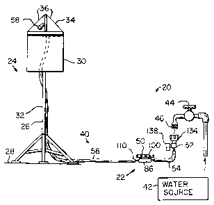
Fig. 1 is a side elevational view illustrati.ng
Jc11C1LLQl.1cQilV U WQl,er Q11U 111.11.11C11L-UG11VC1y Jy~LC1LL fVr
delivery of water and nutrierits to a hanging planter.
n n =, ~ r~ i a a_ r 1- >^
JV L1g. L. 1.~~ Ct V1ew ot sC1Cl.l.Cl( l.olLl.rJollelll.s V1 l_11C
water and nutrient-delivery system of Fig. 1, but drawn to
,__,~,_,_ ,, ,_
a ~liyllt_Ly' .~ctryCr ScULC.
Fig. 3 is a perspective view of the components
~ l 1 4
Lli.i~tratcu lii 1:TP1g '1
. L.
Fig. 4 is a perspective view of the receptacle of
2
CA 02661791 2009-04-07
the components illustrated in Fig. 3, showri exploded.
,,. .. L_ ,., .~
1' l y. J a pCrr,7pel.i l.1 V e V iCw lll 1,11C 11 Vw
controller of the components illustrated in Fig. 3, shown
exploUed.
DETAILED DESCRIPTION OF AN ILLUSTRATIVE EMBODIMENT
m, , ,., + ,~ i- i.. .~ r7 .~ +_ _ ~ , .-. .3
lUliliilg ilow t.U 1.11C Ulawiilgs ili grcal.Cl l.lcl_all allu
considering first Fig. 1, there is illustrated a water and
+- = + .-7 1 = , , = .7 = ..1 7 n - + Y.
iiul_iicill_-uciivery sysl_clTi, geile.Lally 1iluli.Ql_eu Gv, iNiLll
which a nutrient-holding and flow coritrol system, generally
, n .-_ ,-7 ; -_. + .. ..7 11l _,.. L. .. r7 4
,-. ,J 1= ~ ..,. .~ ~ , ; .,. ,
1V ~_11Ull~al-ClA GG, 1.j C1Ll1VVl.L1ClA LIJl UC11Ver1itg W'ater G1111.1
nutrients to a stand-supported planter 24.
.,7
m 1._
111C ~ ~ r.a1.- -.a.,.. ~11U-sUppVlI, ~1`3 _,-1-,. ..7CU r,1-_Q.,_ ~-111,~C_1
,. G7 ~ 111L, ~. ,1. .. ,_1UU.,CrJ . a J1.Q11 .,_U
26 adapted to rest upon a floor 28 or similar underlying
.,_, a '~ n F ., _. 1.-. ., , a ;._ a _..
JL.LUI.tUre d11U a l..oll.alller JV LVL 11ULU1111~ U11t. or -P OI.t lrig
soil and within whicti plants are transplanted for growth.
DrlCfly, tlle stalld 20 1111:11.idCJ a leg absClLlbly d11U a ce11Le1
post 32 which is supported in a substantially vertical
,+ ~w-L ~
or'lelll+.al-1vi1 uy 1,11C 1C1~ aj.~elly, allu' l +_11CLC is ~.JLlJV1uCU a
hanger system 34 including a plurality of cables 36 for
'l n .f, a ; _f. 1- L. (. 7 n G _,. ., .,., L, ,. .f. a ., + + L= õ
Gv suJ~lellulllly l=llc lViltalilel .7v 1LV1u ~ + .11C l.lpper CllU vL 1,11C
center post 32 in an elevated condition above the floor 28.
Ti1C coiltaiiler 3v i~ aii VpCil-I.oLUrJCd l.Vritaliier wll_ii1.11 wiiicil a
plant is transplanted for growth, and any water or
11ULr1e11Ls adUCd to Lhe 1.llterlor of tlle coLltcl'lL1Cr 30 to
promote plarit growth therein is typically added to the
~ - 3u n + v . ,. ~ t.. + ..,.. 1.1.. .. ~ _. +
1o11La111e1 V LL11Vl.11~ ._. 11 l-i1C opCll l.Vrl l_1CLCVL.
It wiil be uriderstood that the depicted planter
'~ ~ _ = 1- r, r a =,.7 r. - , F , c l 1- ._ .., r.
L.`3 lj 111~.C11UCU ~-U prVVlUC Gi11 Cli'ClLLp1e V1 Cl l~1GtJS Ul ~JlaL1l,CLJ
with which the nutrient-holding and flow control system in
JV al.corUarice wil_11 l.lle preJerlt 111VGrll.lon can be uL111GGU. 111C
planter 24 can, for example, take the form of a vertical
L.. -1.-. ., .,_ ._. ; - L, r. ._ t _ ... +
L1d11y111y yrow 1Jay,... Vr a collultVil lldlly111y,-.. udJ1LCL.
CAI.I,Utulllyly,
the principles of the present invention can be variously
~
aL N=iCU.
The water and nutrient-delivery system 20
CA 02661791 2009-04-07
includes a network, indicated 40, of conduits, described
~ ~ , ~ ~A ~.. ..m
ltcleiil LvL uc=lvcry vL wa~LCL -L_V Lllc iJldntcr L=7 LLVILL a
source 42. In the depicted system 20, the source 42 ot
WQtC1 '1J alC-CjJ11J! e t11rVUg11 Q wCltCr la'tl'l.Cl, 'i'3 liQV1111~ C!L
externally-threaded spout 46. In addition, the system 22
1n1,11UUCJ U r1U1.11.C11t-11V1U1111~ 1Cl,epl_UL,LC, or rCIC~/l.Ul~1C
means, 50 and associated flow controller, or flow control
1-L-LCd11s , 5L. 111 l._11e deplcted systelll 20, tile receptdl,le LlLealls
50 and the flow control means 52 are connected in flow
'7 !1 ' i- ; L. . . ..7 , , ; L, r. ' C A L, . . a- L.
1V c~o1LL1LLU111t~a1.1V11 1J~/ Q l~J11UUll.., Vl 11Vje, ~JVlI_ll~ll UUl_ 1.11e
two items 50 and 52 can be directly coupled together iri
al.l,orUalll,e Wll.ll t11e b1oCLder Ctspel.t.s Vl t11C presCrlt
invention.
m_. a._ = ~~ ~
111e L.Vr1UUlt 11etWVrili. ` n3nV V1r l_11C UCp1l.tCU JyJI_e1LL GV
includes the conduit portion 54 (introduced earlier) and a
co11dU1t porl.1o11 56 W111c11 extellds JJeI_WCell 1.11C 11U1_r1e11t-
holdirig assembly 50 the top of the container 30. The
!. ,.. J~ !. .J . , ~ ~ C A ' . l . . .J r, ~.
UCLJ1ll_CU,a cV11UU11_ pVrl+- _1V11 J`7 1111~1UUC~ d vertll_,a11y-U1JplJ~JeU
section which extends upwardly along the center post 32 of
a ~ ~ ~- ' ~ , l ,a = .~
G.V l_Lle s1.a11U L.V d11U.~ aiLVl_1>^1G1, ot 11V1'1GVL1LU11y-U1.7rlVjCU,
.7Cl.l_1_V11
which extends along the floor 28. Therefore, water which
1,. F L.
._l~ G_1.. _. _...V1LL G-.d..U~l~. r,C n n C 1
V~I V1 11C 1_V11t.a111
1s l.Vr1UaUtCla .1 1 tL. 11C 1L `i`i =o 1.11e L 1.
30 travels in sequence through the flow control means 52,
t11e cVllla.lult pol.l_'loll 54, tlte recCpt_dl,le 1llCdlls .CiV d11U l_11C
conduit portiori 56. Upon exiting the exit end, indicated
C O '- -- ir. ~ ,.7 . . , J- J- ' C r L, , l-. .~ C O = ;t_u.!- .~
J_~ , V t L_ 1 1 C l V 1 L U U.L l_ p V r l_ 1 V 1 1 J V - W 1 1 1 l 1 1 e 1 1
U J V J_ s s l a l_ eU
above the top of the container 30, the water is permitted
t0 yiavltatl0ilaiiy ii0n ui wilward.liy 1i1t0 ti1C cGlltalllcr 3v
where it is exposed to a plant (or plants) growing therein.
'] !l = l. __ ,. rl ~ '^~ '
JV VY1L11 1C1L-C1C111.C l..V L1l~J. L-`3, 1..1L.1C 11U1,11C11t-11o11.A1111
receptacle means 50 is somewhat jar-shaped in form and
dcfines ail iilter-Lor 82 adapted to iloid an alilount oi
nutrients (such as a fertilizer tablet 84 illustrated in
r+ ; n 1 ~ -- ' _ _ _ i Y. i _ _ -.1 - 1 .i l-. -,. ~ , , ,..- L-. .i L. ..
Llg. `3) Lll1 liLiLiiilg N%ii.ll wal_Ci l.Lirel~telA 1-111VUy11 l_11C
receptacle means 50 on its way to the container 30 of the
i
CA 02661791 2009-04-07
planter 24. To tYiis end, the receptacle means 50 incl.udes
~~ _ L ~ ~: .~
an Gioeil tGpNeu Collpar tiieil t ~~v lia`'iily a plailai uiJL Olii ~ (j_ anU
cylindrical sidewails 90 and further includes a removable
"I r1 n 1"l _. F -.
E ..., __ .~
l~Qrl 1VV. LC1111CU Q1VLlg LLLC s-UeWQ11J 7V V1 L11C I.VLLLpC11L1ltC1LL
86 and adjacent the top thereof are external threads 92
-t.;
w1L1.1,11 L,oopeldl.e W1~.11 L11C l~alU 1VV ~.V ~1e1111'Lt ~.11C L:Ctp 1V'J
1_V
be threadably secured about the compartment 86 and thereby
~:- ~
vvcr Y i_l-lc vpeil tvt/ ~Licrevi.
Furthermore, the receptacle means 50 includes
in
,. , . õ_a ; ~ _ ~ _ .a .
1V pllrL 1LLea11s, gerlerall~% 111ULl..QLCU 1VG, W1111.i1 aclolLLLLLVUGLI.C
L11C
attachment of a corresponding conduit portion 54 or 56 to
~v ~V ~ ~ ~ ._ ~L ~ L,_11~C
l_lll- leleptUL.1C t1eQ11J .J a11U l.V t11e1CUV ~1erLLLL i1VW Vl
water therethrough. More specifically, the port mearis 102
~ -. = n a ' .a _ = a ._ ~
1111.LUUCJ C111 1111CL ~1Vrt 1V'3 UlspVSeU V11 Vlle JLUC Vl tlle
compartment 86 which permits the attachment of the exit
~. -] ..., a ; ,_. _ ,_1 ? l /- _, ,., a . _ ; C n i 1._ _
C11U, 111U11~dLCU 1VV, V1 t11C cV11UUlt poLL1V11 J`3 LlJ L11C
receptacle means 50. In the depicted receptacle means 50,
r. , ,._ J- .., ~ , /l A ._ .d ~ ,_
1.11C 11_.. 11CL pVL~. 1V`3 1.~ s1GCU l,V lJe rel- elVCU Uy l.L1C e111t e11U
106 when the exit end 106 is directed endwise over the
=~ n .f. , _. ' n n c ;
LL.' 1111C1. pV1L 1V`3 tV Ci s1Ll.ll~-L1~L1.lll rC1aL1V11J111p L!LClCUUVUI..
The port means 102 also includes an outlet port
. a_ c- c~ ~ t-
Liiv uisposeU on tlle siuc oi tile ColTipartlTieilt o0 opposlte tlle
inlet port 104 which permits the attachment of the inlet
_ I = a 1 _ -I "I n t ~ L. _ I . . = = ~ /'
e111A, 11LUlcatel.l 11 V, o- l.tle 1~o11lAUl L pot t.LOli -l V Lo tile
receptacle means 50. In the depicted receptacle means 50,
+- L. ,_ . _ ~ _.- ~ '1 il o .~ .~ ., L-. _. ,a L. . , 1 1-1 - ... i , -
1,11C VULJ_Cl, pVLL 1VV 10 s1G r, CU LU UC rel,el 'V'r. CU Uy L11C 1111C1.
end 110 as the inlet end 110 is directed endwise onto the
_ nn ~
i~LiLiCt pori_ 1VU Lv
If desired, the compartment 86 and the inlet and outlet
3V rlorts 1V`3 Gllllai ~1VU cQll ue 1lLolLtCd ClJ Q U111LCiry JLLULl.U1e VUI,
of a relatively hard plastic material. Furthermore, each
_'~_ _,, _ ~,_ ,'~' ,n'_
Vl t_1,~1C 1111CL U11U oL1L1Ct po1~.7 1V`3 a11U 1V0 1s prClCraU1~/
provided witt: a barbed outer surface, as showri iri Figs. 3
a1 'A, L'V _. e1111 1.11 ,.,L.-.Q_=-.11.-.L,r.C +hrC . se õ_ ~l. L-. LJ.~C~I,.
. ,-.WC,-.C...lt + L1L.1C .. pV1-..- 'L a11 .._U ~ .~ ,-.
.,. 1U .-7,l~llreiLell -1- .1L.C
1
conduit portion connected to the port.
CA 02661791 2009-04-07
The removable cap 100 of the receptacle means 50
iiicludes a plcteil cGvcr p`vitloil iiv aild Cyllildii ai
sidewalis 118 which extend downwardly (as viewed in Fig. 4)
11_1Jllt t11C IVVCr pVil.lVi1 1LV. 111C litLC11V1 JULlQI,C:J Vl L1!C
sidewalls 118 are provided with internal threads which
IJVVpCtCiLC W1L11 L11C C1SL.elllal L111CQUJ 7G 1Llg. 4) V1 L:1C
compartment 86 so that the cap 100 can be threadably
l. ..1 + ..., r. .,. o ~ L. . I - ' + L. , n n
attalllcu Lv LLic l~llilparLltlCUL vV Aly JLl.Cwiiiy Lllc l~aiJ 1Vv
about the compartment 86 (to thereby close the open top of
1f + + Or >^..
1v ule l.V1iL~laLUUC1IL uv~ vli l.clitvvel.l L1Vlu L11C collparL1t1C11L Vv uy
uriscrewing the cap from the compartment 86 (to thereby
rIrVVLdC al.l~e~Js to t1l1e L11LerLVl V2 Vr t11C rCl,eJl.Qc1e LLLCQlls
50). As is the case with the compartment 86, the cap 100
1.a11 a1slJ lJe forlLLed, or mtoldCd, ol,it Vf plas 1.1c 1LLa te11Ql ; C1111A
if desired, the exterior surface of the cap sidewalls 118
1-- = .~] ~ .~ L_ = , , _ l ; L. , n A
Cail ue piG`v1uCU Wit11 arilaiiy eritelulilg piGt uerailCe~ 1~
which are regularly spaced around the cap 100 to increase
i l-. õ =~ v. L, ; L. + L. ~ , n n L_...
= õ1
Lllc eaJC wiLll wlllc,ll L11C cClp 1vv cail 1JC glippe\,1.
To ensure a tight seal between the surfaces of
In + 1., '1 n n a Li o c
G V L.iie l~ap 1 V V a11U tle l.VlLtpar t1LLeL1L O V, t11C 1Cl~C~JI.Ql1C
LlleQll.^7 JV
preferably includes a flat washer 122 constructed, for
CficYlllrJlC, Vl C1aJtV1ltC11c 1LtC1Le1'1G11 W 111.11 1J ~IVJ'1t1V11CXUlC
along the edge of the compartment top so that when the
r C - C l u L. l l e l~Qp , n (l ' - ~ 4 yY. ........ 7 L. . , . + + L. - O c
lil v V ivv i 1,111LC11ClA a1JVUL Lllc c.VfiipGarLlLlClll. vv,
the washer 122 is tightly sandwiched between the top of the
...õ ~-. + () /_' ,J + L. r. ,J ~ ... ~. , ..1 r. L J- L. r. ~ = , , /_'
LVLLpCirLlllCilL CJV Q11U 1.11C U11UC1J1UC V1 L11C cVVCr PVrL1V11 11V.
It follows that the removable cap 100 provides a
Usel Wltl! al.l.e.Jj l.V t.lle ltll.el;VL VL. Vl tlLe lel.ejJtalle 1LleailJ
50. For use of the system 22 (and while the flow of water
JV 1.11ro11g11 t11e receptdl.le 1LtearllJ JV 1s slll.lt off) t11e L,CirJ 100
is removed from the compartmerit 86 and then fertilizer or
other plant nUtrlCllts (W1111,11 1Ltay l.~Je 111 JVl'1d Vr 111-Ji11U fVr1LL
arid, in either event, is water soluable) is placed within
+ L, = +- = f~ ~ 1õ .. 1- -.Ci~.J_ , m .. , n ~ =
L11G' L11LCr1Vl UL. Vi1 L11C 1ele~lLe 1L1Calls C ='~J~V. 11-.11C lap 1VV lj
then replaced upon the compartment 84 to cover, and thereby
6
CA 02661791 2009-04-07
close, the top thereof, and the water flow through the
ici;e~it<zcie lLieaiis 50 i:~ turiied viv. t-T-ia 'wate,i i:~ i0.itcu 1i1t0
the receptacle means 50 (i.e. through the inlet port 104
F) / L. _. .] ~
t11C1CO~. , L11C 11uLr-Clltj 1L11A w'ltll kC.l~. 1Je1~V1Le:? er1t1.C1'111eU Vv
or dissolve within) the water flow so that water which
Ju1JJCqLLC11L.1_1% C1S1ts l.,lle rCcCpL.CYc1C 1lLCQ11s JV LL1rVUgi1 L11C
outlet port 108 carries with it the entrained or dissolved
1er 1.1i1Ger toward l,lle p1a11tCr 1,o11tcl1rlCl 3V .
As mentioned above, there is associated with the
~
LV 11ut11e11L-11VldLtll~ recCpl,Ql.le 1LtCC111s JV f_LoW colltrol meQ11J,
generally indicated 52, for controlling the flow of water
~ L. C!1 .-. 1. = = a
L11rVl.lg!1 ~.lL.. le rCl~epJ-Lal.,le 1LLCQ1IJ JV. 111 L1110 l~ot1!1CcL1ol1
aL1U
with reference to Figs. 3 and 5, the flow control means 52
1riCil.lueJ ci paJSagewQy-defiii_i.iiy body i32 licavlily Ci LGilileCtOi
portion 134 which is adapted to be threadably connected to
,~ >^ a_ a n c ,,. - n n
tl,--le Cditelllally-t11rCClUCU jpoUt `3'V o1 l_ile WaLeL 1d',1cCL 44,
and there is mounted within the body 132 a flow control
'D r_ ti,. _; i_ ~o U; 1-1
vCl_LVC 1JV llaVllll~ ail al.AJu.~LlltCilL n11lJAJ iJV wlllc.ll perlLlits Cl
user to adjust the rate of flow of the water flowing
'l ,r1 +- ,~ _._ r. . , ,.. t, a- t., .. .~ = , t 1- 7 n 7 L_ _ , ~ -, ti t ~.
.,, i~ r. 1 _.r. r. tr. 'I '~ n
L.V L111VU1J111 L11C 1,V11UULl, GVG Uy 1VLQl_111y 1.11C 1111V1J 1.JG 1C
,LQt1VG
to the body 132 to alternative positions. Each component
Vl t11C 11oW 1~o11trV1 llleanj JG l,all UC 1LLOIUCU, VL 1V11ltCU, Qs Q
separately-identifiable component; and if desired, the
CXter1o1 JL111ace Vl t le c11111!ector port1o11 134 l,<111 be
provided with axially-extending protuberances which are
l l - , .~] +- 4... _ ' ~- . , t L. ..
regll-ar.Ly jpaleU 1.11CLCCL1vu111A L.U 1.ILl.prVVG LllC lQpaliLy V1 L11C
connector portion 134 to be gripped by a user.
m L. _. ~ , .. -
,,. .. , -. , _ , 7 /" .~ -F ~ L. ~ õ1 .~ .: _, t- ., ,~ .F , !.
111C .L1VW 1~V1!LlV1 VC11Ve l,JU VL 1.11C UCCILI~LCU -=VW
control means 130 is a ball-type, infinitely-variable valve
. . = = = L = l_ 1 _ .
Jv w1lVJe rlVJ1l.1V11 W_i_t111.1i l~..lle 1JVUV L..JG Vl l.lle 1~VW 1.V11~LO1
means 130 can be adjusted between a fully ON orientation
(ds 1J 11lUsLrCItCU 111 DVllU 1111CJ 111 L1g. J) a11U d 11.111V
OFF positiori (as is illustrated in phantom in Fig. 5) so as
LV ._ ' ..i .. all .~ .. -J, ;IICU l ..1 lVw a- .. L. .. a- _W... .-. ,.,II '1
tU , . l (lTT
p1VVlUC y UC F1 ral.C 1JCLCC 1L.1C l.Ly IJLV
corldition or fully OFF corldition (for providing a flow rate
CA 02661791 2009-04-07
of zero through the valve 136). For example, if it is
,-.7 = 1 1CU -~ ~ L~ ', L i i _ 13 c L, _ 6
UC
1.11a~, i_lle loow ral.e tl_rV~.lg1 1.Ir.11e Va 1Ve V 1Je Ci1JVU=
midway between ttle tully ON and fully OFF conditions, the
I,L1VU 13U J11o%jId be LIIoVCd re1C1t1VC Lo the VQ1VC 1.316) l.o C1
rotational position which is about half-way betweer; its
. . r'+ i-` = ' L. _. .J !-
1U11y lJ1V c1111.1 1U11~/ llr'L pUJ1L1Vli~~. 1, 1,c111 UC 11ULCU L11UL L11C
knob 138 is rotated relative to the body 132 through only
about 111rlety lACgrees ol al!gU1.ar LlloVelLLent as lt 1J Lotcltel,l
between its fully ON and fully OFF positions. Thus, if it
L U = i s u ~ i , õ ~ ~
es lrcQ to pcrlillt a reiaLvcl y siliaGr ur ;Lp, iatc oi
fluid flow through the valve 136, the knob 138 would be
1_ ~ a , +. = _~ ~ , _ , , ~ ~ ~ = ~ =
ro La LCU 1e1a L'l V C LU t11C V U 1 V e UUI.AV 1JL l.U U PUJL L Loll
disposed relatively close to, but riot in, the fullv OFF
PoJitlVil.
For corlnection of the body 132 of the flow
1.o11tro! 1LLea11s 13V to l.ile 1,o11dU1t port1o11 54 ol tlle co11l.LU1t
network 40, ttle body 132 includes an exit port 140 which is
. _ r . ~ .~ >r. ~ ~ , , ,
lAlspVscLA l.lUwll~tlealil v1 the 11Vw cVilt.rul valve 1JV ai1U 11-1
flow commuriication with the connector portion 134. In the
,_ ... = i. a ~C ~ ~ '1 n n = ' .a
~.U UC~l1cLeU 11oW l~olltrol 1LeCl11s 13V, t1L.1C CIi1L porL 1`3U 1J 0 1GCU
to be received by the inlet end, indicated 142, of the
corlU .,7 .ll't pol
l .Ll''Ull J~ C~ w '111 ,Ct CnU .~ -1 1A'3G'l l 's U ._] 'lrectC,
11C11 t.1L.1C 1 U
endwise over the exit port 140 to a snug-titting
1C1ae'1U1151!1p t11C1CC1bVUL. 27s .LJ 1.11C CC1sC W_Lll L11C 1111CL Ci1111
outlet ports 104 and 108 of the receptacle means 50, the
ciilt pOrt i4v is preieral.il`y' prGvidcu wltil a.'`~icirl1"~cd ou~cr
surface to enhance the securement between the port 140 and
_. ' . .~.1 "I A '~ '7-. ,~ `.7 , , ; ~ ~
L11C L111Ct CLLU 1'7L. ol LLLC 1,V11UU1 L pol L1o11 J'Y .
Exemplary dimensions of various components of the
7n ~ ~,n =._t~ ~ t-.,__.._ r_, x. a; ~
~V s~/sLClll ~IJ arC prUV1UC'l1 1fCLC CL.S 1U11oWJ. 111C o. ~1LCL 1,11a1LlCLC1
of the removable cap 100 of the receptacle means 50 can be
0 C r. L, ._ r. . ~L.,~ ,.7., ,-. +- ,~ L. õ
alJOl'At ~.. L`~J iill.lLC.'~, Lllc UcrlL1L.1 Ul L11c cap 1vU ~ail uc auvUL
1.2 inches; the wall thickness of the cap 100 can be about
!l !l `7 1 ' . L, r. . L. ,~ +- ,-. -.. ,~ 4 F + L. !. +-........ J- 86
L
V. V/ V 111~,11CJ, L11C VuLCr lA_LC11lleLer lt LL1C l~VlllparLlllC11L uu V1
the receptacle means 50 can be about 2.125 incties; the
8
CA 02661791 2009-04-07
depth of the compartment 86 can be about 1.1 iriches; each
L~ ,-. C A
lJl L11C l,V!11.1U1L ~JIJLILVllj J13 at1V JV 1-C111 1JC p1.llV1llCl,l IJy a
plastic hose having an outer diameter of 0.5 inches; and
riu9 A`l nv i_ W_ J. t , L-. r. c L~ 1J _. a r L,u c ~. .J u
'J. v/, q ,[l 4 =:a _ = 1_
th e p lJ l. t s C,, 1.v ~i1 t ll L.vitiiec l.VrJ
associated therewith) are sized to be snugly accepted by
C
l.lle l~lJlll.tU1 L rJV1t1V11J 11aV11i'~ ~. 11C V.J 'Lllcll oULC'1 U1a1LteLC1
It follows from the foreqoing that a water and
lil.ll,rleill,-11e11Ve1V Jy~LC1Lt GV 11a_ Ueell UesL,11UeU W1-~1 w1111.11
water and nutrients can be delivered to a planter 24.
, , 1.. = 4 _ , _ .J = ~ L. = 1- L. } '? !l
1V 1'Ur ~.11er1LLllLG, Lllele 1s i11LlJ1pVrateU Wltlllll Llie .?yJLC1Lt Gu a
nutrient-holdinq and flow control system 22 including a
~
Lcl~epl.al~-e liteaZls Jv 111LO w111c11 a l.Ijer l,aLl uC1uVj'1L
fertilizer or other plant nutrients for delivery to the
, ', d J-~ ~~_... ~ , ..7, ',
plantCr L.`3 V%iLll watel L FLV1L1 a JVUrcC `t~7 anu,.d '1ill.luulilg a L1Vw
i5 control means 52 through which the user can control the
rCLLC lJl fiVW ol WcXLCt L11L1>UIJJlt t 1C recCpLQc1C LLLCa11J 50.
Thus, the receptacle means 50 and flow control means 82
. , = L.
prG tc.. .~ -. a i,0ilveilieilL +- anu (7 uiCO , =lca- +,L.. .]CU ,uy
`v'iu~ 1TLpL litcails wi11C11
water and fertilizer or other nutrients can be aelivered
L, n F 1- L-. l ~ /7 k.
LV a11LlUlLaltClJUj_i-~% LV L11C l.lJ111,C11i1eL JV V1 Ltle j.~lLaliLel G'Y QL
Cl
metered rate and allows a user to control the flow rate of
watLcr Lll i_ L.rvugu i_11l, i_ L.c.. C(, ai] 'n-G Ih-
recepLaCic litcails ~v lu i~ Luc
container 30 without having to control the water flow at
~ >^ ,.. - - n
Lllc ia'u'c cL 4 -z.
25 It is envisioned that the aforedescribed system
'~ 1, = = , , _ _ , , =a-_.,~ 1=õ .., de, = . 11
lU
pQri_ii~iiLarly well- _ ~i.iCU LvL llvCr'1ili~ 11l.ju ~
fertiiizer (which is poured i_nto the receptacle means 50)
-~v n _ , = i ~
e l,lJiit-a_LitC[r J at Gl re.!ai_'1ve1y J1Vw rC1tC, aitu ~J1iVVilAC'~
a user with an alternative to known, more-costly greenhouse
n t_ _..;.._ _. f- _ _ ~ ; __. ,.. a _.. ; ._. _. L. _ _.. ~ _ v. _ __ _ _ . ,
_.
JV WQl.Ct111'~ cXlll_.~ L LCCU1111~ UtlrJ .~yJLelftJ. 111 1J~.11C1 WlJ1U~,
IJCI~QU:~C
the system 20 need not involve the relatively sophisticated
eqUIP1tle11t l.olLtiLLOr11y assol.laLed w1t11 gree1111oUse waLe1.111g d11U
feedirig drip systems, such as can involve timers, nutrient
- ~ ~
1 I L I. V 1 J
~1 a 1 r e 1 J, w a-L C l 1 11 1e J Q i 1lA p U 1 L t p s, L1 1C J y J L Cm
35 advantageous in this respect. Furthermore, the system 20
~
CA 02661791 2009-04-07
is relatively easy to use in that tertilizer_ can be
a a ~ >-
UCrJIJ.~: _C\.1 Vl pvl.lrCl1 YV1 t-iL.L11 r ~11e LC:1.eltac1C lileail~~ W
iti,11ii G
few seconds, uses water pressure to deliver the nutrients
U.L1G'.J:~`' ~_l'J l.L1C p~dnt, q11U VCI,Gt~AJI. l,!1C L1U~_ilCltl.~ _r1LC
~ delivered to a targeted are:: ;by way of the conduit portion
J V/, 1C'.AUI_,r:J liiuL r lellL Wci s tC.
It will be understood that nurnerous modifications
<YnU ,JuJ.:stlti.lttoils can Ue had tlJ tlie aloredejl,rlUeU
embodiment 22 without departing from the spirit of the
T - .=.7, ,., . ;. L. `. ~- _~- ~ 4 ~- ~ M~ ~ ~, ~ ^!,
1iJ 1r1~/e111__LV11.. f]Ll~olU111l~ty, l_11C ~1ULCUC~l~.L11JCU
e1L~/JV1111tLCLlt LL.
is intended ior the purpose of illustration and not as
14
11 L L 1 L Q:. 1 V 1 1.
lo