Note : Les descriptions sont présentées dans la langue officielle dans laquelle elles ont été soumises.
CA 02666399 2009-04-09
WO 2008/044218 PCT/IB2007/054158
MICROWAVE TREATMENT OF BULK PARTICULATE MATERIAL
THIS INVENTION relates to the microwave treatment of bulk particulate
material, in particular bulk multi-phase composite material. Specifically, the
invention
relates to a method of treating bulk particulate material with microwaves and
to bulk
particulate material microwave treatment apparatus.
The use of microwaves to treat bulk particulate material, such as ores, is
known. The Applicant is aware of a material handling system as disclosed in
W02006030327 in which the bulk particulate material is gravity fed to fall
freely through
a microwave reactor or cavity where the bulk particulate material is
irradiated with
microwaves, e.g. to liberate minerals from an ore. Such a free falling system
however
has the disadvantage that the bulk density of the free falling bulk
particulate material is
lowered, resulting in arcing and plasma formation in the microwave reactor or
cavity due
to the large air gaps between the falling particles.
According to one aspect of the invention, there is provided a method of
treating bulk
particulate material with microwaves, the method including
feeding the bulk particulate material in the form of a bed of the bulk
particulate
material, on an inclined vibrating or oscillating base or support through a
microwave
treatment zone; and
feeding microwaves from below into said microwave treatment zone thereby to
irradiate the moving bed of bulk particulate material in the treatment zone
from below
with microwaves forming a microwave field.
The bed of bulk particulate material may have a depth between about 20 mm
and about 150 mm, such as between about 75 mm and about 125 mm, e.g. about 100
mm for a particle size less than 42 mm.
CA 02666399 2009-04-09
WO 2008/044218 PCT/IB2007/054158
2
Microwave frequency is an important operational parameter determining the
thickness of the bed that may be used and the area of the bed illuminated by
microwave
irradiation and therefore affects the microwave exposure time of the bulk
particulate
material.
Feed rates through the microwave treatment zone are, for example, of the
order of 70 to 175 metric t/hr. Feed rates through the microwave treatment
zone and
hence microwave exposure times in the microwave treatment zone depend on the
following factors: the inclination angle of the vibrating base, the
particulate bed depth
and width, the phase variation of motors of the vibrating base, particulate
material bulk
density and particulate size.
Typically, the microwave treatment zone is defined between horizontally
spaced microwave reflective side walls. Preferably, a microwave field is
generated
between the side walls which is uniform across the width of the treatment zone
between
the microwave reflective side walls.
Thus, a microwave radiator or the like which is configured to feed a uniform
field into the treatment zone may be used. Examples of microwave radiators
suitable for
feeding a uniform microwave field into the treatment zone are rectangular or
circular
waveguide radiators, pyramidal horns, E or H plane sectoral horns or slotted
waveguide
radiators.
Preferably, the treatment zone is defined by a non-resonating microwave
cavity. Thus the width of the treatment zone may be less than the wavelength
of the
microwaves, e.g. about half the wavelength of the microwaves. The width of the
treatment zone may however be up to ten times the wavelength of the
microwaves.
The bed of bulk particulate material may have a height or depth which is less
than half the wavelength of the microwaves. Preferably, the bed depth is then
less than
the width of the treatment zone. By selecting a microwave frequency and bed
thickness
such that the treatment zone is less than a half-wavelength high, a treatment
zone is
created that does not allow propagation of microwave energy in the direction
of
movement of the material bed. In this case the dimensions of the treatment
zone are
CA 02666399 2009-04-09
WO 2008/044218 PCT/IB2007/054158
3
below cut-off and thus are too small to support fundamental mode resonance.
Microwave heating of the bulk particulate material bed occurs in the high
field intensity
zone above a microwave outlet of the microwave radiator located below the bed.
In one embodiment of the invention, the treatment zone has a width which is
less than ten times the bed depth, and the width of the treatment zone is at
least a
quarter of the depth of the bed of particulate material.
The method of the invention ensures a high bulk density in the bed of
particulate material and maximum interaction between the microwaves and the
bulk
particulate material in the treatment zone. By restricting the width of the
material bed in
the treatment zone, maximum field intensity in the bulk particulate material
is induced.
Using a uniform microwave field across the width of the treatment zone ensures
all of
the bulk particulate material is uniformly treated. Selecting the appropriate
width to
depth ratio for the bed of bulk particulate material in the treatment zone is
important, to
prevent electrical breakdown of air and formation of arcing on sharp edges of
particles
under high field intensity conditions.
The bulk particulate material may have a residence time in the microwave
treatment zone of less than 2 seconds. Preferably, the residence time is less
than 1
second.
The microwave field may have a power density of at least 10' W/m3 in the
bed of bulk particulate material.
The method may include generating the microwaves with a microwave pulse
generator, thereby to achieve high peak power and thus a high heating rate for
the bulk
particulate material.
A microwave radiator with a rectangular microwave outlet, e.g. an open
ended waveguide arranged below the microwave treatment zone may be used to
feed
microwaves from below into the treatment zone. Preferably, the length
dimension of the
outlet corresponds in direction to the direction of travel of the moving bed
of bulk
particulate material through the treatment zone. Thus, the width of the outlet
is in a
CA 02666399 2009-04-09
WO 2008/044218 PCT/IB2007/054158
4
direction which is transverse to the direction of travel of the bed of bulk
particulate
material, setting up an electric field in the outlet of the radiator that is
normal to the side
walls of the microwave treatment zone. The spacing between the side walls of
the
microwave treatment zone may be chosen according to the width of the outlet to
ensure
a constant microwave field across the width of the bulk particulate material
bed.
The microwaves may be fed from below into the moving bed of bulk
particulate material in a direction which is perpendicular to a direction of
travel of the
bulk particulate material.
Instead, the microwaves may be fed from below into the moving bed of bulk
particulate material at an included angle of less than 902 to a direction of
travel of the
bulk particulate material, in a plane parallel to the direction of travel of
the bulk
particulate material. Preferably, in such a case, the included angle is less
than 602, e.g.
between 202 and 502. The microwaves may be fed into the bed of bulk
particulate
material in a direction which is generally co-current or generally counter-
current to the
direction of travel of the bulk particulate material. When a bed of
particulate material
which is relatively thin is used, it may be preferable to feed the microwaves
in a
direction which is generally counter-current to the direction of travel of the
bulk
particulate material.
Typically, the microwave treatment zone is bordered by a microwave
reflective shield or roof above the bed of particulate material which serves
to increase
the microwave field strength inside the treatment zone. Advantageously, a gap
between
the bed of particulate material and the roof, the thickness of the bed of
particulate
material, and the included angle may be selected such that there is a single
microwave
field maximum in the microwave treatment zone. In this way, microwave power
density
in the bed of material can be maximised.
The bulk particulate material may be an ore, and may in particular be a
multiphase composite material or ore such as banded iron ore. The bulk
particulate
material may have an average particle size of less than about 50 mm, such as
less than
40 mm or less than 35 mm. Typically, the bulk particulate material has an
average
particle size which is larger than 1 micron. Thus, the invention extends to
the use of the
CA 02666399 2009-04-09
WO 2008/044218 PCT/IB2007/054158
method as hereinbefore described for treating a bulk particulate material
which is a
multiphase composite material or ore.
According to another aspect of the invention, there is provided bulk
particulate material microwave treatment apparatus, the apparatus including
a microwave cavity having a microwave reflective base or support which defines
a
support surface and which is operable to vibrate or oscillate to feed a bed of
bulk
particulate material over the support surface, a portion of the base or
support being
microwave transparent; and
a microwave radiator adapted to feed microwaves from below through said
microwave transparent portion of the base or support into said microwave
cavity and
hence into said moving bed of bulk particulate material on the support
surface.
The microwave cavity may have a width defined between laterally spaced
microwave reflective side walls, with the microwave radiator being adapted to
generate
a microwave field which is uniform across the width of the microwave cavity,
i.e. in use
transverse to the direction of travel of the bed of bulk particulate material.
Typically, a major portion of the base or support is microwave reflective.
Thus, most of the base or support may be of, or may include a layer of, a
microwave
reflective material, e.g. steel.
Preferably, the microwave cavity is a non-resonating microwave cavity.
The apparatus may include a microwave generator, and in particular a
microwave pulse generator operable to feed microwaves into the microwave
radiator.
Instead, as will be appreciated, microwaves may be generated at a location
remote from
the apparatus and guided to the microwave radiator for feeding into a moving
bed of
bulk particulate material on the base or support.
The microwave radiator may have a rectangular microwave outlet arranged
below the base or support, to feed microwaves from below into the microwave
cavity
and hence in use into the bed of bulk particulate material. Preferably, the
length
dimension of the outlet corresponds in direction to a longitudinal axis of the
base or
CA 02666399 2009-04-09
WO 2008/044218 PCT/IB2007/054158
6
support. Typically, the microwave outlet is in a plane which is parallel to
the support
surface. The microwave radiator may be as hereinbefore described.
The microwave radiator may be spaced from the base, with no contact between
the
microwave radiator and the base. The apparatus may include a skirt depending
from the
base and moveable with the base, with the waveguide radiator outlet being
located
inside the skirt. Typically, the skirt is shaped and sized such that no
contact is made
between the skirt and the microwave radiator during vibration or oscillation
of the base.
The apparatus may include a microwave choke through which the
microwave radiator passes, with no physical contact between the microwave
choke and
the radiator. Typically, the microwave choke is located inside the skirt.
The apparatus may include a microwave generator. The microwave
generator may be configured to generate microwaves in a narrow band of
wavelengths,
e.g. 322 to 333 mm, corresponding to a microwave frequency of 915 MHz 15 MHz.
The width of the microwave cavity may be less than the wavelength of the
microwaves,
e.g. 1/10th the wavelength of the microwaves. The width of the treatment zone
may
however be up to ten times the wavelength of the microwaves.
The microwave cavity may have a height which is less than five times the
wavelength of the microwaves. Preferably, the height is less than half the
wavelength
of the microwaves and the height is preferably less than the width of the
treatment zone.
The microwave transparent portion of the base may be defined by one or
more microwave transparent ceramic elements, e.g. alumina tiles.
The microwave radiator may be arranged to feed microwaves from below in
a direction which is perpendicular to the base or support.
Instead, the waveguide radiator may be arranged to feed microwaves from
below at an included angle of less than 902 to the base or support, in a plane
parallel to
a longitudinal axis of the base or support. Preferably, in such case, the
included angle is
less than 602, e.g. between 202 and 502. The waveguide radiator may be
arranged to
CA 02666399 2009-04-09
WO 2008/044218 PCT/IB2007/054158
7
feed microwaves into the bed of bulk particulate material in a direction which
is
generally co-current or generally counter-current to the direction of travel
of the bulk
particulate material, in use.
The base may define a channel, e.g. a U-shaped channel, through which the bed
of
bulk particulate material travels in use. The base may include a cover or roof
over the
channel. Typically, the microwave treatment zone is thus bordered by a
microwave
reflective shield or roof which in use is above a normal level of the bed of
particulate
material. A gap between the normal level of the bed of particulate material
and the roof,
the height of the normal level of the bed of particulate material above the
base or
support, and the included angle may be selected such that there is in use a
single
microwave field maximum in the microwave treatment zone.
The apparatus may include a downwardly depending microwave choking
structure or shield on the roof or cover, spaced from the microwave outlet of
the
microwave radiator, upstream and/or downstream of the microwave outlet of the
microwave radiator. These chokes prevent propagation of microwaves along the
length
of the bulk particulate material bed. This concentrates the microwave field in
a small
volume portion of the bulk particulate material bed.
The invention extends to the use of the apparatus as hereinbefore described
for treating a bulk particulate material which is a multiphase composite
material or ore.
The invention will now be described, by way of example only, with reference
to the accompanying diagrammatic drawings in which
Figure 1 shows a vertical section of bulk particulate material microwave
treatment
apparatus in accordance with the invention;
Figure 2 shows the predicted microwave field distribution in the apparatus of
Figure 1;
Figure 3 shows a vertical section through another embodiment of bulk
particulate
material microwave treatment apparatus in accordance with the invention,
together with
the predicted microwave field distribution in the apparatus; and
CA 02666399 2009-04-09
WO 2008/044218 PCT/IB2007/054158
8
Figure 4 shows a vertical section through yet another embodiment of bulk
particulate material microwave treatment apparatus in accordance with the
invention,
together with the predicted microwave field distribution in the apparatus.
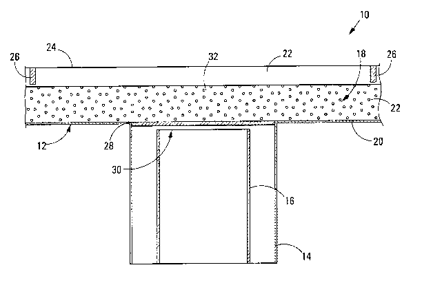
Referring to Figure 1 of the drawings, reference numeral 10 generally
indicates bulk particulate material microwave treatment apparatus in
accordance with
the invention. The apparatus 10 includes, broadly, a slightly inclined
vibrating or
oscillating base 12, a rectangular in horizontal section skirt 14 fastened to
the base 12
and extending from the base 12, and a stationary rectangular in horizontal
section
waveguide radiator 16 below the base 12.
The base 12 includes a U-shaped steel channel member which defines a
channel 18 with a microwave reflective inclined floor 20 and microwave
reflective side
walls 22. The side walls 22 are spaced about 150 mm from one another and the
channel 18 has a depth of about 140 mm.
The base 12 includes a microwave reflective cover 24 over the U-shaped
channel member. The base 12 and cover 24 together define a microwave treatment
zone. Two downwardly depending microwave choking shields 26 are provided
underneath the cover 24. The shields 26 are on opposite sides of the waveguide
radiator 16, one shield 26 in use being upstream of the waveguide radiator 16
and one
shield 26 in use being downstream of the waveguide radiator 16.
An opening is provided in the floor 20 of the channel member, directly above
the waveguide radiator 16. The opening is covered by a microwave transparent
rectangular ceramic panel or window 28 such that an upper surface of the
ceramic
window 28 is flush with an upper surface of the floor 20. The ceramic window
28 has
the same length and width as the skirt 14. As can be clearly seen in Figures 1
and 2 of
the drawings, the waveguide radiator 16 is vertically spaced from the ceramic
window
28, leaving an air gap.
The apparatus 10 includes a microwave generator or microwave pulse
generator (not shown) operable to feed microwaves into the waveguide radiator
16.
The waveguide radiator 16 is rectangular in transverse cross-section and has a
CA 02666399 2009-04-09
WO 2008/044218 PCT/IB2007/054158
9
rectangular microwave outlet 30. The microwave outlet 30 is in a plane which
is parallel
to the floor 20. The long sides of the outlet 30 are parallel to a
longitudinal axis of the
channel 18, with short sides of the microwave outlet 30 being arranged
transversely to
the channel 18 so that the microwave field in the outlet 30 is polarised
normal to the
side walls. In the embodiment of the invention shown in Figures 1 and 2, the
outlet 30
has a length of about 260 mm and a width of about 136 mm.
The waveguide radiator 16 passes through a microwave choke (not shown)
located inside the skirt 14.
The apparatus 10 includes a Faraday cage (not shown) around the base 12
and waveguide radiator 16 to protect operating personnel from residual
microwave
leakage. Typically, the Faraday cage is of expanded metal mess of 25 x 12 x 3
mm or
35x12x1.6mm.
The waveguide radiator 16 is of aluminium. At least around the microwave
outlet 30, the aluminium has a thickness of 6 mm that is chamfered to reduce
microwave field intensity on the edges of the waveguide radiator 16, thereby
reducing
the chances of arcing between the waveguide radiator 16 and the base 12.
The apparatus 10 can be used to treat, for example, banded iron ore, with a
particle size of say, 35 mm, with microwaves in order to liberate minerals
from the ore.
The ore is fed in the form of a 100 mm thick bed 32 along the U-shaped channel
member, by vibrating the base 12 in an oscillating fashion. The bed 32 thus
passes
over the ceramic window 28 and the microwave outlet 30. Continuous wave or
pulsed
microwaves from the microwave generator, fed by means of the waveguide
radiator 16,
are radiated into the bed 32 from below. With the waveguide radiator 16, an
electric
field 34 (see Figure 2) is generated across the width of the channel 18, which
is uniform
across the width of the channel 18. In a longitudinal direction, i.e. in the
direction of the
movement of the bed 32, the electric field 34 has a maximum 36 above the
microwave
outlet 30. The shields 26 also cause another set of standing waves between the
shields
26 and the microwave outlet 30, as shown in Figure 2 of the drawings.
CA 02666399 2009-04-09
WO 2008/044218 PCT/IB2007/054158
With reference to Figure 3 of the drawings, the waveguide radiator 16 and
the skirt 14 may be arranged at an angle to the vertical, and thus at an acute
angle to
the floor 20. In the embodiment of the apparatus shown in Figure 3, the
microwave
radiator 16 and the floor 20 define an acute angle 38 between them of about 32
.
Figure 3 also shows the predicted microwave field distribution in such
apparatus, which
is generally indicated by reference numeral 50.
Compared to the apparatus 10, the microwave transfer volume in the
apparatus 50 is larger, causing a smaller field density. A more homogenous
field
distribution is however obtained in the apparatus 50.
In Figure 4 of the drawings, the waveguide radiator 16 and the skirt 14 are
also arranged at an angle to the vertical, and thus at an acute angle to the
floor 20. In
the embodiment of the apparatus shown in Figure 4, the acute angle 38, the
depth of
the bed 32, and an air gap 62 between the bed 32 and the cover 24 are selected
such
that there is a single maximum 36 for the electric field 34, in the bed 32
above the
microwave outlet 30. Figure 4 shows the predicted microwave field distribution
in such
apparatus, which is generally indicated by reference numeral 60. By
manipulating the
height of the cover 24 above the bed 32, it is also possible to adjust the
vertical position
of the maximum 36 inside the channel 18, which forms part of a microwave
treatment
zone.
The applicant expects that, if plasma is formed during use of the apparatus
10, 50, 60 the plasma will move away from the microwave outlet 30, i.e.
generally
upwards. The plasma will thus not end up in the waveguide radiator 16, which
would
clearly be undesirable.