Note : Les descriptions sont présentées dans la langue officielle dans laquelle elles ont été soumises.
CA 02697089 2010-03-17
1 "PRODUCTION TUBING DRAIN VALVE"
2
3 FIELD OF THE INVENTION
4 Embodiments of the invention are related to valves used in production
tubing fluidly connected to submersible pumping assemblies and more
particularly,
6 to valves positioned above the submersible pumping assembly to drain fluid
from
7 the production tubing to the annulus when the pumping assembly is shutdown.
8
9 BACKGROUND OF THE INVENTION
Submersible pumping assemblies such as progressive cavity pumps
11 and centrifugal pumps are suspended downhole in a wellbore by a string of
12 production tubing. During pumping, fluid is discharged up the production
tubing by
13 the pump. When the pump stops, either intentionally or as a result of a
failure of the
14 pumping assembly, fluid in the production tubing string may flow back down
into the
pump causing the pump to reverse and potentially causing debris in the fluid
to
16 enter the pump. The debris remains in the pumping assembly and, when the
pump
17 is restarted, may cause damage to the pumping assembly.
18 Alternatively, in the case where an operator wishes to pull the pump
19 and the production tubing from the wellbore, such as for servicing of the
pumping
assembly, the pump and production tubing may pack off resulting in fluid
remaining
21 in the production tubing. In order to reduce the weight of the loaded
production
22 tubing for extraction from the wellbore, a bailing operation may be
required which is
23 both costly and time consuming.
1
CA 02697089 2010-03-17
1 It is known to provide a valve above the discharge of an electrical
2 submersible pump for draining the tubing above the pump when the pump shuts
3 down. US Patent 6,289,990 to Baker Hughes Incorporated teaches a tubing
shunt
4 valve which is pressure actuated between a sealed position, wherein fluid
communication between the production tubing and an annulus thereabout via
shunt
6 ports is prevented, and a drain position, wherein fluid is drained from the
production
7 tubing above the pump through shunt ports into the annulus. The Baker Hughes
8 valve utilizes a single diameter valve cage having a seal interface which
shifts
9 across the shunt ports when moving between the sealed and drain positions.
The
Baker Hughes valve utilizes a spring biased valve head and shaft forming a
piston
11 which is confined within a bore in the valve cage. The valve head seals
against a
12 valve seat formed in the valve cage in the drain position. The valve seat
is in fluid
13 communication with the discharge of the pump therebelow. The shifting of
the
14 sleeve to the sealed or production position is reliant upon a friction
resistance to
shifting of the valve cage being less than a fluid force required to open the
valve
16 head when biased to the drain position. Applicant believes that any
additional
17 resistance due to fouling could prevent shifting of the valve cage to seal
the shunt
18 ports even though the pump may have overcome the biasing spring to cause
the
19 valve head to unseat and fluid to pass through the valve seat and the
plurality of
axial passages in the valve cage.
21 Further, the spring which biases the valve head must be matched to
22 the depth of the well as a result of increasing hydrostatic pressure and
therefore
23 many iterations of the valve are required for use in wells of different
depths.
2
CA 02697089 2010-03-17
1 There is a need for a drain valve which reliably seals the shunt ports
2 through repeated movement of the valve between the sealed and drain
positions
3 and which is reliably and rapidly actuated between the sealed production
position
4 and the drain position when required.
6 SUMMARY OF THE INVENTION
7 A tubing drain valve utilizes a first check valve positioned below a
8 sleeve which is axially moveable in a housing, to form a downhole piston
face.
9 Pumped fluid, acting at the downhole piston face, result in a significant
positive
force to lift the sleeve to block one or more drain ports in the housing, in a
11 production position. Thus, the valve does not rely upon overcoming a
biasing force
12 to permit fluid communication with the formation and is less prone to
fouling. The
13 valve therefore minimizes failures to shift the sleeve to block the one or
more drain
14 ports in the production position.
A second check valve is positioned above the sleeve for forming an
16 uphole piston face when sealed against the sleeve. Produced fluid in the
production
17 tubing, upon stopping the pump, acts at the uphole piston face for shifting
the
18 sleeve downhole to open the one or more drain ports. The fluids are drained
19 through the one or more drain ports to the annulus.
In one broad aspect therefore, a tubing drain valve for incorporation
21 between a production tubing string and a pump, the tubing drain valve
comprising: a
22 housing having an uphole end for connection to the production tubing string
above
23 the pump and a downhole end for connection to the pump, downhole of the
3
CA 02697089 2010-03-17
1 housing, the housing having a valve bore in communication with fluid in the
tubing
2 string and the pump; one or more drain ports in the housing communicating
with the
3 valve bore; a sleeve fit to the valve bore and being axially moveable in a
4 reciprocating action in the valve. bore, the sleeve having a central bore
therethrough; a first check valve positioned downhole of the sleeve for
sealing the
6 central bore at a downhole end of the sleeve for forming a downhole piston
face,
7 fluid from the pump acting thereat to lift the sleeve uphole to block the
one or more
8 drain ports in a production position; and unsealing from the central bore
for
9 permitting fluid to flow therethrough in the production position; a second
check valve
positioned above the sleeve for unsealing from the central bore at an uphole
end of
11 the sleeve for permitting fluid to flow therethrough in the production
position; and
12 sealing the central bore for forming an uphole piston face, fluid in the
production
13 tubing string thereabove acting thereat to move the sleeve downhole to open
the
14 one or more drain ports in a drain position for draining fluid from the
production
tubing string therethrough.
16 The first and second check valves are spaced by a valve stem for
17 forming a check valve assembly which is freely, axially moveable in the
sleeve.
18 Spacing of a stop and an uphole shoulder in the housing permits the check
valve
19 assembly's axial, uphole movement to be stopped at the stop before the
sleeve's
axial, uphole movement is stopped by the uphole shoulder. This causes the
first and
21 second check valves to be unsealed from the sleeve for permitting uphole
flow of
22 fluids thereby in the production position.
4
CA 02697089 2010-03-17
1 In another broad aspect of the invention, a method for operating a
2 tubing drain valve, positioned between a production tubing string and a
pump, for
3 blocking one or more drain ports in a valve housing in a production position
for
4 producing fluid through a valve bore in the housing when the pump is
operating and
opening the one or more drain ports in a drain position for draining fluid
from the
6 production tubing when the pump is stopped, the method comprising: receiving
fluid
7 from the pump when operating the pump to flow fluid uphole; shifting a first
check
8 valve axially uphole to seal a central bore of a sleeve housed in the valve
bore at a
9 downhole end of the sleeve, for forming a downhole piston face; the fluid
acting at
the downhole piston face; lifting the sleeve to move axially uphole within the
valve
11 bore to block the one or more drain ports in the production position,
arresting the
12 uphole movement of the first check valve; and lifting the sleeve to unseal
at least
13 the first check valve from the central bore to permit the fluid to flow
therethough
14 receiving fluid from the production tubing when the pump is stopped for
ceasing the
flow of fluid uphole; moving a second check valve downhole to seal the central
bore
16 at an uphole end of the sleeve and for forming an uphole piston face, fluid
in the
17 production tubing thereabove acting at the uphole piston face; and shifting
the
18 sleeve downhole to open the one or more drain ports in the drain position.
19 Advantageously, providing a seal which remains above the drain ports
and a seal which remains below the drain ports extends the life of the seals
as
21 damage due to engagement of the seals with the drain ports is avoided.
22
23
5
CA 02697089 2010-03-17
1 BRIEF DESCRIPTION OF THE DRAWINGS
2 Figures 1A - 1C are longitudinal sectional views of a prior art drain
3 valve illustrating the sequential action of the valve, more specifically,
4 Fig. 1A illustrates a valve cage shifted downhole sufficient to
open shunt ports in a production tubing string and a piston therein biased to
6 a downhole position for sealing a valve seat in the valve cage fluidly
7 connected to a formation therebelow, fluid from the production tubing being
8 drained through the shunt ports to an annulus;
9 Fig. 1B illustrates the valve cage shifted to an uphole position
for closing the shunt ports and the valve head remaining biased to the
11 downhole position for preventing flow therethrough from the formation
below;
12 and
13 Fig. 1C illustrates the valve cage in the uphole position for
14 closing the shunt ports and the valve head shifted to a uphole production
position by pressure from the pump therebelow for opening the valve seat to
16 permit fluid flow to the production tubing string thereabove;
17 Figure 2A is a longitudinal sectional view of a drain valve according to
18 an embodiment of the invention, the valve being shown in a production
position;
19 Figure 2B is a longitudinal sectional view of a drain valve according to
another embodiment of the invention, the first check valve being shown
blocking a
21 bore of the housing;
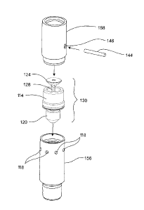
22 Figure 3 is an exploded perspective view of the drain valve according
23 to Fig. 2A
6
CA 02697089 2010-03-17
1 Figure 4 is a side view of a free floating check valve assembly axially
2 moveable within the drain valve according to Fig. 2A;
3 Figure 5 is a perspective plan view of a sleeve axially moveable within
4 a housing of the drain valve according to Fig. 2A illustrating a central
support
through which the free floating check valve assembly is mounted and a
plurality of
6 ports thereabout through which fluid is permitted to flow in a production
position;
7 Figure 6 is a plan view of the sleeve of Fig. 5;
8 Figure 7 is a side view of the free floating check valve assembly of
9 Fig. 4 in the sleeve of Fig. 5;
Figure 8 is a side view of a lower housing section of the drain valve of
11 Fig. 2A, illustrating a plurality of drain ports formed thereabout;
12 Figure 9 is a side view of an upper housing section of the drain valve
13 of Fig. 2A illustrating a opening for mounting a tag bar thereacross to
stop upward
14 travel of the check valve assembly therein; and
Figures 10A - 1OF are cross-sectional views of the drain valve
16 according to Fig. 2A in operation and illustrating axial movement of the
free floating
17 check valve assembly and the sleeve therein as a result of pressure
differentials
18 between the pump discharge therebelow and the hydrostatic head in a
production
19 tubing string thereabove; more particularly
Fig. 10A illustrates the free floating check valve assembly, after
21 pumping has stopped, having been moved axially downhole by pressure in
22 the tubing string, to seat an uphole end of the check valve assembly to an
23 uphole end of the sleeve for forming an uphole piston face;
7
4
CA 02697089 2010-03-17
1 Fig. 10B illustrates the drain valve in a drain position, the
2 uphole piston face having been acted on by the pressure of the fluids in the
3 tubing to move the check valve assembly and sleeve downhole to a
4 maximum extent within the housing for opening the drain ports to the
annulus;
6 Fig. 10C illustrates the drain valve when pumping is started, the
7 check valve assembly being shifted axially uphole to seat the downhole end
8 at a downhole end of the sleeve for forming a downhole piston face, the
9 downhole end of the check valve assembly preventing fluid flow from the
pump discharge therethrough;
11 Fig. 10D illustrates the pump discharge pressure acting on the
12 downhole piston face for shifting the free floating check valve assembly
and
13 sleeve axially uphole to close the drain ports;
14 Fig. 10E illustrates the pump discharge pressure continuing to
act on the downhole piston face for shifting the free floating check valve
16 assembly axially to a maximum extent for sealing the sleeve to the housing
17 above the drain ports and thereafter engaging an uphole end with a tag bar
18 in the housing, the downhole end of the check valve assembly preventing
19 fluid flow from the formation therethrough; and
Fig. 1OF illustrates the drain valve in a production position, the
21 sleeve shifted axially to a maximum extent, an uphole end of the sleeve
22 engaging a shoulder in the housing and the downhole end of the check valve
8
CA 02697089 2010-03-17
1 assembly being spaced below the downhole end of the sleeve for permitting
2 fluid flow therethrough from the formation to the production tubing string.
3
4 DETAILED DESCRIPTION OF THE PREFERRED EMBODIMENTS
Drain valves according to embodiments of the invention provide a
6 positive force for shifting a sleeve to close drain ports in a housing when
the drain
7 valve is shifted from a drain position to a production position. Thus, the
drain valve
8 more reliably closes the drain ports even when there is debris positioned
above the
9 sleeve which typically contributes to fouling of prior art valves.
In order to understand the unique and distinctive aspects of
11 embodiments of the invention, a more detailed description of the general
principles
12 of a known prior art drain valve are first set forth. Embodiments of the
present
13 invention are described thereafter.
14
Prior Art
16 As noted in the Background of the Invention herein, US Patent
17 6,289,990 to Baker Hughes Incorporated teaches a tubing shunt valve 10.
18 In operation, as shown in Figs. 1A-1C, when a pump (not shown)
19 connected to a production tubing string S below the shunt valve 10 begins
to
operate (Fig. 1B), fluid pressure P generated by the pump closes shunt ports
12 in a
21 body 13 of the tubing shunt valve 10. A valve cage 14, having a consistent
22 hydrodynamic diameter, is forced upwards. The pressure P, downhole from the
23 valve 10, acts against a piston 16, formed by the combination of a lower
end 18 of
9
CA 02697089 2010-03-17
1 the valve cage 14 and a spring-biased valve member 20 having a valve head
22,
2 housed therein. The valve head 22 initially closes a valve seat 24 (Fig.
113) in the
3 valve cage 14. Produced fluid does not initially pass uphole through valve
cage 14
4 because the valve head 22 is biased into sealing engagement with the valve
seat
24 by a spring 26.
6 The valve cage 14 moves upwards until an upper end 28 abuts an
7 upper interior rim 30 formed on an upper collar 32 in the valve body 13. A
seal 36
8 positioned below the shunt ports 12 is slid over the shunt ports 12 as the
valve cage
9 '14 slides over the shunt ports 12. A lower seal 37 positioned at a downhole
end of
the valve cage 14 remains below the shunt ports, thus sealing the shunt ports
12.
11 The valve cage 14 abutting the upper interior rim 30 is no longer
12 capable of further upward motion. Continued fluid pressure P from the pump
13 therebelow overcomes the spring 26 (Fig. 1C) forcing the valve member 20
and
14 valve head 22 to move upward out of sealing engagement with the valve seat
22 in
a production position. Well fluid then passes through the valve seat 24 and
upwards
16 through passages 34 in the valve cage 14 and through the production tubing
S
17 thereabove. When the valve cage 14 is in the production position, the shunt
ports
18 12 in the valve body 13 are closed by the valve cage 14. The resulting
closed shunt
19 valve 10 prevents communication between the production tubing and an
annulus
between the production tubing S and casing in the wellbore.
21 When the pump is shut down, a static column of produced fluid F is
22 within the tubing above the shunt valve 10. As the pump is shut down, fluid
pressure
23 P no longer acts upwards against the valve head 22. The spring 26 biases
the valve
CA 02697089 2010-03-17
1 head 22 downward until the valve head 22 is in sealing engagement with the
valve
2 seat 24, once again forming the piston 16. The static column of produced
fluid F
3 opens the shunt valve 10 by forcing the valve cage 14 downward until the
lower end
4 18 of valve cage 14 engages a lower interior rim 38 in the valve body 13
(Fig. 1A).
When the valve cage 14 is in this lower, drain position, openings 40 in the
valve
6 cage 14 are in alignment with the shunt ports 12. Produced fluid F is
allowed to
7 drain through the aligned ports 12, 40 to empty into the annulus. The
produced fluid
8 F will continue to flow out of the shunt ports 12 into the well annulus
until pressure
9 within the tubing string S and the annular area are equalized.
Applicant believes that it is apparent that if there is any resistance to
11 movement of the valve cage 14, due to debris in the produced fluid, the
spring
12 biased valve head 22 will open before the valve cage 14 moves and blocks
the
13 shunt ports 12, thus rendering the shunt valve 10 inoperative.
14
Embodiments of the invention
16 In a drain valve, according to embodiments of the invention, the valve
17 cage of the prior art is replaced by a tubular piston or sleeve which is
axially
18 moveable within a housing. The biased valve member of the prior art is
replaced by
19 a first check valve and a second check valve which engage downhole and
uphole
ends of the sleeve, respectively, for forming downhole and uphole piston faces
for
21 moving the sleeve axially within the housing to block and open drain ports
in the
22 housing, as described herein.
11
CA 02697089 2010-03-17
1 In greater detail and having references to Figs. 2A-9, the valve 100
2 comprises, a housing 110 having a valve bore 112 therethrough. The valve
bore
3 112 is in fluid communication with a string of production tubing thereabove
and with
4 a pump positioned therebelow. The production tubing and the pump are not
illustrated but are well known. A tubular sleeve 114 is housed within the
housing
6 110 and has a central central bore 116 formed therethrough. The sleeve 114
is
7 axially moveable in a reciprocating action within the housing 110. The
sleeve 114
8 moves uphole to block one or more drain ports 118 in the housing 110 in the
9 production position when the pump is operating and moves downhole to open
the
one or more drain ports 118 in a drain position to drain produced fluid F from
the
11 production tubing. When the pump is stopped., the fluid F flows through the
one or
12 more drain ports 118 to an annulus between the production tubing and
wellbore
13 casing.
14 As shown in Figs. 2A-4 and Figs. 1OA-1 OF, a first check valve 120 is
positioned below a downhole end 122 of the sleeve 114. The first check valve
120
16 is axially moveable in the valve's bore 112 below the sleeve 114. When the
first
17 check valve 120 is caused to move uphole to engage the sleeve's downhole
end
18 122, a downhole piston face DH is formed and the central bore 116 of the
sleeve
19 114 is sealed. Discharge of fluid from the pump acts at the downhole piston
face
DH, creating a force to move the sleeve 114 uphole to block the one or more
drain
21 ports 118. Uphole movement of the first check valve 120 is arrested and the
sleeve
22 114 is caused to move further uphole to unseal from the first check valve
120 for
12
CA 02697089 2010-03-17
1 opening the central bore 116 of the sleeve 114, permitting fluids to flow
thereby into
2 the production tubing thereabove, in the production position.
3 A second check valve 124 is positioned above the sleeve 114 and is
4 unsealed from the sleeve 114 in the production position to permit fluids to
flow
thereby. When the pump is stopped, the second check valve 124 falls through
6 gravity or is caused to move downhole to engage an uphole end 126 of the
sleeve
7 114, forming an uphole piston face UH. The central bore 116 of the sleeve
114 and
8 the housing 110 therebelow are sealed by the uphole piston face UH,
preventing
9 fluid to flow thereby to the pump below. The hydraulic head of the fluid F
in the
production tubing acts at the uphole piston face UH, creating a force to move
the
11 sleeve 114 axially downhole, opening the one or more drain ports 118 in the
drain
12 position. The fluid F drains out of the valve bore 112 through the one or
more drain
13 ports 118 to the annulus.
14 Having reference again to Figs. 2A-4, and in an embodiment of the
invention, the first and second check valves 120,124 are connected and spaced
16 apart by a valve stem 128 for forming a free floating check valve assembly
130. The
17 valve stem 128 has a length longer in a length of the sleeve 114 so as to
space the
18 first check valve 120 from the second check valve 124 and permit both first
and
19 second check valves 120, 124 to be unsealed from the sleeve 114 in the
production
position.
21 As shown in Figs. 5-7, the sleeve 114 further comprises a tubular
22 sleeve body 115 having a central central bore 116 and a central support
132,
23 supported in the central bore 116 for guiding the axially, freely-moveable
valve stem
13
CA 02697089 2010-03-17
1 128 therein. A flow passage 134 is formed circumferentially about the
sleeve's
2 central support 132. The flow passage 134, which may be a plurality of flow
ports,
3 permits pumped fluids to flow through the sleeve 114 when the drain valve
100 is in
4 the production position.
As seen in Fig. 2A, and in one embodiment, a downhole portion of the
6 valve's bore 112 has a reduced diameter 136 and the first check valve 120 is
sized
7 to seal therein for forming a check valve piston 138 in the drain position.
Discharge
8 from the pump acts on the check valve piston 138 to drive the check valve
piston
9 138 uphole out of the reduced diameter 136 to engage the downhole end 122 of
the
sleeve 114 for forming the downhole piston face DH.
11 Having reference to Figs. 2A, 2B, 3, 8 and 9, the housing 110
12 comprises an uphole shoulder 140 spaced from a downhole shoulder 142 for
13 limiting the maximal extent of the axial reciprocating movement of the
sleeve 114
14 between the production position and the drain position.
The housing 110 further comprises a stop 144 positioned above the
16 uphole shoulder 140. The stop 144 engages the second check valve 124 of the
17 check valve assembly 130 for arresting the uphole movement of the first
check
18 valve 120 connected thereto, before the sleeve 114 reaches the uphole
shoulder
19 140. This results in the sleeve 114 being able to continue to move uphole
and
unseal from the first check valve 120 in the production position for
permitting flow of
21 fluids thereby. The position of the stop 144 and the uphole shoulder 140
the spacing
22 of the first and second check valves 120, 124 and the spacing of the uphole
and
23 downhole ends 126,122 of the sleeve 114 co-operate to enable: the first
check
14
CA 02697089 2010-03-17
1 valve 120 to seal at the downhole end 126 of the sleeve 144 or the second
check
2 valve 124 to seal at the uphole end 122 of the sleeve 114 and for neither
the uphole
3 end 126 or the downhole end 122 of the sleeve 114 to be sealed to the check
valve
4 assembly 130 in the production position.
Having reference to Fig. 3, the stop 144 is a tag bar positioned across
6 the valve bore 112 of the housing 110. The tag bar 144 is typically inserted
into the
7 housing 110 through mounting holes 146 in the housing's wall.
8 As shown in Figs. 2A and 7, embodiments of the invention incorporate
9 a unique sealing arrangement for sealing above and below the one or more
drain
ports 118 in the production position and below the one or more drain ports 118
in
11 the drain position. The sleeve 114 has a stepped outer wall 148, which
forms a
12 major diameter Mj at the downhole end 122 and a minor diameter Mn at the
uphole
13 end 126. A seal 150 is housed in the major diameter Mj of the sleeve 114 to
seal
14 between the sleeve 114 and the housing 110 at a corresponding major
diameter
115 in the valve bore 112. The seal 150 remains below the one or more drain
ports
16 118 during reciprocation of the sleeve 114 between the production position
and the
17 drain position. The housing 110 is stepped inwardly above the one or more
drain
18 ports for forming a corresponding minor or reduced diameter 152. A seal 154
is
19 positioned between the sleeve's minor diameter Mn and the valve bore 116.
As
shown in Fig. 2A, the seal 154 is housed in the housing's reduced diameter 152
to
21 seal against the minor diameter Mn of the sleeve 114 when the sleeve 114 is
22 moved uphole to the production position. Thus, sliding contact between the
seals
CA 02697089 2010-03-17
1 150,154 and the one or more drain ports 118, which could act to prematurely
wear
2 the seals, is avoided.
3 As shown in Figs. 2A, 213, 3, 8 and 9, in embodiments of the invention
4 for the purposes of manufacture, the housing 110 comprises a lower tubular
housing 156 and an upper tubular housing 158. The upper and lower housings
6 156,158 together define the valve's bore 112, in which the sleeve 114 and
check
7 valve assembly 130 are mounted.
8 In one embodiment best seen in Figs. 2A, 3, 8 and 9, the lower
9 housing 156 comprises the one or more drain ports 118 formed adjacent an
uphole
end 160, the downhole shoulder 142 and the downhole reduced diameter portion
11 136. The upper housing 158 comprises the inwardly stepped, reduced diameter
152
12 at a downhole end 162 which houses the seal 154 which engages the sleeve's
13 minor diameter Mn, the uphole shoulder 140 and the mounting holes 146 for
the tag
14 bar 144, positioned thereabove.
Fig. 2B illustrates another embodiment for manufacture of the housing
16 120 wherein the lower housing 156 comprises the downhole reduced diameter
bore
17 portion 136 and forms the downhole shoulder 142. The upper housing 158
18 comprises the one or more drain ports 118 and the uphole shoulder 140. The
seal
19 154 is housed about the minor diameter Mn of the sleeve 114 which seals to
the
housing's reduced diameter 152, above the one or more drain ports 118.
21
16
CA 02697089 2010-03-17
1 In Operation
2 In operation, as illustrated in Figs. 10A through 10F, embodiments of
3 the drain valve 100 operatively shift between a drain position (Fig. 10B)
and a
4 production position (Fig. 10F), substantially through fluid actuation.
As shown in Fig. 10A, after the pump is stopped, the second check
6 valve 124, is moved downhole to engage the uphole end 126 of the sleeve 114.
The
7 second check valve 124 and the sleeve 114 form the uphole piston face UH
which
8 seals the flow passage 134 of the central bore 116 through the sleeve 114
and
9 therefore seals the valve' bore 112 therebelow.
As shown in Fig. 106, produced fluid F in the production tubing above
11 the uphole piston face UH acts at the uphole piston face UH to shift the
sleeve 114
12 downhole to open the one or more drain ports 118. The produced fluid F is
drained
13 through the one or more open drain ports 118 to the annulus thereabout.
14 As shown in Fig. 10C, when the pump is operating, fluid is received
from the pump and the first check valve 120 is shifted uphole to engage the
16 downhole end 122 of the sleeve 114 for forming the downhole piston face DH.
In
17 the case of a reduced diameter 136, the fluid positively drives the first
check valve
18 120 out of the reduced diameter 136 to engage the sleeve 114. The downhole
19 piston face DH seals the flow passage 134 through the sleeve 114 and the
valve
bore 112 thereabove.
21 As shown in Fig. 10D, fluid from the pump acts at the downhole piston
22 face DH to lift the sleeve 114 uphole to block the one or more drain ports
118.
17
CA 02697089 2010-03-17
1 As shown in Fig. 10E, the sleeve 114 engages the upper seal 154 to
2 seal against the housing 110 above the one or more drain ports 118 and
thereafter,
3 uphole movement of the first check valve 120 is arrested.
4 As shown in Fig. 10F, thereafter the sleeve 114 is further shifted
axially uphole to unseal from the first check valve 120 for opening the flow
passage
6 134. Fluid from the pump flows uphole through the flow passage 134 to the
7 production tubing thereabove.
8 The method is described herein in greater detail for an embodiment
9 wherein the first and second check valves 120,124 are spaced apart by the
valve
stem 128, forming the check valve assembly 130.
11 After the pump[ is stopped (Fig. 10A), the check valve assembly 130,
12 having been restrained at the tag bar 144 during production, is caused to
move
13 downhole such as by gravity or under the influence of produced fluid F
received
14 from the production tubing S thereabove. The second check valve 124 engages
(A)
the sleeve's uphole end 126, forming the uphole piston face UH. The produced
fluid
16 F in the production tubing thereabove acts at the uphole piston face UH to
create a
17 force for moving the check valve assembly 130 and sleeve 114 downhole as a
18 unitary piston.
19 Having reference to Fig. 10B, the valve 100 is shown in the drain
position. The sleeve 114 and check valve assembly 130 are shifted downhole
until
21 the sleeve's downhole end 122 engages the downhole shoulder 142 in the
valve
22 bore 112. The one or more drain ports 118 are opened to permit the produced
fluid
23 F to drain from the production tubing to the annulus. The first check valve
120 seals
18
CA 02697089 2010-03-17
1 in the downhole, reduced diameter portion 136 of the valve bore 112 forming
the
2 check valve piston 138 therein.
3 As shown in Fig. 10C, when the pump is started and is operating, the
4 discharge fluid flow from the pump is received and acts at the check valve
piston
138, positioned below the sleeve 114, to shift the check valve assembly 130
axially
6 uphole until the first check valve 120 engages (B) the downhole end 122 of
the
7 sleeve 114 forming the downhole piston face DH.
8 Having reference to Fig. 10D, the discharge fluid from the pump
9 continues to act at the check valve piston 138 to shift the sleeve 114 and
the check
valve assembly 130 axially uphole within the valve bore 112. The check valve
piston
11 138 moves uphole out of the reduced diameter portion 136 of the valve bore
112.
12 Thereafter, the discharge fluid acts at the downhole piston face DH created
by the
13 engagement (B) of the first check valve 120 with the downhole end 122 of
the
14 sleeve 114.
As shown in Fig. 10E, the discharge fluid continues to act at the
16 downhole piston face DH to shift the check valve assembly 130 and sleeve
114
17 uphole to block the one or more drain ports 118. The sleeve 114 seals to
the
18 housing 110 at seal 154 thereabove. Thereafter, the second check valve 124
19 engages (C) the tag bar 144, arresting further uphole movement of the check
valve
assembly 130. The first check valve 120 remains engaged at the downhole end
122
21 of the sleeve 114, preventing flow of discharge fluids through the sleeve's
flow
22 passage 134.
19
CA 02697089 2010-03-17
1 Thereafter, as shown in Fig. 1 OF, the discharge from the pump acts at
2 the major diameter Mj at the downhole end 122 of the sleeve 114 to shift the
sleeve
3 114 axially uphole, independent of the check valve assembly 130. The sleeve
114
4 is shifted uphole until the sleeve's uphole end 126 engages the uphole
shoulder 140
(D) in the valve bore 112, the sleeve 114 unsealing from the first check valve
120
6 for opening the flow passage 134 through the sleeve 114.
7 The valve stem 128 is of sufficient length such that when the second
8 check valve 124 has engaged the tag bar 144 and the sleeve 114 has engaged
the
9 uphole shoulder 140, both the first and second check valves 120,124 are
spaced
from the downhole and uphole ends 122,126 of the sleeve 114, opening the flow
11 passage 134 therethrough. Thus, discharge flow from the pump is permitted
to flow
12 past the first check valve 120 into the fluid ports 134 in the sleeve 114
and from the
13 fluid ports 134 in the sleeve 114 past the second check valve 124 to the
production
14 tubing S thereabove.
In an embodiment of the invention, as the sleeve 114 is moved axially
16 uphole to close the one or more drain ports 118, the minor diameter Mn of
the
17 sleeve 114 passes the one or more drain ports 118 without contact. The
sleeve 114
18 remains sealed to the housing 110 at the major diameter Mj, below the one
or more
19 drain ports 118 throughout the uphole movement of the sleeve 114. Thus, the
life of
the seals 150,154 is extended as damage due to engagement of the seals 150,154
21 with the one or more drain ports 118 is avoided.
22
23
CA 02697089 2010-03-17
1 EXAMPLE
2 A tubing drain valve according to an embodiment of the invention is designed
3 for use with 2-7/8 inch external upset end (EUE) tubing. The valve is
designed to
4 operate at a pressure of 5,000 psi and at a design temperature of 150 F. The
design flow rate is 50-1000 bbl/day. The valve is pressure-actuated as
discussed
6 herein and the materials for manufacture of the drain valve are selected to
be
7 compatible with produced fluids containing at least oil, water, solids,
associated gas
8 and CO2.
9
21