Note : Les descriptions sont présentées dans la langue officielle dans laquelle elles ont été soumises.
CA 02701664 2010-04-01
WO 2009/043851 PCT/EP2008/063092
- 1 -
INTEGRATED HEATER FOR A BEVERAGE PREPARATION DEVICE
Field of the Invention
The present invention concerns an integrated heater
for the heating of a liquid in a beverage preparation
machine.
Background Art
In-line heaters for heating circulating liquid, in
particular water, using thick-film technology have been
known for a number of years.
EP 0 485 211 discloses a heater for a water heater,
shower, washing machine, dishwasher or kettle. The heater
includes a vessel for heating liquid, and an electric
heating element which is arranged to heat a portion of
the vessel. The heating element incorporates a thick-film
resistive heating circuit with a thermal fuse included in
the thick-film. The document further discloses a triac-
type power regulator mounted directly on the heating
element that acts as a heat sinker for this triac. Also
disclosed is the presence of a thermistor, a temperature
sensor, formed on the thick film, a thermal fuse, a flow
control valve to continuously adjust the flow rate
through the heater, a flow control and a temperature
control. These electrical components are connected to a
control unit that can be remote or formed as part of the
dielectric layer of the thick film at a location close to
the inlet pipe where the heater's metal substrate is kept
cool by incoming cold water.
DE 197 32 414 discloses a heater that has a metal
through-flow passage with an inlet and an outlet and at
least one thick film heating element for heating water
that circulates in the passage. The thick film heating
element extends between the inlet and outlet on the outer
surface of the heater. The thick film heating element has
a tapered cross-section continuously decreasing in size
CA 02701664 2010-04-01
WO 2009/043851 PCT/EP2008/063092
- 2 -
from the inlet to the outlet. The decreasing section of
the thick film and the thus resulting decreasing heat
transfer along the passage inhibits accumulation of scale
at the end of the passage. The heater may include
temperature sensors near the inlet or outlet in the form
of thick-film elements. The same idea is disclosed in DE
103 22 034 which concerns a heater having a water
circulation passage extending between an outer shell and
an inner tube, the shell and/or the inner tube is covered
with a thick-film heating element. The water circulation
passage may be delimited by a helicoidal fin. The section
of the water circulation passage and/or the heating power
of the thick-film decrease along the direction of flow.
The decreasing heat transfer along the tube is provided
to avoid evaporation of water in the heater. The heater
may incorporate at the shell or inner tube temperature
sensors of the NTC or PTC type in thick-film technology.
Another heater with a helicoidal heating conduit is
disclosed in DE 197 37 694.
The use of thick-film and other resistive heater
technology is also known for hot beverage preparation
machines.
US 5,943,472 discloses a water circulation system
between a water reservoir and a hot water or vapor
distribution chamber of an espresso machine. The
circulation system includes a valve, metallic heating
tube and pump that are connected together and to the
reservoir via different silicone hoses, which are joined
using clamping collars.
WO 01/54551 (in the name of the applicant) concerns
a liquid heating module for use in a hot beverage machine,
which comprises a hollow tube of metallic material and a
cylindrical insert located inside the hollow tube. The
module incorporates an electrical thick-film resistor on
a first part of the outside of the tube for preheating
liquid and another electrical resistor on a second part
of the outside of the tube for adjusting the temperature
of the preheated liquid flowing through the tube. A
further electrical resistor for measuring the temperature
is incorporated at the module's inlet or outlet. In an
CA 02701664 2010-04-01
WO 2009/043851 PCT/EP2008/063092
- 3 -
embodiment, the heating module is supplied with water via
a pump and is connected at its outlet to a conduit for
circulating heated water to a coffee extraction chamber.
WO 2004/006742 (in the name of the applicant)
discloses a further tubular heating device for beverage
preparation machines having a plurality of thick-film
resistors that can be empowered in various configurations
to adjust the heating. The heating device has an outer
hollow metallic tube and an insert made of plastic,
metallic or ceramic material. The insert has helicoidal
grooves for guiding and circulating water between the
outer tube and the insert. The insert may be hollow and
may be used for a reversed flow of part of the hot water.
US 7,286,752 discloses a similar thick-film tubular
heater with an internal helicoidal water circulation
conduit.
Summary of the Invention
A preferred object of the present invention is to
simplify and improve the incorporation of the heating
function in a liquid food or beverage preparation machine
to facilitate and permit an increased automation of the
assembly of the machine, reduce the manufacturing
operations and costs and increase the reliability of the
machine.
This object is in particular achieved by providing a
heating system that integrates electrical and fluid
connections without requiring any flexible and deformable
cable or tubes, for guiding current or liquid, to connect
the heating function to other functional units of the
liquid food or beverage preparation machine, or at least
to limit the number of such flexible connections.
Therefore, the present invention relates to an in-
line heater for a liquid food or beverage preparation
machine, in which liquid, such as water, is circulated
through this heater and then guided into a brewing
chamber for brewing a food or beverage ingredient
supplied into this brewing chamber. This heater comprises:
CA 02701664 2010-04-01
WO 2009/043851 PCT/EP2008/063092
- 4 -
a body incorporating an inlet, an outlet and a heating
chamber extending therebetween, the inlet, outlet and
heating chamber forming together a rigid passage, in
particular a free-flow passage, for guiding this liquid
circulating through this body; and a heating means, in
particular a thick-film, cooperating with the body for
supplying heat into this heating chamber.
The body is normally made of a material that is
thermally highly conductive and preferably has a low
thermal inertia to avoid delay between the heat
generation by the heating means and transmission of the
generated heat to the liquid circulating in the body. The
material of the body which separates the heating means
and the liquid circulating in the chamber may be metallic
or metal based, such as steel or copper.
The resistive heating means may include wires and/or
thick-film(s) . The thick-film technology is known in the
art, as discussed above, and may use inks (like paste)
that can be applied to a surface of the body and that can
be made of quartz, metal, alumina or beryllium oxide. The
thick-film is typically applied onto the outside surface
of the body and is made of an electrically insulating
coating, such as plastic or enamel painting, on the body,
a layer of a resistive heating track on the insulating
coating and optionally a further layer, such as a plastic
layer, protecting the insulating coating and the
resistive heating track.
In accordance with the invention, the heater body
has an outer face arranged to delimit an upstream part of
the brewing chamber, the rigid passage of the body
extending into the brewing chamber. Hence, an outer part
of the heater does not merely serve to confine the
heating chamber but also to form part of the extraction
chamber. It follows that instead of having to provide a
heating element, a upstream part of the brewing chamber
and a fluid connecting member therebetween, a single
component appropriately shaped, combines all these
functions reducing thereby significantly the number of
parts, the number of assembly operations and the risk of
CA 02701664 2010-04-01
WO 2009/043851 PCT/EP2008/063092
- 5 -
failure due to improper handling of these parts and/or
improper assembly of the beverage preparation machine.
Typically, the brewing chamber is arranged to
contain a food or beverage ingredient, such as powder
soup, ground coffee or tea optionally in a capsule or a
pod, and has an upstream part into which hot liquid is
injected for brewing the food or beverage ingredient
containing in the chamber and a downstream part leading
into an outlet for guiding the liquid food or beverage
produced by brewing.
The heater body's outer face may include: one or
more protruding walls to delimit the upstream part of a
brewing chamber; and/or connecting means for mechanical
connection to a member delimiting a downstream part of
the brewing chamber.
In one embodiment, the heater's body comprises a
generally tubular or prismatic outer member that is
covered with this heating means, in particular a thin-
wall tubular or prismatic outer member having a thermal
inertia that is lower than aluminum, the generally
tubular or prismatic outer member having optionally a
base that forms this outer face of the body.
The body may be a thin-wall envelope and/or further
include an inner core, in particular an insert, that
delimits with the outer member the heating chamber, the
inner core being optionally generally coextensive and/or
generally concentric with respect to the tubular or
prismatic outer member. The insert can be made of plastic,
metal and/or ceramic material, such as PA, POM or steel.
The insert may be fixed or rotatable, as for instance
disclosed in EP 1 253 844 and EP 1 380 243.
The heating chamber can be generally helicoidal
around the core, in particular a chamber formed by a
generally helicoidal groove or flange around the core, as
for instance disclosed in EP 1 380 243.
Especially when the body is used with its helicoidal
heating chamber extending along a horizontal or low slope
axis, the inner core can be generally eccentric with
CA 02701664 2010-04-01
WO 2009/043851 PCT/EP2008/063092
- 6 -
respect to the tubular or prismatic outer member. In this
configuration, the chamber is arranged so that the size
of its cross-section changes along the chamber, to
increase the flow velocity in areas, usually upper areas,
which might otherwise serve to capture bubbles, in
particular vapor bubbles. The increased liquid velocity
in these areas "washes" the bubbles down and away from
this area with the fast flow of liquid in this area. To
avoid overheating in such areas with reduced cross-
section, the heating power may be reduced on the
corresponding parts of the heater, for instance, by
adjusting the resistive means on these parts.
One or more electric components may be secured on or
in the body of the heater. The electric components can be
selected from temperature sensors, thermal fuses, flow
meters, resistive heaters, ammeters and electric power
regulators and similar components. One or more electric
components may be connected to a printed circuit board
(PCB) arranged to control this heater and optionally
control further functions, such as a pump or an electric
interface, of a beverage preparation machine arranged to
contain this heater. The electric components on the body
may be discrete components mechanically connected to the
body and/or integrated components, for instance formed
directly into the resistive thick-film layer. Typically,
thermal fuses and temperature sensors may be formed in
thick-film technology together with the resistive heater.
To reduce the number of assembly operations, in
particular human interventions during the manufacturing
process, the number of flexible, deformable, electric
cable connections may be reduced. In particular, the
electric components can be rigidly connected to this
printed circuit board, for instance via rigid connector
pins or blades or rigid plug and socket members. In such
a way, the electric components, in particular those which
come into contact with the liquid circulation system such
as the heater or even the pump, can be mounted
automatically on the printed circuit board and then the
board with the components is assembled (for instance
clipped) automatically onto the liquid circulation system
without any flexible, deformable electric connectors (e.g.
CA 02701664 2010-04-01
WO 2009/043851 PCT/EP2008/063092
- 7 -
cables) between the board and the liquid circulation
system. Alternatively, the electric components may be
automatically mounted in a first step at dedicated
locations of the liquid circulation system and then, in a
second step, the printed circuit board is assembled, for
instance via an appropriate connector, to the electric
components. It is also contemplated to assemble by
welding the electric components to the liquid circulation
system, in particular to the heater and/or to the printed
circuit board.
Another aspect of the invention relates to an in-
line heater for a liquid food or beverage preparation
machine, in which liquid is circulated through this
heater and then guided into a brewing chamber for brewing
a food or beverage ingredient supplied into this brewing
chamber. This heater comprises: a body incorporating an
inlet, an outlet and a heating chamber extending
therebetween, this inlet, outlet and heating chamber
forming together a rigid passage for guiding this liquid
circulating through this body; a heating means, in
particular a resistive heating means such as a thick-film,
cooperating with the body for supplying heat into this
heating chamber; and one or more electric components,
such as sensors, thermal fuses and/or electric power
components, that are secured on or in the body and
connected to a printed circuit board arranged to control
this heater and optionally further functions of this
liquid food or beverage preparation machine.
In accordance with the invention, one or more
electric components are rigidly connected to this printed
circuit board, in particular via rigid connector pins or
blades or rigid plug and socket members. By avoiding the
use of flexible, deformable cables, the number of
operations during the assembly process is reduced, in
particular the number of human interventions is reduced.
Hence, the manufacturing and assembly costs are
correspondingly reduced as well as the risks of failure
due to human error. By avoiding flexible and deformable
cable connections, automation of the assembly may be
increased.
CA 02701664 2010-04-01
WO 2009/043851 PCT/EP2008/063092
- 8 -
For instance, these electric components may comprise
a power component, in particular a resistive heating
means such as a thick-film, which is rigidly connected
via a rigid electric power pin and a rigid power
connector. This power connector has a socket for
receiving the rigid electric pin, the rigid connector
being resilient, in particular made of one or more spring
blades, to allow displacements of the socket for self-
positioning the socket around the pin and to secure
electric contact between the pin and the connector.
Furthermore, one or more features described above
may be conveniently combined with this in-line heater.
The invention also relates to an electric power
connector, in particular for a heater as described above.
The power connector comprises a pair of spaced apart feet
for connection to a current supply circuit. Each foot is
connected to a first rigid spring member, the first
spring members being connected together via a second
rigid spring member. The second member has a socket for
receiving and securing a rigid electric pin. The first
and second spring members are resiliently displaceable
along different directions, in particular perpendicular
directions, for self-positioning the socket with respect
to said rigid electric pin and to provide an electric
connection permitting passage of high current
therethrough. At least one of the first spring members
and the second spring member may be generally blade-
shaped. The first spring members and the second spring
member can be generally M-shaped so as to allow
displacements of the socket along two directions
substantially in a single plane.
A further aspect of the invention relates to an in-
line heater for a liquid food or beverage preparation
machine, in which liquid is circulated through this
heater and then guided into a brewing chamber for brewing
a food or beverage ingredient supplied into said brewing
chamber. This heater comprises: a body having a generally
tubular or prismatic outer member and an inner core that
is generally coextensive with respect to the tubular or
prismatic outer member, the tubular or prismatic outer
CA 02701664 2010-04-01
WO 2009/043851 PCT/EP2008/063092
- 9 -
member and the inner core delimiting together a generally
helicoidal heating chamber extending therebetween and
around the inner core; and a heating means, in particular
a resistive heating means such as a thick-film, covering
the tubular or prismatic outer member for supplying heat
into said heating chamber.
According to the invention, the inner core is
eccentric with respect to the tubular or prismatic outer
member so that the helicoidal heating chamber has a
variable cross-section around the inner core.
As mentioned above, especially when the body is used
with its helicoidal heating chamber extending along a
horizontal or low slope axis, providing an inner core
that is eccentric with respect to the tubular or
prismatic outer member leads to a chamber that is
arranged so that its cross-section varies along its
length, so as to increase the flow velocity in areas
which might otherwise capture bubbles, in particular
vapor bubbles. Thus, by providing an increased flow
velocity in these areas, the bubbles are "washed" away
therefrom by the fast flow of liquid. In such a manner,
the relative positioning of the insert relative to the
tubular or prismatic outer member solves the problem of
bubble accumulation without having to include complex
movable mechanical systems (e.g. a rotatable insert) that
would push the bubbles out from the heater. Hence,
providing a heater with an eccentric insert leads to a
reduction of the number of parts and assembly operations
and costs of manufacture.
One or more features described above may of course
be conveniently combined with this in-line heater.
A yet further aspect of the invention relates to a
liquid food or beverage preparation machine comprising a
heater as described above. The machine may be suitable to
prepare liquid food such as soup, tea and/or coffee by
brewing a food or beverage ingredient that may optionally
be contained in capsule or a pod.
Another aspect of the invention relates to a liquid
food of beverage preparation machine, in particular as
CA 02701664 2010-04-01
WO 2009/043851 PCT/EP2008/063092
- 10 -
described above. The machine comprises: an electric
supply circuit connectable to an electric power source; a
heater powered by the electric supply circuit; and a
thermal fuse device in thermal communication with the
heater and associated with the electric supply circuit.
The fuse device is arranged to interrupt the electric
supply circuit from the power source when the heater
exceeds a temperature limit.
In accordance with the invention, the thermal fuse
device is reversible and comprises a switch for
automatically interrupting the electric supply circuit
when the heater exceeds this temperature limit. The
switch is operable by a user to close the electric supply
circuit when the heater has a temperature that has
returned below said temperature limit. Typically, the
fuse device comprises an actuator that is arranged to
push out a pin, rod or piston against the user switch
when this temperature limit is exceeded by the heater so
as to actuate the user switch and open the circuit.
This beverage or liquid food machine may include any
of the above disclosed features or combination of
features.
The fuse device may have an actuator which comprises
a thermo-mechanical component that is in thermal
communication with the heater and that mechanically
actuates the user switch to open the electric supply
circuit when the heater exceeds the temperature limit.
The thermo mechanical component comprises in particular a
shape memory element or a bimetal element.
The fuse device can include a safety electric
temperature sensor in thermal communication with the
heater and an electromechanical actuator that actuates
the user switch to open the electric supply circuit when
the safety sensor is exposed to a temperature generated
by the heater which exceeds the temperature limit.
In one embodiment, the beverage or liquid food
machine has a printed circuit board with a control
circuit for controlling the heater and optionally further
functions of the machine, such as a pump or an electric
CA 02701664 2010-04-01
WO 2009/043851 PCT/EP2008/063092
- 11 -
interface, the printed circuit board further including a
safety circuit that is electrically separated on the
printed circuit board from the control circuit, the
safety circuit being connected to the safety sensor, in
particular rigidly connected to the safety sensor, and
arranged to control the electromechanical actuator.
At least part of the fuse device, in particular the
actuator, electromechanical or thermo-mechanical actuator,
the user switch and/or, when present, the safety sensor,
may be rigidly connected to a printed circuit board of
the liquid food or beverage machine, optionally on a part
that is electrically insulated from an ordinary control
unit of the machine, e.g. a unit for controlling the
usual operations of the machine such as beverage or
liquid food dispensing, self-cleaning, user-interface,
etc... Hence, assembly and integration and safety of the
fuse device into the liquid food and beverage machine is
improved.
Brief Description of the Drawings
The invention will now be described with reference
to the schematic drawings, wherein:
- Figures 1 to 3 show various details of a heater
according to the invention;
- Figures 4 and 5 show another heater according to
the invention;
- Figure 6 shows yet another heater according to the
invention;
- Figures 7 and 8 show the assembly of an electric
power component to a heater and to a printed circuit
board in accordance with the invention;
- Figures 9 and 10 show the assembly of a sensor to
a heater and to a printed circuit board in accordance
with the invention;
- Figure 11 shows an electric power connection
between a heater and to a printed circuit board in
accordance with the invention;
CA 02701664 2010-04-01
WO 2009/043851 PCT/EP2008/063092
- 12 -
- Figures 12a and 12b illustrate a deflection
according to a first direction of the power connection
shown in Figure 11; and
- Figures 13a and 13b illustrate a deflection
according to a second direction of the power connection
shown in Figure 11.
- Figures 14 and 15 schematically illustrate two
embodiments of the invention of an electric circuit of a
beverage machine with a user-reversible safety fuse in
accordance with the invention.
Detailed description
Figures 1 to 3 illustrate an in-line heater
according to the invention, Fig. 1 being a front
perspective of the heater, Fig. 2 being a rear
perspective of this heater and Fig. 3 being an exploded
view of the same heater. The heater is suitable for a
liquid food or beverage preparation machine, in which
liquid is circulated through a heater and then guided
into a brewing chamber for brewing a food or beverage
ingredient supplied into the brewing chamber. For
instance, a beverage ingredient is supplied to the
machine in prepackaged form, for example contained in a
capsule or in a pod. Typically, this type of liquid food
or beverage machine is suitable to prepare coffee, tea
and/or other hot beverages or even soups and like food
preparations. The pressure of the liquid circulated to
the brewing chamber may for instance reach about 10 to 20
atm.
The heater has a body 1 incorporating an inlet 2, an
outlet 3 and a helicoidal heating chamber 4 extending
therebetween. Inlet 2, outlet 3 and heating chamber 4
forming together a rigid passage for guiding liquid
circulating through body 1.
The heater further includes a heating means 5 in the
form a resistive thick-film that extends as a helicoidal
track between two connector areas 5',5" over body 1 and
CA 02701664 2010-04-01
WO 2009/043851 PCT/EP2008/063092
- 13 -
cooperates with the body for supplying heat into heating
chamber 4 located underneath thick-film 5.
Heater body 1 has an outer face 6 arranged to
delimit an upstream part of a brewing chamber 7, the
rigid passage, in particular outlet 3, of body 1
extending into brewing chamber 7. As shown schematically
in Figures 1 and 3, outer face 6 includes an annular
protruding wall 6' for delimiting the upstream part of
brewing chamber 7.
As illustrated in Figures 1 to 3, body 1 has a
generally tubular outer member 8 that is covered with the
heating means 5. Member 8 has a thin wall made of
thermally highly conductive material and of low inertia,
such as steel, to promote transfer of heat generated by
the heating means 5 formed thereon. This generally
tubular outer member 8 cooperates with a base member that
forms the outer face 6 of body 1.
Outer face 6 is shown extending peripherally over
the edge of tubular member 8. Moreover, annular wall 6'
delimiting the upstream portion of brewing chamber 7, is
generally coaxial with outlet 3 and has a diameter that
is smaller than the diameter of tubular member 8.
In a variation, the upstream portion of brewing
chamber 7 may be formed integrally with tubular member 8
and/or annular wall 6' may have an outermost surface that
is co-extensive with the outer surface of tubular member
8 to further simplify its geometry. Such a configuration
is shown in Figure 6.
Body 1 of Figures 1 to 3 further includes an inner
core 9, in particular a hollow tubular or cylindrical
insert, with a peripheral protruding helicoidal guiding
wall 91. Inner core 9 is generally coextensive and
concentric with respect to tubular outer member 8, and
delimits with outer member 8 helicoidal heating chamber 4.
In a variation, a helicoidal groove may be provided
around the inner core instead of the protruding guiding
wall. The groove or wall may also be formed on the inner
face of the tubular outer member. Inner core 9 may be
CA 02701664 2010-04-01
WO 2009/043851 PCT/EP2008/063092
- 14 -
made of metal or of a material that is less heat
conductive such as plastic or ceramic material.
One or more electric components, such as sensors
and/or electric power elements, are secured in body 1 in
a housing 3' located around outlet 3. The electric
components may include one or more of: temperature
sensors, thermal fuses, flow meters, resistive heaters
and electric power regulators.
Housing 3' and the therein contained electric
components may be connected via rigid data transfer
connectors to a printed circuit board (not shown).
In a variation, the electric components may be
assembled into tubular outer member 8. In particular, the
power element, for instance a triac, for adjusting the
electric current passed via the resistive heating means 5
may be located in the heater close to the circulating
liquid so that the circulating liquid may serve as a
cooler for the power component.
Also shown in Figure 3 is a sealing means 9' on
insert 9 to prevent the leakage of liquid between tubular
outer member 8 and insert 9. Sealing means 9' may be
integral with tubular outer member 8 or insert 9 or a
separate member 9' between member 8 and insert 9, such as
an o-ring or another deformable seal, or a seam formed by
welding.
Figures 4 and 5, in which the same numeric
references designate the same elements show another
heater according to the invention.
Heater body 1 has an inner core 9 which is generally
coextensive and eccentric with respect to the tubular
outer member 8. Hence, the helicoidal heating chamber 4
has variable cross-section around inner core 9. In
particular, along one side of outer member 8 and insert 9,
the cross-section 4' of heating chamber 4 is
significantly smaller than the cross-section 4'' along
the opposite side of outer member 8 and insert 9.
CA 02701664 2010-04-01
WO 2009/043851 PCT/EP2008/063092
- 15 -
Thus, when the heater is not used in a vertical
position, i.e. in a position in which the longitudinal
central axis 8a of outer member 8 is not vertical but
horizontal or at an angle which does not allow
spontaneous escape of bubbles from helicoidal chamber 4
to outlet 3. The increase of liquid velocity where the
cross-section 4' of helicoidal chamber 4 narrows down
permits to flush any bubbles contained in that upper area
of chamber 4 to the lower area of chamber 4 with larger
cross-sections 411, and so on until the bubbles reach
outlet 3.
Furthermore, in order to avoid overheating and to
inhibit the deposition of scale in the parts of chamber 4
with narrowed cross-sections 4', the heating power of
heating means 5 may be reduced over a portion 5" ' as
indicated on Figure 5 by the notional generally
rectangular section 5.... intercepting heating element 5
on tubular outer member 9. Portion 5" " may extend along
tubular outer member 9 over an arc of about 15 to 90 , in
particular 30 to 60 deg of the tubular outer member 9,
as measured from the central longitudinal axis 8a of
tubular member 8.
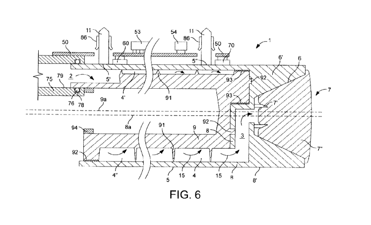
Figure 6, in which the same numeric references
designate the same elements, schematically shows another
embodiment of a heater according to the invention. The
heater's body 1 has a generally tubular outer steel
member 8 and an insert in the form of a generally tubular
plastic hollow inner core 9 with a peripheral helicoidal
flange 91 that delimits with an inner surface of member 8
a helicoidal heating chamber 4 extending between inlet 2
and outlet 3. Flange 91 extends to an inner surface of
tubular outer member 8 and contributes to position and
secure properly insert 9 within outer member 8. Like the
heater shown in Figures 4 and 6, tubular outer member 8
and inner core 9 are eccentric, as shown by their
respective central axis 8a and 9a that extend side-by-
side and parallel to one another, so that heating chamber
4 has a variable cross-section 4',4" along its length as
discussed above.
CA 02701664 2010-04-01
WO 2009/043851 PCT/EP2008/063092
- 16 -
Tubular outer member 8 has a generally frust-conical
outer front face 6 formed by protruding walls 6'
delimiting an upstream part of a brewing chamber 7 with
piercing elements 7' for opening a capsule 7" containing
an ingredient to be extracted, in particular a beverage
or food ingredient. Outlet 3 extends through outer member
8 into the upstream part of brewing chamber8.
As shown in Figure 6, tubular outer member 8 has an
outer surface 8' that extends substantially continuously
over heating chamber 4',4" and the upstream part of
brewing chamber 7. Tubular outer member 8 and frusto-
conical brewing chamber 7 are concentric along axis 8a.
The end of outlet 3 that leads into brewing chamber 7 is
also concentric with outer member 8 along axis 8a.
Over heating chamber 4, outer surface 8' is covered
with a resistive thick-film 5 as discussed above.
Tubular insert 9 is secured within tubular outer
member 8, for instance by gluing, screwing, welding,
force fitting or any other appropriate assembly means. As
shown in Figure 6, insert 9 has protrusions 92 that are
fitted in corresponding recesses in tubular member 8.
Furthermore, insert 9 has outer portions 93, for instance
formed by small parallel side-by-side grooves or side-by-
side protrusions, that my contain a bonding material such
as glue and/or that may be compressed against outer
member 8 to secure insert 9 therein. Insert 9 may also be
urged and deformed in compression against inner surfaces
of outer member 9 by using a structural element 94, in
particular made of metal or ceramic material or another
structural material that has a greater rigidity than
insert 9, for instance in the form of a ring, that pushes
a portion of insert 9 against outer member 8.
Inlet 2 is formed between outer member 8 and insert
9 and leads into heating chamber 4. In a variation, the
inlet may be located only in the outer member or in the
insert. Likewise, in a further variation, the outlet
leading into the brewing chamber may exit from the insert
or between the insert and the tubular outer member,
instead of exiting from the tubular outer member 8 as
shown in Figure 6.
CA 02701664 2010-04-01
WO 2009/043851 PCT/EP2008/063092
- 17 -
Furthermore, inlet 2 is connected to the rigid
outlet of a flow meter 75. The flow meter's outlet is
secured to inlet 2 by way of a water-tight joint 76,
typically an o-ring located in a corresponding annular
groove 78 extending along an inner face 79 of the flow
meter's outlet. In a variation, a flow meter may be
provided in or down stream the heating chamber, for
instance at the outlet of the heating chamber, in
particular integrated in the heater. Again, by providing
rigid connections between the components, in particular
between the heater and the flow meter, instead of
flexible deformable connections, an overall increased
automation of the manufacturing process of the system may
be achieved.
The heater further comprises electric components
60,70 that are integrated, mechanically secured or
rigidly assembled to heater body 1 and to a printed
circuit board (PCB) 50, for instance as discussed below
in greater details in connection with Figures 7 to 9. For
example, electric component 60 may be a power component
in the form of a triac for regulating the current supply
to resistive thick-film heating element 5, and electric
component 70 may be a temperature sensor for measuring
the temperature of circulating liquid heated by the
heater. Preferably, the heater also includes a thermal
fuse as a protection to avoid overheating of the heater.
These electric components may be discrete components or
integrated components, in particular integrated into the
thick-film heating element5.
Furthermore, flow meter 75 and resistive heating
means 5 are also rigidly connected to printed circuit
board 50. In other words, they are electrically connected
to printed circuit board 50 with a cableless connection.
More specifically, power pins 11 are assembled to
resistive heating means 5 at connector areas 5',5" and
cooperate with socket 86 of a connector that is assembled
to printed circuit board 50, for instance as discussed
below in greater details in relation with Figures 11
to 13b.
CA 02701664 2010-04-01
WO 2009/043851 PCT/EP2008/063092
- 18 -
Moreover, printed circuit board 50 is associated,
with a micro-controller or processor 53 and a quartz
clock 54 for controlling the intensity of current passed
to resistive heating element 5 based on the flow rate of
the circulating liquid measured with flow meter 75 and
the temperature of the heated liquid measured with
temperature sensor 70. To increase the accuracy of the
temperature control, one or more further temperature
sensors may be incorporated into the heater and/or
brewing chamber, in particular upstream the heater or at
the heater's inlet 2. Controller or processor 53 may also
control further functions of a beverage preparation
machine into which the heater is located, such as a pump,
a liquid level detector in a supply reservoir, a valve, a
user interface, a power management arrangement, an
automatic beverage ingredient supplier such as an
integrated coffee grinder or an automatic supplier of
ingredient capsules or pods, etc...
During use, a liquid to be heated is circulated, for
instance by using a pump, via flow meter 75 and inlet 2,
helicoidally through heating chamber 4 around insert 9,
as indicated by arched arrows 15. The heated liquid is
then guided via outlet 3 into brewing chamber 7, along
piercing elements 7' through capsule 7" for brewing the
ingredient contained therein. Controller 53 is arranged
to control triac 60 for adjusting the heating current
passed via socket 86 and power pins 11 to heating element
5, based on measures of the liquid flow by means of flow-
meter 75 and of the temperature of the heated liquid by
means of temperature sensor 70.
Figures 7 and 8 illustrate the assembly of a
discrete power component in the form of a triac 60 to a
heater body 1 and a printed circuit board 50 according to
the invention. Whereas Figure 7 shows the assembly in an
exploded perspective view, Figure 8 discloses the
assembly in cross-section.
The heater body 1, a part of which is shown in
Figures 7 and 8 has a recess 101 for receiving power
component 60. Recess 101 formed between protruding walls
102 is associated with a spring element 103, for example
CA 02701664 2010-04-01
WO 2009/043851 PCT/EP2008/063092
- 19 -
in the shape of a spring leaf, assembled to body 1, e.g.
via a screw 104. Other spring and assembly systems may of
course be used, for example, the spring leaf may be
integral with body 1 or welded thereto so as to reduce
the number of parts. Spring element 103 urges power
component 60 against walls 102 of recess 101 in body 1
when component 60 is inserted into recess 101, to secure
component 60 in body 1 and provide an optimal contact
between body 1 and component 60.
Power component 60 has one or more rigid electrical
connector pins 61, for instance three pins for the triac
shown in Figures 7 and 8, which are rigidly connected to
printed circuit board 50. Furthermore, the power element
is covered with an optional cap 62, e.g. made of silicon,
that may assist fixation of the power component 50 in
recess 101, as well as an optional non conductive sleeve
63 around its connector pins 61 which spaces the main
body of power component 60 from printed circuit board 50
and protect pins 61 against the environment. Cap 62 and
sleeve 63 provide an electric insulation around power
component 60.
Hence, the heater serves as a heat sinker for power
component 60 by evacuating, via heater body 1 and
optionally via liquid circulating through the heater,
heat generated by the power component during use. For
this purpose, the heater is made of materials, in
particular metal, that allows optimal evacuation of heat
from the power component along the heat evacuation path
through the heater.
Power component 60 may be a switch or regulating
element, for instance a triac as mentioned above, to
adjust the required electric power that is supplied to
the resistive means, e.g. a thick-film, for generating
the desired heat in the heater in order to heat the
circulating liquid to the appropriate temperature.
Figures 9 and 10 illustrate the rigid assembly of a
discrete electronic component 70 into a heater 1 and to a
printed circuit board 50. This electronic component may
be a sensor such as a temperature sensor, a flow meter, a
thermal fuse or another similar component, such as an
CA 02701664 2010-04-01
WO 2009/043851 PCT/EP2008/063092
- 20 -
ammeter for providing a feedback of the current passed
through the resistive heating means. For the purpose of
illustration, a thermal sensor for the control of current
passed to the heating means and adjustment of the heat
generated is disclosed. The thermal sensor may for
example be located at the heater's inlet, outlet or
inbetween. Several thermal sensors may be used to allow a
more precise control of the heating of the liquid passed
via the heater.
Heater body 1, a part or which is shown in Figures 9
and 10 has a recess 111 for receiving the electronic
component 70. Recess 111 is formed between protruding
walls 112 and extends below the surface of heater body 1.
Sensor 70 has a connector socket 71 through which a
sensor element 72 is joined to electric flat connectors
(not shown) on the opposite side of socket 71. The
sensor's connection pins are brought into contact with
flat connector pins 51, one of which is shown in Figure
10, of printed circuit board 50. Pins 51 extend through a
plug member 52 of board 50, to which connector socket 71
is mechanically connected, into socket 71 for contacting
the corresponding connection pins of sensor 70. When
connector socket 71 is urged between walls 112 of body 1,
sensor element 72 is located in recess 111 of heater
body 1.
When sensor 70 is a temperature sensor, the electric
characteristics of sensor element 72 will depend on the
temperature in recess 111, which will be used for
evaluating the temperature of the heater at this location
and optionally also the temperature of nearby circulating
liquid in an indirect evaluation process.
Sensor element 72 may for instance be an NTC
(negative temperature coefficient) resistor or a PTC
(positive temperature coefficient) resistor.
Such a sensor configuration permits reliably
measuring the temperature in the corresponding location
of the heater, fast reaction (low inertia) and provides
an excellent and reliable electric contact system.
CA 02701664 2010-04-01
WO 2009/043851 PCT/EP2008/063092
- 21 -
Sensor 70 may be preassembled into socket 71, for
instance made of thermoplastic material, and
automatically assembled into a heater and to a printed
circuit board in a fully automatic process. Sensor 70 may
be glued into the heater using for example an epoxy
compound. The preassembled sensor 70 may then be
connected by pressing the socket's flat connectors into
connection slots (not shown) of socket 71 in such a way
as to be connected to sensor element 72. Printed circuit
board 50 is then mounted onto socket 70 via plug 52 and
connector pins 51.
It follows that the assembly itself of the heater
and the printed circuit board does not require handling
any flexible parts and thus the assembly can be carried
automatically without the need of any human intervention.
Furthermore, the assembly of the sensor itself only
requires low cost components. Hence, the assembly of the
sensor on a heater and its connection to a printed
circuit board leads to significant cost savings.
In a variation, electric components such as
temperature sensors may be directly formed in thick-film
technology in the heater. This is particularly
advantageous for reducing the manufacturing steps and
costs when the heating means is based on thick-film
technology.
Figure 11 is a perspective view in an xyz orthogonal
referential, as indicated by the corresponding arrows
associated with Figures 11 to 13b, of a self-positioning
rigid electric power connector 80 for connecting a heater
to a printed circuit board 50 and for carrying heating
current to or from the heater's resistive heating means.
Figures 12a and 12b on the one hand, and Figures 13a and
13b on the other hand, schematically show the self-
positioning of power connector 80 in the y direction and
the x direction, respectively.
Power connector 80 is typically metal-based, and may
in particular contain steel, aluminium and/or copper
alloys that provide sufficient electric conductivity,
mechanical resistance and resilience.
CA 02701664 2010-04-01
WO 2009/043851 PCT/EP2008/063092
- 22 -
Power connector 80 extends between a pair of flat
feet 81 for connection to a printed circuit board 50.
Each foot 81 is connected to a bottom part of a flat
generally upright spring member 82. The upper parts of
the upright spring blades 82 are connected together via a
transverse spring member 83 that comprises a flat central
horizontal part 84 inbetween a pair of inclined
intermediate parts 85,85'. Upright members 82,
intermediate part 84 and inclined parts 85,85' of
transverse member 83 are in a general M arrangement on
the pair of feet 81. Transverse member 83 further
includes a socket 86 with a through-passage for securing
therethrough an electric connector pin from the heater.
In Figures 12a, 12b, 13a and 13b, in which the same
numeric references designate the same elements, a power
connector 80 is schematically shown assembled via a power
pin 11 onto a tubular outer member 8 of a heater body 1
with an inlet 2. Power pin 11 extends upright at the
beginning of tubular outer member 8 and is connected to
connection area of resistive heating means (not shown)
extending over the tubular outer member 8, the other
connection area of the resistive heating means being
connected via a second power pin to a second power
connector (not shown) . Power pin 11 extends through and
is secured in the through-passage of socket 86 of
transverse member 83.
Feet 81 of power connector 80 are electrically
connected and secured onto printed circuit board 50, for
instance by rivets or welding 81' or any other suitable
assembly means. Heater body 1 is located underneath
printed circuit board 50 so that power pin 11 extends
through board 50 via a through-opening 55 in board 50 to
the other side of board 50 and is then secured in
through-passage 86 of power connector 80. Continuous
electrical connection between power pin 11 and transverse
member 83 may be achieved by force-fitting or welding pin
11 in through-passage 86.
Power connector 80 allows for small positioning
displacements of through-passage 86 in the x direction
and y direction, with reference to the xyz referential
associated with Figs. 11 to 13b. Different directions of
displacements are provided by the different orientations,
CA 02701664 2010-04-01
WO 2009/043851 PCT/EP2008/063092
- 23 -
in particular perpendicular orientations, of the
resilient spring blade members 82,83, which permit
displacements along corresponding directions.
Figures 12a and 12b, on the one hand, and Figures
13a and 13b, on the other hand, show a displacement of
the connector's socket 86 assembled to power pin 11 along
the y direction and the x direction respectively.
Displacement of socket 86 in the x and y directions is
achieved by a small flexion of upright spring blades 82
and a small flexion of inclined intermediate parts 85,85',
respectively.
Figures 12a and 13a show power pin 11 extending
right through the middle of through-opening 55, and
through the through-passage of socket 86 which all extend
along substantially the same axis. In this configuration,
power pin 11 is positioned in line with power connector
80 which is thus not subjected to any displacement
flexion stress in its upright spring blades 82 and
inclined intermediate parts 85,85'.
In contrast, Figures 12b and 13b show power pin 11
extending eccentrically through through-opening 55.
Through-passage of socket 86 aligned to power pin 11 is
equally eccentric with respect to through-opening 55. In
this case, printed circuit board 50 is not perfectly
aligned with power pin 11 of the heater and the power
connector 80 self-adapts the position of its through-
passage in socket 86 to match precisely the position of
pin 11 by flexion of its upright spring blades 82 in the
x direction, as shown in Figure 13b, or by flexion of its
transverse spring member 83 in the y direction, as shown
in Figure 12b. In order to facilitate insertion of power
pin 11 into through-passage of socket 86, the lower part
86' of socket 86 has a generally funnel-like or frusto-
conical shape that is arranged to receive a generally
conical upper end of power pin 11.
The displacement of socket 86 to adapt to the
position of power pin 11 may result from discrepancies,
e.g. manufacturing tolerances or different temperature-
related dilatation mechanisms, between the relative
positioning of a pair of power connectors 80 on printed
circuit board 50 with respect to the relative positioning
of a corresponding pair of power pins 11 on the heater.
CA 02701664 2010-04-01
WO 2009/043851 PCT/EP2008/063092
- 24 -
Furthermore, the relative position of other electrical
components that are rigidly connected to the printed
circuit board and fixed parts of the beverage preparation
machine, in particular the heater, for example
temperature sensors and power regulator or switches, e.g.
like the ones shown in Figures 7 to 10, may induce
displacements at the level of the power connection.
During use, the passage of current via first power
connector 80, first power pin 11, the resistive heating
means (not shown), the second power pin (not shown), the
second power connector (not shown) is controlled by a
power switch or regulator, e.g. a triac, for instance as
shown in Figures 7 and 8.
Figures 12a and 12b also illustrate how an error of
relative positioning of feet 81 and inclined parts 85,85'
on printed circuit board 50 is managed by power connector
80. As shown, feet 81 and thus inclined parts 85,85' are
not perfectly aligned in the x direction but slightly
off-set one to another. This off-set is however fully
compensated by a corresponding resilient deflection of
transverse member 83 without causing excessive stress in
printed circuit board 50 or in power connector 80.
Likewise, if the spacing between the two anchorage
locations on printed circuit board 50 for anchoring feet
81 are greater or shorter than the spacing between feet
81 when the power connector is in a relaxed state, then a
corresponding resilient deflection of members 82 can
absorb such a spacing difference without excessive or
detrimental stress in power connector 80 or printed
circuit board 50.
Tests have shown that in the case of an M-shaped
power connector of the type shown in Figures 11 to 13b
having an overall width and height above the feet of
about 1.3 cm x 1 cm, made of bent blade-type conductive
metal spring portions that have a cross-section of about
3 mm x 0.2 mm or 0.3 mm, the positioning offset that can
be tolerated and compensated in all directions while
maintaining good electrical and mechanical contacts for
currents above 10 amps and temperatures around 80 C, may
be in the range of 3 to 8%, in particular about 5%, or
0.25 to 0.7 mm, typically around 0.4 mm.
CA 02701664 2010-04-01
WO 2009/043851 PCT/EP2008/063092
- 25 -
Hence, with such power connectors allowing small
displacements in one or more directions of its connection
part 86 relative to its base 81 for connection to a board
50, small position tolerances of preassembled or
preformed, e.g. by casting, heating element connectors
can be compensated and still provide a good electrical
contact performance under high current and elevated
temperature conditions.
Therefore, with such a power connector 80 that self-
positions its socket 86 on connector pins 11, it is
possible to provide a cableless precise and continuous
contact for high electrical currents, in particular
between a resistive heating means on a heater and the
power supply at printed circuit board 50. The absence of
flexible power cables increases the integration,
facilitates the manufacturing automation level of the
device and reduces its production costs as well as its
reliability by reducing the human factor.
Figures 14 and 15, in which the same numeric
references designate generally the same elements,
schematically disclose two alternative embodiments of a
beverage or liquid food machine with a user-reversible
fuse device.
The machine according to the invention has an
electric supply circuit 57 that is connectable to a power
source (not shown), such as the mains or an equivalent
power source. Supply circuit 57 is connected to a printed
circuit board (PCB) 50 which bears the machine's control
unit, e.g. a micro-controller, memory device, various
interfaces to the various parts of the machine that
require automatic control, such as a user-interface, a
pump, a heater 1, sensors 60,70, etc... Supply circuit 57
has a main switch 205,205' allowing a user to switch on
and off the beverage or liquid food machine.
Advantageously main switch 205,205' is mechanically
mounted onto PCB 50 to facilitate assembly and increase
integration of the system.
Furthermore, the machine includes a thermal fuse
device 200 that has a switch 205 on circuit 57 and an
actuator 201,201' arranged to disconnect circuit 57 by
actuating switch 205 when heater 1 has a temperature that
CA 02701664 2010-04-01
WO 2009/043851 PCT/EP2008/063092
- 26 -
exceeds a temperature limit, e.g. a temperature limit in
the range of 120 C to 180 C, in particular 140 C to 160 C,
indicative of a malfunction of heater 1 or of its control
unit 50.
Thermal fuse device 200 is user reversible. Upon
safety disconnection of circuit 57 by fuse device 200,
switch 205 may be operated by a user to reconnect circuit
57 and re-establish electric powering of the PCB. Hence,
if thermal fuse device 200 goes off improperly or if
heater 1 merely has an accidental one time overheat
condition, the liquid food or beverage machine of the
invention does not need to be returned for servicing in
order to replace the fuse device, unlike existing
beverage or liquid food machines fitted with one time
thermal fuses.
Fuse device 200 has an actuator 201,201' that is
arranged to push out a pin, rod or piston 202 against the
user switch, e.g. a switch of the push-button type, when
said temperature limit is exceeded by the heater so as to
actuate the user switch and open circuit 57.
The embodiment shown in Fig. 14 has a fuse device
200 with an actuator 201 including a pin 202 movable
along the direction of arrow 202' and a thermo-mechanical
component mounted onto heater 1 and in thermal
communication therewith. The thermo-mechanical component
may be any arrangement suitable to convert the passage of
a temperature level into a mechanical action or
displacement, such as an element made of a shape memory
alloy that remembers its shape, or a bi-metal element.
Hence, when heater 1 exceeds the temperature limit,
the thermo-mechanical component of actuator 201 is
activated and will urge pin 202 against user switch 205.
This will disconnect the electric parts of the machine
from the power supply connected to circuit 57. When the
heater's temperature drops below the temperature limit,
the thermo-mechanical component will return back into its
normal state and pin 202 will either follow the thermo-
mechanical component or may be pushed back into its
normal position by a user who actuates switch 205 to re-
establish the power connection of the machine.
CA 02701664 2010-04-01
WO 2009/043851 PCT/EP2008/063092
- 27 -
In the embodiment shown in Figure 14, the user
switch 205 cooperating with the thermal fuse may also
serve as a main switch that may be operated independently
of any over-heat situation in order to ordinarily switch
on and off the beverage or liquid food machine.
Conversely, in the embodiment shown in Figure 15,
the user switch 205 cooperating with the thermal fuse is
a dedicated switch separate from the main switch 205'.
Fuse device 200 comprises a safety electric
temperature sensor 203 mechanically mounted against
heater 1 and in thermal communication therewith.
Furthermore, to simplify assembly and further integrate
the electric components of the machine, temperature
sensor 203 is rigidly connected to PCB 50 in a similar
manner as discussed above. Temperature sensor 203
monitors the temperature of heater 1. In a less preferred
embodiment, such a temperature sensor may also be
connected by other means to the PCB, in particular in a
partly or entirely flexible manner.
Temperature sensor 203 is associated with a control
means that controls the electrical powering of actuator
201' via its connection circuit 204 depending on the
measured temperature. For instance, the control means
includes a power switch, e.g. a transistor, on connection
circuit 204 connected to temperature sensor 203.
Advantageously, the temperature sensor 203, the
power switch associated therewith, user switches 205 and
even actuator 201' are rigidly mounted onto PCB 50.
Preferably these components are mounted on a section 50'
of PCB 50 that is electrically insulated from the
ordinary control unit of the beverage and liquid food
machine on PCB 50. Hence, by having substantially all the
electronic and electrical parts on the same PCB 50 but
arranged in two distinct electrical circuits, mechanical
assembly of the components is facilitated and the safety
of the machine is increased.