Note : Les descriptions sont présentées dans la langue officielle dans laquelle elles ont été soumises.
CA 02712417 2010-07-15
WO 2009/103146 PCT/CA2009/000099
A MOLD INSERT STACK FOR USE IN AN INJECTION MOLD
AND A COUPLER THEREOF
TECHNICAL FIELD
The present invention generally relates to, but is not limited to, injection
molding, and more
specifically the present invention relates to, but is not limited to, a mold
insert stack for use in an
injection mold and a coupler of the mold insert stack.
BACKGROUND OF THE INVENTION
Molding is a process by virtue of which a molded article can be formed from
molding material by
using a molding system. Various molded articles can be formed by using the
molding process, such as
an injection molding process. One example of a molded article that can be
formed, for example, from
polyethylene terephthalate (PET) material is a preform that is capable of
being subsequently blown
into a beverage container, such as, a bottle and the like.
A typical molding system includes an injection unit, a clamp assembly and an
injection mold. The
injection unit can be, for example, of a reciprocating screw type or of a two-
stage type. The clamp
assembly includes, inter alia, a frame, a movable platen, a fixed platen and
an actuator for moving the
movable platen and to apply tonnage to the injection mold arranged between the
platens. The
injection mold includes, inter alia, a cold half and a hot half with one of
more mold insert stacks
disposed therein. Each mold insert stack typically includes a core insert and
a cavity insert that
cooperate, in use, to define a molding cavity. However, each mold insert stack
can be associated with
a number of additional components such as, for example, a split mold insert
pair (sometimes referred
to as neck rings), a gate insert, a retainer, or a support member. The hot
half is usually associated with
one or more cavities (and, hence, also sometimes referred to by those of skill
in the art as a "cavity
half'), while the cold half is usually associated with one or more cores (and,
hence, also sometimes
referred to by those of skill in the art as a "core half'). The hot half can
also be associated with a melt
distribution system (also referred to sometimes by those of skill in the art
as a "hot runner") for melt
distribution. The injection mold can be associated with a number of additional
components, such as
slides for positioning of the split mold insert pair, ejector structures, wear
pads, etc.
As an illustration, injection molding of PET material involves heating the PET
material (ex. PET
pellets, PEN powder, PLA, etc.) to a homogeneous molten state and injecting,
under pressure, the so-
melted PET material into the one or more molding cavities to form preforms.
The cavity plate and the
core plate are urged together and are held together by clamp force, the clamp
force being sufficient
1
CA 02712417 2010-07-15
WO 2009/103146 PCT/CA2009/000099
enough to keep the cavity and the core pieces together against the pressure of
the injected PET
material. The molding cavity has a shape that substantially corresponds to a
final cold-state shape of
the molded article to be molded. The so-injected PET material is then cooled
to a temperature
sufficient to enable ejection of the so-formed molded article from the mold.
When cooled, the molded
article shrinks inside of the molding cavity and, as such, when the cavity and
core plates are urged
apart, the molded article tends to remain associated with the core.
Accordingly, by urging the core
plate away from the cavity plate, the molded article can be demolded, i.e.
ejected from the core piece.
Ejection structures are known to assist in removing the molded articles from
the core halves.
Examples of the ejection structures include stripper plates, ejector pins,
etc.
One common example of a molded article that can be formed is a preform of the
type that is capable
of being subsequently blown into ,a beverage container, such as, a bottle and
the like.
SUMMARY OF THE INVENTION
According to a first broad aspect of the present invention, there is provided
a mold insert stack for use
in an injection mold. The mold insert stack includes a core assembly that
includes a core insert, a
support member, and a coupler member. The core insert includes a core body, an
inner molding
surface defined on the core body, and a core-coupler interface defined on the
core body. The inner
molding surface provides, in use, an inner portion of a molding cavity that is
shaped to mold a
preform. The support member includes a support body, and a support-sliding
interface defined on the
support body. The coupler member includes a coupler body, a coupler-core
interface defined on the
coupler body, and a coupler-insert interface defined on the coupler body. The
mold insert stack
further includes a complementary sliding interface defined on at least one of
the coupler body and the
core body. The coupler-core interface and the core-coupler interface being
configured to cooperate,
in use, to mutually locate the coupler body with the core body. The coupler-
insert interface being
configured to cooperate, in use, with a complementary interface defined on a
further mold insert. The
support-sliding interface and the complementary sliding interface being
configured to cooperate, in
use, to establish a slidable coupling that is able to accommodate, in use, a
lateral move between the
support-sliding interface and the complementary sliding interface and connect
a load path between
the support body with at least one of the core body with the coupler body.
According to a second broad aspect of the present invention, there is provided
a coupler member of a
mold insert stack for use in an injection mold. The coupler member includes a
coupler body. A
coupler-core interface is defined on the coupler body. A coupler-insert
interface defined on the
coupler body, and a coupler-support interface is defined on the coupler body.
The coupler-support
2
CA 02712417 2010-07-15
WO 2009/103146 PCT/CA2009/000099
interface provides at least a portion of a complementary sliding interface.
The coupler-core interface
and a core-coupler interface, defined on a core body of a core insert, being
configured to cooperate,
in use, to mutually locate the coupler body with the core body. The coupler-
insert interface being
configured to cooperate, in use, with a complementary interface defined a
further mold insert. The
coupler-support interface and a support-core interface, defined on a support
body of a support
member, being configured to cooperate, in use, to establish a slidable
coupling that is able to
accommodate, in use, a lateral move between the coupler-support interface and
the support-core
interface and connect a load path between the support body and the coupler
body.
A technical effect of the mold insert stack of the present invention may
include that it is more robust
than those known to the skilled person in the injection molding field.
A further technical effect of the mold insert stack of the present invention
may include that the
coupler member may be configured to be a sacrificial wearing component to
assist in extending the
serviceability of the core insert.
These and other aspects and features of embodiments of the present invention
will now become
apparent to those skilled in the art upon review of the following description
of specific non-limiting
embodiments of the invention in conjunction with the accompanying drawings.
BRIEF DESCRIPTION OF THE DRAWINGS
A better understanding of the embodiments of the present invention includes
alternatives and/or
variations thereof may be obtained with reference to the detailed description
of the exemplary
embodiments along with the following drawings, in which:
Figure 1 is a perspective view of a mold insert stack according to a non-
limiting embodiment of the
present invention;
Figure 2 is a cross-section view of the mold insert stack of Figure 1 taken
along section line 2 -2;
Figure 3 is a cross-section view of the mold insert stack of Figure 1 taken
along section line 3 -3.
The drawings are not necessarily to scale and are may be illustrated by
phantom lines, diagrammatic
representations and fragmentary views. In certain instances, details that are
not necessary for an
3
CA 02712417 2010-07-15
WO 2009/103146 PCT/CA2009/000099
understanding of the exemplary embodiments or that render other details
difficult to perceive may
have been omitted.
DETAILED DESCRIPTION OF THE PREFERRED EMBODIMENT(S)
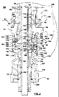
With reference to Figures 1, 2, and 3, a mold insert stack is shown that has
been configured in
accordance with a non-limiting embodiment of the present invention. The mold
insert stack 100 is for
use in an injection mold. The mold insert stack 100 includes a core assembly
108, a cavity insert 110,
and a split mold insert pair 140. The core assembly 108 includes a core insert
180, a support member
150, and a coupler member 160.
The core insert 180 includes a core body 181. An inner molding surface 185 is
defined on the core
body 181. In addition, a core-coupler interface 183 is defined on the core
body 181. The inner
molding surface 185 provides, in use, an inner portion of a molding cavity
that is shaped to mold a
preform.
The split mold insert pair 140 includes a complementary pair of split mold
inserts 140A and 140B.
The split mold insert pair 140 include a corresponding pair of split bodies
141. A split molding
surface 145 is defined on the pair of split bodies 141. The split molding
surface 145 defines a neck
finish portion of the molding cavity. A split-coupler interface 143 and a
split-cavity interface 149
are also defined on the pair of split bodies 141. A set of fastener interfaces
194 are also defined on the
pair of split bodies 141. Each fastener interface of the set of fastener
interfaces 194 are configured to
cooperate with a fastener, such as, for example, a cap screw, for securing the
split mold insert pair
140 to respective slides (not shown) of the injection mold.
The cavity insert 110 includes a cavity body 111. A cavity molding surface 115
and a cavity-insert
interface 133, at least in part, are defined on the cavity body 111. The
cavity molding surface 115
defines an outer portion of the molding cavity.
The support member 150 includes a support body 151. A support-sliding
interface 199 is defined on
the support body 151. A set of fastener interfaces 195 are also defined on the
support body 151. Each
fastener interface of the set of fastener interfaces 195 are configured to
cooperate with a fastener,
such as, for example, a cap screw, for securing the support member 150 to a
core plate (not shown) of
the injection mold.
4
CA 02712417 2010-07-15
WO 2009/103146 PCT/CA2009/000099
The coupler member 160 includes a coupler body 161. A coupler-core interface
173 and a coupler-
insert interface 163 are defined on the coupler body 161.
The mold insert stack 100 further includes a complementary sliding interface
198 that is defined on at
least one of the coupler body 161 and the core body 181.
The coupler-core interface 173 and the core-coupler interface 183 are
configured to cooperate, in
use, to mutually locate the coupler body 161 with the core body 181. The
coupler-insert interface 163
and the split-coupler interface 143 are configured to cooperate, in use, to
mutually locate the coupler
body 161 and the pair of split bodies 141. The split-cavity interface 149 and
the cavity-insert
interface 133 are configured to cooperate, in use, to mutually locate the pair
of split bodies 141 with
the cavity body 111. The support-sliding interface 199 and the complementary
sliding interface 198
are configured to cooperate, in use, to establish a slidable coupling that is
able to accommodate, in
use, a lateral move S I (Figure 2) between the support-sliding interface 199
and the complementary
sliding interface 198 and connect a load path (i.e. clamp tonnage) between the
support body 151 with
at least one of the core body 181 with the coupler body 161.
As shown with reference to Figure 1, the mold insert stack 100 may further
include a cavity retainer
130. The cavity retainer 130 includes a retainer body 131, the retainer body
131 configured to
cooperate, in use, with the cavity body 111 and a cavity plate (not shown) of
the injection mold for
retaining the cavity body 111 in the cavity plate. As shown with reference to
Figure 2, a further
portion of the cavity-insert interface 133 may be defined on the retainer body
131.
Also shown with reference to Figure 1, the mold insert stack 100 may further
include a gate insert
120. A portion of cavity molding surface 115 may be defined in a gate body of
the gate insert 120.
The gate insert 120 may also define an nozzle interface (not shown) for
receiving a nozzle (not
shown) of a molding material distribution system (e.g. hot runner).
As shown with reference to any one of Figures 2, or 3, the mold insert stack
100 may further include
a bubbler tube 190 for circulating a coolant fluid within a bore formed within
the core body 181.
As shown, the coupler body 161 may have an annular form that includes a collar
161A that projects
inwardly from an inner cylindrical surface 176 thereof. The coupler-core
interface 173 includes the
inner cylindrical surface 176 of the coupler body 161. The coupler-core
interface 173 may further
include a lower annular face 174 of the collar 161A that is between the inner
cylindrical surface 176
and an inside cylindrical surface 172 of the collar 161A.
5
CA 02712417 2010-07-15
WO 2009/103146 PCT/CA2009/000099
The core body 181 may have a cylindrical form that includes a flange 181A that
projects outwardly
from an outer cylindrical surface 189 thereof. The core-coupler interface 183
includes an outside
cylindrical surface 186 and a top annular face 184 of the flange 181A.
The coupler member 160 may include a retainer interface 166 that is defined
through the coupler
body 161 between an outer surface 152 of the coupler body 161 and the inner
cylindrical surface 176.
Likewise, a core-retainer interface 187 may be defined on the outside
cylindrical surface 186 of the
flange 181A. The retainer interface 166 is configured to cooperate, in use,
with a further interface 104
on a retainer 102 to releasably position a face 103 of the retainer 102 in a
securing configuration with
respect to the core-retainer interface 187, whereby the retainer 102 secures
the coupler member 160
with the core insert 180.
As shown with reference to Figure 1, a plurality of the retainer interface 166
are defined through the
coupler body 161, the plurality of the retainer interface 166 being arranged
in an angularly-spaced
relation around the coupler body 161. Likewise, a plurality of the core-
retainer interface 187 are
defined on the outside cylindrical surface 186 of the flange 181A. The
plurality of the core-retainer
interface 187 are arranged in the same angularly-spaced relation as the
plurality of the retainer
interface 166 for registering therewith.
As shown, the coupler-insert interface 163 may define a core lock for
receiving the split-coupler
interface 143 of the split mold insert pair 140. The core lock includes a top
annular face 171, a semi-
conical surface 162 of the coupler body 161, and an upper annular face 164 of
the collar 161A. The
semi-conical surface 162 inwardly diverges from the top annular face 171 to
define a female taper.
Also shown are the complementary surfaces 142, 144, 146 of the pair of split
bodies 141 that together
define the split-coupler interface 143 in the form of a complementary male
taper.
In accordance with another non-limiting embodiment, not shown, the coupler-
insert interface 163
may define a cavity lock (not shown) for receiving an alternative
configuration (not shown) of the
split-coupler interface of the split mold insert pair 140. The cavity lock
includes a top annular face, a
semi-conical surface, and an upper annular face (not shown) of the coupler
body 161 between the
semi-conical surface and an outer surface of the coupler body 161. The semi-
conical surface of the
coupler body 161 outwardly diverges from the top annular face 171 to define a
male taper.
The coupler body 161 may further define a coupler molding surface 175. The
coupler molding
surface 175 is defined between the upper annular face 164 and an inside
cylindrical surface 172 of the
6
CA 02712417 2010-07-15
WO 2009/103146 PCT/CA2009/000099
collar 161A. The coupler molding surface 175 provides, in use, a corner
portion of the molding cavity
that defines a portion of a top-sealing surface of the preform.
The coupler member 160 may also include an annular vent groove 169 that is
defined on the coupler
body 161 around a medial portion of an inside cylindrical surface 172 of the
collar 161A. The inside
cylindrical surface 172 is configured cooperate, in use, with an upper-outer
cylindrical surface 182 of
the core body 181 to define a vent gap therebetween. Further, a vent channel
168 may be defined
through the coupler body 161 between an outer surface 152 of the coupler body
161 and intersecting
with the annular vent groove 169.
The coupler member 160 may also include a nozzle 178 that is defined through
the coupler body 161
between the upper annular face 164 and intersecting with a coupler pressure
channel 179. The coupler
pressure channel 179 is defined through the coupler body 161 between a bottom
annular face 170 of
the coupler body 161 and intersecting with the nozzle 178 within the coupler
body 161.
As shown, the support body 151 may also have an tubular form. The support body
151 may further
include a support pressure channel 154 that is defined as a groove that passes
through both a portion
of a top annular surface 155 of the support body 151 and an inner
circumferential surface 156 of the
support body. 151. The support pressure channel 154 is configured to connect,
in use, an annular
pressure channel that is provided in a core clearance 107, that is defined
between the support body
151 and the core body 181, with the coupler pressure channel 179 of the
coupler member 160. The
annular pressure channel is in turn connectable to a source of compressed air
via a connecting
pressure channel 105. The connecting pressure channel 105 is defined through a
lower portion of the
support body 151. In operation, compressed air may be forced through the
nozzle 178 to assist with
ejection of the preform from the core insert 180.
The coupler member 160 may also include a coupler-alignment member interface
167 that is defined
in the coupler body 161 as a further cylindrical surface of a shallow bore
formed through the bottom
annular face 170. Likewise, the support body 151 may further include a support-
alignment member
interface 153 that is defined in the coupler body 161 as a cylindrical surface
of a shallow bore formed
through a top surface of the support body 151. The coupler-alignment member
interface 167 and the
support-alignment member interface 153 are configured to cooperate, in use,
with a complementary
interface of an outer cylindrical surface of an alignment pin. At least one of
the coupler-alignment
member interface 167 and the support-alignment member interface 153 may be
configured to provide
a gap in relation to the complementary interface. The gap may be selected to
provide a loose angular
alignment is established between the coupler member 160 and the support member
150 that is
7
CA 02712417 2010-07-15
WO 2009/103146 PCT/CA2009/000099
sufficient to align an inlet of the coupler pressure channel 179, on the
bottom annular face 170, with
the support pressure channel 154 of the support member 150. In addition, the
gap may be selected
such that it accommodates the lateral move S1, in use, between the support-
sliding interface 199 and
the complementary sliding interface 198.
The complementary sliding interface 198 may include a coupler-support
interface 177 that is defined
on the coupler body 161. The coupler-support interface 177 may include a
bottom annular face 170
of the coupler body 161. Likewise, the support-sliding interface 199 includes
a support-coupler
sliding interface 159. The support-coupler sliding interface 159 includes a
first portion of a top
annular surface 155 of the support body 151.
The complementary sliding interface 198 may alternatively, or additionally,
include a core-support
interface 196 that is defined on the core body 181. The core-support interface
196 may include a
bottom annular face 188 of the flange 181A. Likewise, the support-sliding
interface 199 includes a
support-core sliding interface 197. The support-core sliding interface 197
includes a second portion
of a top annular surface 155 of the support body 151.
The support body 151 may further include a compensating portion 158. The
compensating portion
158 is defined in the support body 151 and in the example being presented
herein comprises a conical
spring member, which in the cross section depicted in Figure 2 is a generally
S-shaped groove. The
compensating portion 158 is positioned in between the support-coupler sliding
interface 159 and a
bottom annular surface of the support body 151. Generally speaking, the
purpose of the compensating
portion 158 is to allow a degree of axial flexibility to the support body 151.
The degree of axial
flexibility allows to compensate for the mis-alignment of the mold inset stack
components.
Accordingly, the dimension of the compensating portion 158 is selected such
that to provide the
degree of flexibility to the support body 151, while providing operational
stability, while in use. For
the avoidance of doubt, the term "operational stability" as used herein above
and herein below is
meant to define an operational state between various components of the mold
insert stack 100 which
is suitable for proper operation of the mold insert stack 100, i.e. injection
of melt under pressure of
formation of the preform.
With the inclusion of the compensating portion 158, the core body 181 may be
further configured
such as to define a core-support interface 191. The core-support interface 191
may be formed on an
outer cylindrical surface 189 of a lower portion of the core body 181.
Likewise, a support-core
interface 106 may be defined on the support body 151. The support-core
interface 106 may be formed
on an inside circumferential surface of a lower portion of the support body
151. The core-support
8
CA 02712417 2010-07-15
PCT/CA2009/000099
July 2009 10-07-2009
H-7222-0-WO
interface 191 and the support-core interface 106 are also located beneath the
core clearance 107 that
is defined between the support body 151 and the core body 181. The core-
support interface 191 and
the support-core interface 106 are configured to cooperate, in use, to provide
a generally loose
alignment between the core body 181 and the support body 151. In executing the
foregoing a small
5 diametrical gap may be provided between the core-support interface 191 and
the support-core
interface 106.
As shown with reference to Figure 2, a shallow pocket 157 may be formed
through a bottom face of
the support body 151. The core assembly 108 further includes a retainer 200
that is received in a
10 complementary seat formed in the core body 181. In operation, a face of the
shallow pocket 157
cooperates with a face of a retainer 200 to retain the core body 181 within
the support body 151.
It can be said that a combination of the core clearance 107, the slidable
coupling and the
compensating portion 158 permits the core body 181 to move relative to the
support body 151 in a
direction depicted in Figure 2 as "Si" (i.e. lateral move) and a direction
"S2" (i.e. axial move). More
specifically, the core clearance 107 and/or the slidable coupling allows for
the lateral move and the
compensating portion 158 allows for the axial move.
Advantageously, the coupler body 161 may be formed of a first material with an
associated first
conditioning to impart to the coupler body 161 a first hardness value.
Likewise, the core body 181
may be formed of a second material with an associated second conditioning to
impart to the core
body 181 a second hardness value. Advantageously, the first hardness value
being less than the
second hardness value the coupler body 161 is forced to wear faster than the
core body 181. Whereby,
the coupler body 161 being a much simpler component to manufacture relative to
the core body 181,
and thus less expensive, may be more economically replaced.
In accordance with another non-limiting embodiment, not shown, the mold insert
stack 100 may be
configured as described hereinbefore but without the split mold insert pair
140. The mold insert stack,
so configured, would define a molding cavity for forming, by example, a
preform without a neck
finish. In such a mold insert stack the coupler member 160 may be configured
as described
hereinbefore with the exception that the coupler-insert interface 163 would be
configured to
cooperate with the cavity-insert interface 133 of the cavity insert 110.
Description ofthe embodiments of the present inventions provides examples of
the present invention,
and these examples do not limit the scope of the present invention. It is to
be expressly understood
that the scope of the present invention is limited by the claims. The concepts
described above may be
9
CA 02712417 2010-07-15
WO 2009/103146 PCT/CA2009/000099
adapted for specific conditions and/or functions, and may be further extended
to a variety of other
applications that are within the scope of the present invention. Having thus
described the
embodiments of the present invention, it will be apparent that modifications
and enhancements are
possible without departing from the concepts as described. Therefore, what is
to be protected by way
of letters patent are limited only by the scope of the following claims: