Note : Les descriptions sont présentées dans la langue officielle dans laquelle elles ont été soumises.
CA 02714158 2010-08-27
ELECTROSURGICAL GENERATOR
BACKGROUND
Technical Field
[0001] The present disclosure relates to an electrosurgical generator and,
more
particularly, to an electrosurgical generator including a fiber optic
correction circuit configured
to mitigate high and low frequency leakage currents associated with the
electrosurgical
generator.
Description of Related Art
[0002] Electrosurgical generators, e.g., radio frequency electrosurgical
generators,
configured for use in performing an electrosurgical procedure are well known
in the art.
Leakage currents, inadvertent currents between an electronic device and earth
ground, are a
serious concern in RF devices such as an RF electrosurgical
generator/electrode system.
Leakage currents may be attributed to low frequency leakage currents, which
may be associated
with the power source, patient leads and/or one or more outputs. Leakage
current may also be
attributed to high frequency leakage currents, such as, for example, bipolar
leakage current
and/or monopolar leakage current, each of which may be present at an energy
platform terminal
associated with an RF electrosurgical generator.
[0003] Methods for reducing and/or mitigating leakage currents are known in
the art.
More particularly, a method for mitigating leakage currents may include
providing one or more
isolation barriers in the form of an electrostatic shield at an RF output
module of an
electrosurgical generator. The RF output module may also include two
transformers coupled
together to form a coupling circuit that acts as an electrostatic shield. In
this instance, a relay
1
CA 02714158 2010-08-27
switch may be operatively connected to the RF output module and connected to a
second output
and/or load. The relay may include a contact shield enclosed in an earth
potential shield
associated with the RF electrosurgical generator.
[00041 Another method may include isolating the above relay by adding an opto-
isolated
barrier energized by one or more floating power supplies to the relay, which
effectively places
the relay on a patient side of the RF electrosurgical generator and eliminates
the need for
electrostatic shielding at the RF output module.
[00051 The disadvantages of the above-methods may include cost, transformer
and/or
relay efficiencies, size, and so on. In addition, in the instance where the
coupling circuit is used
as an electrostatic shield, the shield's own voltage represents an effective
opening in the shield.
This effective opening may cause unwanted electrical effects to neighboring
electrical circuits,
which, as can be appreciated by one skilled in the art, may cause the RF
electrosurgical generator
to function in a manner unintended by a user and/or manufacturer.
SUMMARY
[00061 The present disclosure provides an electrosurgical system. The
electrosurgical
system includes an electrosurgical generator adapted to supply electrosurgical
energy to tissue. A
power source operably couples to the electrosurgical generator and is
configured to deliver
power to one or more types of loads connected to the electrosurgical
generator. The
electrosurgical generator includes a controller including a microprocessor
coupled to the
electrosurgical generator and configured to control the output of the
electrosurgical generator. A
fiber optic connection circuit is in operative communication with the
controller and includes one
or more types of logic devices and one or more types of fiber optic channels.
The fiber optic
2
CA 02714158 2010-08-27
connection circuit is configured to mitigate leakage current associated with
at least one of a
plurality of components operatively associated with the electrosurgical
generator by providing
isolation.
[0007] In embodiments, the one or more types of logic devices is selected from
the group
consisting of a complex programmable logic device and a field programmable
gate array.
[0008] In embodiments, the one or more types of fiber optic channels is based
on a data link
protocol selected from the group consisting of at least Ethernet,
RS232/422/485, and S/PDIF.
[0009] In embodiments, the plurality of components associated with the
generator includes
one of a button and slider control; one of a port selection and relay control;
and one of a voltage
and current sensor.
[0010] In embodiments, the fiber optic connection circuit further includes one
or more
buffers operatively disposed between the controller and the logic device.
[0011] In embodiments, each of the voltage and current sensors is connected to
an RF output
module of the generator.
[0012] In embodiments, the controller is operatively disposed within the
electrosurgical
generator
[0013] The present disclosure provides an electrosurgical generator adapted to
supply
electrosurgical energy to tissue. The electrosurgical generator includes a
power source is
configured to deliver power to one or more types of loads connected to the
electrosurgical
generator. The electrosurgical generator includes a controller including a
microprocessor
coupled to the electrosurgical generator and configured to control the output
of the
electrosurgical generator. A fiber optic connection circuit is in operative
communication with
the controller and includes one or more types of logic devices and one or more
types of fiber
3
CA 02714158 2010-08-27
optic channels. The fiber optic connection circuit is configured to mitigate
leakage current
associated with at least one of a plurality of components operatively
associated with the
electrosurgical generator by providing isolation.
BRIEF DESCRIPTION OF THE DRAWING
[0014] Various embodiments of the present disclosure are described hereinbelow
with
references to the drawings, wherein:
[0015] Fig. IA is a schematic block diagram of a monopolar electrosurgical
system in
accordance with an embodiment of the present disclosure;
[0016] FIG. I B is a schematic block diagram of a bipolar electrosurgical
system in
accordance with another embodiment of the present disclosure;
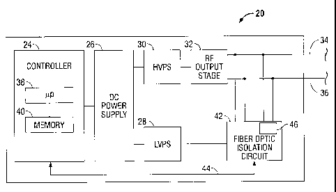
[0017] FIG. 2 is a schematic block diagram of a generator in accordance with
an
embodiment of the present disclosure; and
[0018] FIG. 3 is a schematic block diagram of specific components of the
generator of FIG.
2.
DETAILED DESCRIPTION
[0019] Particular embodiments of the present disclosure are described
hereinbelow with
reference to the accompanying drawings. In the following description, well-
known functions or
constructions are not described in detail to avoid obscuring the present
disclosure in unnecessary
detail.
[0020] The generator according to the present disclosure can perform monopolar
and bipolar
electrosurgical procedures, including vessel sealing procedures. The generator
may include a
4
CA 02714158 2010-08-27
plurality of outputs for interfacing with various electrosurgical instruments
(e.g., a monopolar
active electrode, return electrode, bipolar electrosurgical forceps,
footswitch, etc.). Further, the
generator includes electronic circuitry configured for generating radio
frequency power
specifically suited for various electrosurgical modes (e.g., cutting,
blending, division, etc.) and
procedures (e.g., monopolar, bipolar, vessel sealing).
[00211 As noted above, leakage current associated with RF generators may be
problem in
some instances. To reduce and/or mitigate leakage currents typically
associated with RF
generators, the generator of the present disclosure employs a fiber optic
connection circuit that is
operatively associated with a low voltage power supply of the generator. More
particularly, the
fiber optic connection circuit provides a primary fiber optic isolation
barrier at a RF amp output
module associated with a high voltage power supply side of the generator and
on the low voltage
power supply side of the generator.
[00221 FIG. IA is a schematic illustration of a monopolar electrosurgical
system I
configured for use with a generator 20 according to one embodiment of the
present disclosure.
The system 1 includes a monopolar electrosurgical instrument 2 having one or
more electrodes
for treating tissue of a patient P (e.g., electrosurgical cutting, ablation,
etc.). More particularly,
electrosurgical RF energy is supplied to the instrument 2 by the generator 20
via a supply line 4
that is connected to an active terminal 34 (FIG. 2) of the generator 20,
allowing the instrument 2
to coagulate, ablate and/or otherwise treat tissue. The energy is returned to
the generator 20
through a return electrode 6 via a return line 8 at a return terminal 36 (FIG.
2) of the generator
20. The active terminal 34 and the return terminal 36 are connectors
configured to interface with
plugs (not explicitly shown) of the instrument 2 and the return electrode 6,
which are disposed at
the ends of the supply line 4 and the return line 8, respectively.
CA 02714158 2010-08-27
[0023] Fig. lB is a schematic illustration of a bipolar electrosurgical system
3 configured for
use with the generator 20 according to the present disclosure. The system 3
includes a bipolar
electrosurgical forceps 10 having one or more electrodes for treating tissue
of a patient P. The
electrosurgical forceps 10 includes opposing jaw members 11 and 13 having an
active electrode
14 and a return electrode 16, respectively, disposed therein. The active
electrode 14 and the
return electrode 16 are connected to the generator 20 through cable 18, which
includes supply
and return lines 4, 8 coupled to the active and return terminals 34, 36,
respectively (FIG. 2). The
electrosurgical forceps 10 is coupled to the generator 20 at a connector 21
having connections to
the active and return terminals 34 and 36 (e.g., pins) plug disposed at the
end of the cable 18.
The connector 21 includes contacts from the supply and return lines 4, 8.
[0024] While the drawings depict an electrosurgical forceps 10 that is
suitable for use in
performing an open electrosurgical procedure, it is within the purview of the
present disclosure
that other types of electrosurgical forceps, e.g., electrosurgical forceps
suitable for use in
performing a endoscopic electrosurgical procedure, may be employed with the
generator 20.
[0025] The generator 20 includes suitable input controls (e.g., buttons,
activators, switches,
touch screen, etc.) for controlling the generator 20. In addition, the
generator 20 may include
one or more display screens for providing a user with variety of output
information (e.g.,
intensity settings, treatment complete indicators, etc.). The controls allow
the user to adjust
power of the RF energy, waveform parameters (e.g., crest factor, duty cycle,
etc.), and other
parameters to achieve the desired waveform suitable for a particular task
(e.g., coagulating,
tissue sealing, intensity setting, etc.).
[0026] FIG. 2 shows a schematic block diagram of the generator 20 having a
controller 24
and DC power supply 26. The DC power supply 26 is connected to a conventional
AC source
6
CA 02714158 2010-08-27
(e.g., electrical wall outlet) and includes a low voltage power supply 28
("LVPS") and a high
voltage power supply 30 ("HVPS"). The HVPS 30 provides high voltage DC power
to an RF
output stage 32, e.g., an RF amp module 32, which then converts high voltage
DC power into RF
energy and delivers the RF energy to the active terminal 34. The energy is
returned thereto via
the return terminal 36. The LVPS 29 provides power to various components of
the generator
(e.g., input controls, displays, etc.), as will be discussed in further detail
below. Each of the
HVPS and LVPS may include one or more DC-DC converters 68 configured to
increase or
decrease the power supplied by the DC power supply 26. In embodiments, the
generator 20
may include one or more power factor connection (PFC) modules 64 serving as
boost regulators
and in operative communication with each of the HVPS and LVPS. The PFC module
64 serves
to improve the power factor of the generator 20 and regulate the incoming line
voltage to a
constant. With this purpose in mind, the PFC module 64 may include any number
of capacitors,
contactors, and/or inductors
[0027] The generator 20 may include a plurality of connectors to accommodate
various types
of electrosurgical instruments (e.g., electrosurgical surgical instrument 2,
electrosurgical forceps
10, etc.). Further, the generator 20 may be configured to operate in a variety
of modes such as
ablation, monopolar and bipolar cutting, coagulation, etc. The generator 20
may also include a
switching mechanism (e.g., relays) to switch the supply of RF energy between
the connectors,
such that, for example, when the instrument 2 is connected to the generator
20, only the
monopolar plug receives RF energy.
[0028] The controller 24 includes a microprocessor 38 operably connected to a
memory 40,
which may be volatile type memory (e.g., RAM) and/or non-volatile type memory
(e.g., flash
media, disk media, etc.). The microprocessor 38 includes an output port that
is operably
7
CA 02714158 2010-08-27
connected to the DC power supply 26 and/or RF output stage 32 allowing the
microprocessor 38
to control the output of the generator 20 according to either open and/or
closed control loop
schemes. Those skilled in the art will appreciate that the microprocessor 38
may be substituted
by any logic processor (e.g., control circuit) adapted to perform the
calculations discussed herein.
[0029] With reference to FIGS. 2 and 3, a fiber optic connection circuit 42
(connection
circuit 42) is configured to reduce or mitigate leakage current associated
with one or more
components (e.g., voltage and/or current sensors, buttons and/or slider
controls, port selection
and/or relay controls) associated with the generator 20. With this purpose in
mind, the
connection circuit 42 is powered by the LVPS and is in operative communication
with the
controller 24. The connection circuit 42 includes one or more fiber optic
channels 44 and one or
more logic devices 46.
[0030] Logic device 46 may be any suitable logic device. In the embodiment
illustrated in
FIG. 3, the logic device 46 a programmable array logic (PAL) device. In
embodiments, the PAL
device may be selected from the group consisting of a complex programmable
logic device
(CPLD) and a field programmable gate array (FPGA) device. In certain
embodiments, the logic
device 46 may include a combination of the CPLD and FPGA device. The specific
configuration
logic device 46 may vary based on the ultimate needs of a user. For example,
the FPGA device
may be employed when a high degree of accuracy is required in monitoring
and/or measuring the
power output of the generator 20. In an embodiment, the FPGA may include a
processor core.
Conversely, the CPLD may be employed when a high degree of accuracy is not
required in
monitoring and/or measuring the power output of the generator 20.
[0031] Logic device 46 is powered by the DC power supply 26 via a DC-DC
converter 68
that is operatively disposed on the LVPS side of the generator 20. Logic
device 46 may be in
8
CA 02714158 2010-08-27
operative communication with one or more components associated with the LVPS
28. More
particularly, one or more of the pins associated with the logic device 46
connects to one or more
voltage and current sensors 50, button and slider controls 52 and/or port
selection and relay
controls 54 of the generator 20 (FIG. 3). A pin of the logic device 46 is
connected to a signal
ground 56. Each of the voltage and current sensors connects to the active and
return terminals 34
and 36, respectively.
[00321 Fiber optic channel 44 provides a bi-directional data link to the
controller 24. The
fiber optic channel 44 may be based on any suitable data link protocol
including but not limited
to Ethernet, RS232/422/485, Sony/Philips Digital Interconnect Format (more
commonly known
as S/PDIF), etc. In the embodiment illustrated in FIG. 3 the fiber optic
channel 44 is in the form
of an Ethernet cable 58 and provides a data link between the logic device 46
and the controller
24. In the embodiment illustrated in FIG. 3, a second FPGA 62 that is coupled
to chassis ground
66 is operatively associated with the controller 24 and serves as an
intermediate interface
between the controller 24 and fiber optic channel 44. In an embodiment, the
second FPGA 62
may include a processor core (e.g., a digital signal processor, "DSP"), or may
be replaced by a
CPLD. One or more transmit and receive buffers (collectively referred to as
buffers 60) is used
to regulate the flow of data frames between the microprocessor 39 and logic
array 46. As can be
appreciated by one skilled in the art, increasing the number of buffers 60
between the logic
device 46 and the second FPGA 62, microprocessor 38 and/or controller 24
improves overall
generator performance during periods of heavy data transmission traffic
between the logic device
46 and the second FPGA 62, microprocessor 38 and/or controller 24.
9
CA 02714158 2010-08-27
[0033] In an embodiment, it may prove useful to isolate an input side of the
RF amp module
32. In this instance, the HVPS 30 may include a DC-DC converter 70 that is
operatively
connected to a PFC module serving as a boost regulator (FIG. 3).
[0034] In use, the fiber optic connection circuit 42 provides an isolation
barrier on the low
voltage power supply side of the generator 20 and, more particularly, on a low
voltage digital
side associated with the generator 20. The fiber optic channel 44 of the fiber
optic connection
circuit 42 provides an ideal transmitting medium for either high or low
voltage measurements.
In addition, the fiber optic connection circuit 42 and integral components
associated therewith
are configured to provide electrical isolation from the HVPS, e.g., RF output
stage and
electromagnetic interference (EMI) associated therewith; this EMI may be
present while the fiber
optic connection circuit 42 is measuring and/or monitoring voltage and
currents associated with
one or more components of the generator 20. However, because of the dielectric
nature of
optical fibers, connection circuit 42 and integral components associated
therewith are immune to
the EMI. That is, since the optical fiber in the fiber optic channel 44 has no
metallic
components, the fiber optic channel 44 can be installed in areas with EMI,
including radio
frequency interference (RFI).
[0035] While several embodiments of the disclosure are shown in the drawings
and/or
discussed herein, it is not intended that the disclosure be limited thereto,
as it is intended that the
disclosure be as broad in scope as the art will allow and that the
specification be read likewise.
Therefore, the above description should not be construed as limiting, but
merely as
exemplifications of particular embodiments. Those skilled in the art will
envision other
modifications within the scope and spirit of the claims appended hereto.