Note : Les descriptions sont présentées dans la langue officielle dans laquelle elles ont été soumises.
CA 02714450 2010-08-06
WO 2009/099515
PCT/US2009/000339
Meter Socket Assembly With Interchangeable Meter Jaw Assembly
Field
This invention relates to a watt-hour meter socket device or modular (group)
metering devices. In particular, this invention relates to a meter socket
assembly
having an interchangeable meter jaw assembly for use with a watt-hour meter.
Background
Socket type electrical watt-hour meters are used to measure and indicate the
amount of electrical power consumption in a residence, industry or business.
Typically, a socket type watt-hour meter plugs into a meter socket using a
blade-like
stab or meter blade connector located on the watt-hour meter. The meter socket
itself
is mounted inside a meter base or a panel. A meter socket commonly has a
spring
loaded receptacle-like jaw to receive and contact the watt-hour meter blade
insertion.
The meter jaw and spring provide enough force to press meter blade and conduct
electricity while maintaining a certain current load and a heat rise.
The line side of a meter socket is connected to the utility electrical power
source, while the load side of a meter socket is connected to the tenant. A
watt-hour
meter is inserted onto the meter jaws on a meter socket to bridge the line and
load
making the electrical connection between the utility power source and the
tenant. In
the industry, spring tempered copper meter jaws are mounted on meter sockets
to
receive plug-in watt-hour meters. Due to limited spacing and special
application, the
meter jaws carry high current density and have less contact surface area.
Therefore,
the contact surface may be weak for electrical connection between a meter jaw
and a
watt-hour meter blade, a meter jaw and its mount connector, and a meter jaw
itself.
This is evident in modular metering devices, which have heavier line and load
buses
and stronger bounding bus connections. Such weak positions with electrical
connection make the components of meter jaw assemblies prone to damage during
a
power surge or electrical interruption. From a time saving perspective, it
would be
more beneficial to be able to change an individual front removable and
replaceable
meter jaw assembly on a meter socket or even replace a whole meter socket in
modular metering devices whenever a meter jaw assembly or a meter socket is
damaged, rather than replacing the whole meter box device.
1
CA 02714450 2013-09-25
54106-570
Meter jaw alignment is another factor that affects meter socket performance
conducting electricity. Meter jaw misalignment is caused by tolerance built-up
in multiple
components in fabrication and during the assembly process. In the field, meter
jaw
misalignment may cause service and reliability issues. A meter socket with
misaligned meter
jaws or meter jaw assemblies make installing a watt-hour meter more difficult.
There will be
connection issues for conduction of electricity. For example, a twisted,
deformed or even
damaged meter jaw may cause extensive heat on meter jaws.
Therefore there is a need for improvement in meter sockets and in particular
meter jaw assemblies.
There is also a need to provide a robust meter socket base to assist precise
meter jaw alignment with their mounting plates.
Summary
In accordance with an aspect of this invention, a meter socket device for an
electrical meter box is provided comprising: a meter socket base; and at least
one
interchangeable meter jaw assembly wherein the meter jaw assembly locks into
the meter
socket base fastenerless.
According to another aspect of the present invention, there is provided a
meter
socket device for an electrical meter box comprising: a meter socket base,
comprising a cross
locking tab; and at least one interchangeable meter jaw assembly, comprising a
meter jaw
mounting plate, wherein the meter jaw assembly locks into the meter socket
base; wherein the
cross locking tab fastens and holds an end of the meter jaw mounting plate.
In accordance with another aspect of this invention, an interchangeable meter
jaw assembly for an electrical meter box comprising: a mounting plate; a meter
jaw for
contacting a meter blade of a watt hour meter fastened to the mounting plate;
and an
insulating guide attached to the meter jaw for protection from contact.
2
CA 02714450 2015-09-09
54106-570
In accordance with another aspect of this invention, a method of retaining at
least one interchangeable meter jaw assembly on a meter socket base in an
electrical meter
box, the steps comprising: providing an interchangeable meter jaw assembly;
providing a
meter socket base with at least one receiving slot wherein the receiving slot
includes means
for receiving and locking the interchangeable meter jaw assembly fastenerless;
sliding the
interchangeable meter jaw assembly to stop position; and fastening the
mounting plate to an
electric connect.
In accordance with another aspect of this invention, a method of interchanging
meter jaws, the steps comprising: loosening a fastener of a mounting plate;
pressing a cross
locking tab; and sliding a meter jaw assembly out.
In accordance with another aspect of this invention, a method of meter jaw
alignment in an electrical meter box, the steps comprising: providing a meter
jaw; providing a
meter jaw mounting plate; affixing meter jaw to meter jaw mounting plate;
affixing meter jaw
mounting plate to a meter socket base; providing a mounting plate wherein the
mounting plate
is shaped to be locked in position for supported meter jaw and keeping jaw
alignment; and
providing mounting plate with means for centering.
According to one aspect of the present invention, there is provided a meter
socket device for an electrical meter box comprising: a meter socket base,
comprising a
receiving slot and a cross locking tab; and at least one interchangeable meter
jaw assembly,
comprising a meter jaw mounting plate; wherein while the cross locking tab is
pressed down,
the meter jaw assembly slides in under holding pads of the receiving slot and
against a close
end of the receiving slot, such that an end surface of the meter jaw mounting
plate passes the
cross locking tab, then the cross locking tab rebounds back and blocks on the
end surface of
the meter jaw mounting plate from moving back.
According to another aspect of the present invention, there is provided a
method of retaining at least one interchangeable meter jaw assembly on a meter
socket base in
an electrical meter box, the steps comprising: providing an interchangeable
meter jaw
assembly with a meter jaw mounting plate; providing a meter socket base with
at least one
receiving slot and a cross locking tab; while the cross locking tab is pressed
down, sliding the
3
CA 02714450 2015-09-09
54106-570
meter jaw assembly under holding pads of the receiving slot and against a
close end of the
receiving slot, such that an end surface of the meter jaw mounting plate
passes the cross
locking tab, then the cross locking tab rebounds back and blocks on the end
surface of the
meter jaw mounting plate from moving back; and fastening the meter jaw
mounting plate to
an electric connect.
According to still another aspect of the present invention, there is provided
a
method of meter jaw alignment in an electrical meter box, the steps
comprising: providing a
meter jaw; providing a meter jaw mounting plate; affixing the meter jaw to the
meter jaw
mounting plate; and affixing the meter jaw mounting plate to a meter socket
base which
comprises a receiving slot and a cross locking tab; wherein the meter jaw
mounting plate is
shaped to be locked in position for supporting the meter jaw and keeping the
meter jaw
alignment; the meter jaw mounting plate has means for centering; and while the
cross locking
tab is pressed down, sliding the meter jaw assembly under holding pads of the
receiving slot
and against a close end of the receiving slot, such that an end surface of the
meter jaw
mounting plate passes the cross locking tab, then the cross locking tab
rebounds back and
blocks on the end surface of the meter jaw mounting plate from moving back.
One object of some embodiments of this invention is to provide a robust meter
socket with individually front removable and replaceable meter jaw assemblies
and
5th terminal provision.
Another of the objects of some embodiments is to provide a meter socket base
on which meter jaw assemblies are able to be easily replaced and retained.
A further object of some embodiments is to provide a meter socket with built
in features for precise meter jaw alignment.
Detailed Description
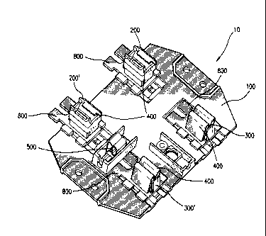
FIG. 1 shows a meter socket device 10 as described in this invention. The
meter socket device 10 comprises a meter socket base 100, a pair of line meter
jaw assemblies
200 and 200', a pair of load meter jaw assemblies 300 and 300', and an
optional 5th terminal
assembly 500. The line meter jaw assemblies 200/200' & the
3a
CA 02714450 2010-08-06
WO 2009/099515
PCT/US2009/000339
load meter jaw assemblies 300/300' are collectively called the meter jaw
assemblies
400. The meter jaw assemblies 400 are installed and removed from the meter
socket
base 100 by simply releasing the cross locking tab 600 shown in FIG 7 located
on the
meter socket base 100. The cross locking tab 600 fastens & holds the end of
the meter
jaw mounting plate 800 of the meter jaw assemblies 400. This will be described
further in FIG 6.
FIG 2 shows an alternative embodiment of meter socket assembly 10 with a
horn by-pass installed. The horn by-passes are installed on load meter jaw
assemblies
300H and 300H', while the horn by-passes are installed separately on the meter
jaw
mounting plates 800 of the line jaw assemblies 200 and 200' of the meter
socket
assembly. The line and load horn by-passes, optional for ringless type
metering
devices, are connect to a manual by-pass cable which will by-pass a watt-hour
meter.
A horn by pass is used in cases where electrical power has to be supplied
continuously when the watt-hour meter is to be removed for maintenances or
upgrades, for example, an emergency room or a situation where medical
conditions
demand continuous electrical power.
FIG 3 shows a ring type modular metering device 1000 that has the meter
socket assemblies 10 installed. The meter socket assemblies 10 are mounted
inside the
enclosure 1020 and covered by meter covers 1010, while the center of the meter
cover
align with the center of the meter socket device 10 so that a watt-hour meter
(not
shown but standard in the art) may be installed onto the meter socket assembly
10
through a meter cover opening. The meter cover 1010 and protective cardboard
cover
1100 were blanked in order to see the interior components. The meter socket
assembly 10 is mounted to the enclosure 1020 on a pair of mounting brackets
1030
with fasteners 1040. The line meter jaw assembly 200/200' is connected to a
riser bus
1200/1200'. The riser bus 1200/1200' links to the line electrical power,
through the
line strap 1300/1300" joined with a fastener 1400. The load meter jaw assembly
300/300' is connected to load strap (not shown but standard in the art), which
leads to
load tenant, by a fastener 1400. Therefore, whenever a line meter jaw assembly
200/200' or a load meter jaw assembly 300/300' needs to be replaced, only one
fastener 1400 needs to be loosened to retrieve the line meter jaw assembly
200/200'
or the load meter jaw assembly 300/300'. Once a new line meter jaw assembly
200/200' or a load meter jaw assembly 300/300' has been installed, the
appropriate
fastener 1400 must be tightened to a specified torque to complete
installation.
4
CA 02714450 2010-08-06
WO 2009/099515
PCT/US2009/000339
FIG 4 a) is an enlarged view of an insulating meter jaw guide 1600 that may
be fastened onto either the line meter jaw assembly 200/200' or the load meter
jaw
assembly 300/300' to provide protection from accidental contact.
FIG 4 b) shows an enlarged view of a line meter jaw assembly 200/200' or a
load meter jaw assembly 300/300'. The meter jaw 1700, the metal meter jaw
spring
guide 700 and the meter jaw mounting plate 800 are assembled together with a
fastener from the bottom of the meter jaw mounting plate 800 (not shown due to
the
orientation of the view). The special shape of the meter jaw mounting plate
800 is
designed to fit in the meter socket base 100 and to be locked in position for
supporting
meter jaw 1700 and keeping jaw alignment.
FIG 5 shows the detail of the meter jaw mounting plate 800. In the line meter
jaw assembly 200/200' or the load meter jaw assembly 300/300', a meter jaw
1700
stands on the top surface 810 of the meter jaw mounting plate 800 and is
mounted
through the aperture 820. The halfshear (or emboss) 830 on the top surface 810
fits
into a slot at the bottom of a meter jaw 1700 to guide the center line of the
meter jaw
1700 aligning it with the center line of the meter jaw mounting plate 800. The
first
side slots 840/840' and the second side slots 850/850' are precisely
fabricated to fit in
the holding pads 2200 shown in FIG 7 and mate with the side guide features
2400 in
order to control the alignment of either the line meter jaw assembly 200/200'
or the
load meter jaw assembly 300/300'. The first extended fins 860/860' and the
second
extended fins 870/870' inserted into the holding slots 2500 in FIG 7 of a
meter jaw
pocket 2100(see FIG 6). The first end surfaces 880/880' and second end
surfaces
890/890' of the first and second extended fins 860/860' ;870/870' respectively
are
directly against the close ends 2600 of the meter jaw assembly holding slots
2500
(shown in FIG 7) when one of meter jaw assemblies 400 is installed. The cross
locking tab 600 in FIG 7 will lock the end surface 900 of the meter jaw
mounting
plate 800. The open "U" shaped slot 910 is to receive a fastener 1400 as shown
in FIG
3 from the connection bus to build electrical connection, and allows one of
the meter
jaw assemblies 400 to slide off from the opening end of the slot 910 by
loosening the
fastener 1400 whenever one of meter jaw assemblies 400 needs to be replaced.
FIG 6 shows the meter socket base 100. The mounting area 1800 surrounded
by barreling wall 1900 mount to enclosure 1020 and ring type meter covers 1010
in
FIG 3 or ringless meter support bracket (not shown). Four mounting holes 2000
are
CA 02714450 2010-08-06
WO 2009/099515
PCT/US2009/000339
provided for robust and firm joint to withstand the force of the insertion and
extraction of a watt-hour meter. There are four receiving slots 2100 for
receiving line
meter jaw assemblies 200/200' or load meter jaw assemblies 300/300' in a meter
socket assembly 10. Six o'clock position 5th terminal 2100 and nine o'clock
position
5th terminal 2200 provisions are provided for alternative 5th terminal
connection.
FIG 7 shows a detailed view of receiving slot 2100 for one of meter jaw
assemblies 400. When installing one of meter jaw assemblies 400 to the meter
socket
base 100, one of meter jaw assemblies 400 is fitted in between the holding
pads 2200
and laid on the sliding platform 2300/2300' with the guiding features 2400
directly
against the first and second slots 840/840';850/850' on the meter jaw mounting
plate
800. The tolerance between the guiding features 2400 is tight so that the
clearances
between the guiding features 2400 and the first and second slots
840/840';850/850' on
the meter jaw mounting plate 800 are precisely controlled. This enables one of
the
meter jaw assemblies 400 to slide by and prevents a meter jaw assembly 400
from
rattling. While the cross locking tab 600 is pressed down, a meter jaw
assembly 400
may slide in under the holding pads 2200 and against the close end 2600. The
end
surface 900 of the meter jaw mounting plate 800 passes the cross locking tab
600,
then the cross locking tab 600 rebounds back and blocks on the end surface 900
of a
meter jaw assembly 400 from moving back. The cross locking tab 600 includes
three
portions: the flex link 610, the locking pad 620, and the extension 640. The
flex link
610, rooted on the back side of the sliding platform 112/112', is a thin
stripe of a
diagonal bridge 630/2300 that extends to the middle of the receiving slot
2100. The
top surface of the locking pad 620 is above the surface of the sliding
platform
2300/2300' to block the end surface 900 of the meter jaw mounting plate 800
when a
meter jaw assembly 400 is installed. The slot 630 on the locking pad 620
allows a
screw driver or the like to press down on the cross locking tab 600 for
releasing an
assembled meter jaw assembly 400. The extension 640 paired with stop tab 2900
is a
protection feature that prevents the cross locking tab 600 from over travel
and damage
when the locking pad 620 is pressed to release an installed meter jaw
assembly400.
Between the end walls 2700 and the top of the supporting link 2800, the open
= receiving slot is to clear the sliding path for installing and removing a
meter jaw
assembly 400. The supporting link 2800 also links the opening end of the open
receiving slot to strengthen the meter socket base 100.
6
CA 02714450 2014-12-17
54106-570
While the foregoing description and drawings represent the preferred
embodiments of the present invention, it will be apparent to those skilled in
the art
that various changes and modifications may be made therein without departing
from
the scope of the present invention.
=
7