Note : Les descriptions sont présentées dans la langue officielle dans laquelle elles ont été soumises.
CA 02718368 2010-09-10
WO 2009/112955 PCT/IB2009/005678
1
MODULAR IMAGING SYSTEM WITH WIRELESS
TRANSMISSION AND LOCKING CONNECTOR
BACKGROUND OF THE INVENTION
The present invention relates to a modular imaging system in which a camera
and
separate display can be used in a mobile application, and more particularly,
is directed to
additional modules for wireless communication and a locking connector.
In environments such as police or military work, it is often desirable to see
what is
inside a building, vehicle or other remote viewing environment, without
putting a person in
direct line of fire from any occupant of the building or vehicle. Several
vendors provide
equipment kits for this purpose. Typically the kit includes one or more
cameras, an
extension pole for the camera and a display to show what the camera sees.
Roughly, a
modular imaging kit can cost around $50,000.
Figs. lA-lH are block diagrams of modules of an imaging system available from
Zistos Corporation, Holbrook, NY, www.zistos.com, and Figs. 2A-2C show the
components
of Figs. 1 A-1 G arranged in exemplary use configurations.
Fig. IA shows camera 10 having interface 11. Camera 10 may be a black and
white
camera, a color camera, or other suitable camera. Interface 11 provides power
to the camera,
and supplies a video signal from the camera. Interface 11 includes a threaded
locking collar
for mating camera 10 to another module.
Fig. lB shows extension pole 20 having interface 21 and articulating section
23 at
one end and interface 22 at an opposite end. Extension pole 20 has generally
concentrically
arranged tubes in a wedding cake shape that can be extended to form a long
pole, such as 14
feet, and retracted for ease of carrying to a length of about 3 feet. When
extended, the tubes
are secured by screwing threaded mechanisms (not shown); the mechanisms are
unscrewed
to permit the tubes to be collapsed for carrying. Articulating section 23 has
a segmented
gooseneck to enable positioning of a to-be-attached camera in three
dimensions. Interfaces
21 and 22 are similar to interface 11.
Fig. 1C shows cable 25 having interfaces 26 and 27 at each end. Cable 25
encloses
power and video lines, typically in waterproof form. Interfaces 26 and 27 are
similar to
interface 11.
CA 02718368 2010-09-10
WO 2009/112955 PCT/IB2009/005678
2
Fig. 1D shows display 30 having interface 31 and enclosed power receptacle 32.
Interface 31 is similar to interface 11. Power receptacle 32 is generally a
cavity with
connectors, for receiving a battery or set of batteries. Display 30 is often
worn on a person's
body, such as on the chest, for ease of viewing by the wearer. In other cases,
display 30 may
be carried in a person's hands.
Fig. IE shows battery 33 for use in power receptacle 32. Battery 32 may be,
for
example, nickel metal hydride (NiMH) batteries.
Fig. 2A shows a first exemplary configuration. Camera 10 is connected to
extension
pole 20, which is connected to cable 25, which is connected to display 30
having battery 33
installed therein. Generally, one person holds extension pole 20 to position
camera 10 in a
desired spot, and views display 30 to see the interior of a building or
vehicle, or the
underside of a vehicle, and so on. Whatever is seen by camera 10 appears on
display 30, in
real time.
Fig. 2B shows a second exemplary configuration. Camera 10 is connected to
cable
25 which is connected to display 30. This configuration is useful, for
example, when a
person crouches under a window ledge, holds the camera over the ledge, and
views what is
inside a room without being visible to the occupants of the room. Another
situation in which
an imaging system is useful is when it is dropped down a shaft to look for
hidden material
such as drugs or explosives. Whatever is seen by camera 10 appears on display
30, in real
time.
The Zistos imaging system includes wireless capability, generally for people
in
different locations to be viewing separate displays showing the same video.
Figs. 1F-1H
show the wireless components of the Zistos system, and Fig. 2C shows an
exemplary
wireless configuration.
Fig. 1F shows a display with wireless transmission of what is being viewed to
another location. Display 40 has interface 41 and enclosed power receptacle
42. Interface
41 is similar to interface 11. Power receptacle 42 is generally a cavity with
connectors, for
receiving a battery or set of batteries. Display 40 is often worn on a
person's body, such as
on the chest, for ease of viewing by the wearer. In other cases, display 40
may be carried in
a person's hands. The signal provided to display 40 is also provided to
transmitter 43, for
wireless transmission on an antenna at a channel frequency selected by channel
selection
CA 02718368 2010-09-10
WO 2009/112955 PCT/IB2009/005678
3
knob 44. Typically frequencies include 900 Mhz and 2.4 GHz. Transmitter 43
takes a
baseband video signal and modulates the selected channel frequency to provide
a wireless
signal.
Fig. 1G shows wireless receiver module 50 having an antenna providing a signal
to
receiver 51 that operates at a channel frequency selected by channel selection
knob 52.
Receiver 51 receives a wireless signal and demodulates it to provide a
baseband video signal
which is then supplied via cable 53 to interface 54. Interface 54 is similar
to interface 11.
Fig. 1H shows receiver base station 60 having cathode ray tube (CRT) 63, and
which
must be used indoors and attached to an AC power supply. Base station 60 has
an antenna
providing a signal to receiver 61 that operates at a channel frequency
selected by channel
selection knob 62. Receiver 61 receives a wireless signal and demodulates it
to provide a
baseband video signal for display on CRT 63.
Fig. 2C shows an exemplary wireless configuration. Camera 10 is connected to
cable
25 which is connected to display 40. The video signal shown on display 40 is
wireless
transmitted to receiver module 50, which then, via cable 53, provides the
video signal to
display 30. An instance of use is where a person having camera 10 is searching
houses,
while a protected person, such as an expert, is in another location viewing on
display 30
what the searcher is searching.
Other manufacturers of modular imaging systems include Tactical Electronics &
Military Supply, LLC, Broken Arrow, OK, www.tacticalelectronics.com, and
Search
Systems Incorporated, Bakersfield, CA, www.searchsystems.com.
There is, however, an on-going need for an improved imaging system providing
more flexibility to users.
SUMMARY OF THE INVENTION
In accordance with an aspect of this invention, there is provided a modular
imaging
system, comprising a camera module having a camera and an electrical interface
for
providing a video signal representing an image picked up by the camera, a
wireless
transmitter module having an electrical interface for receiving the video
signal from the
camera module and generating a high frequency signal, a wireless receiver
module for
receiving the high frequency signal from the wireless transmitter module and
producing a
CA 02718368 2010-09-10
WO 2009/112955 PCT/IB2009/005678
4
baseband signal, and a display module for receiving the baseband signal and
displaying the
baseband signal on a display.
In accordance with another aspect of this invention, there is provided a
secondary
interlock mechanism, comprising: a U-shaped collar having eccentrically shaped
holes and a
depression for receiving a spring, and a module having alignment pin
receptacles for
receiving alignment pins having radial channels, and having the U-shaped
collar inserted
into the module and the spring so that the eccentrically shaped holes engage
with the radial
channels on the alignment pins to restrain the alignment pins from moving due
to the force
exerted on the U-shaped collar from the spring.
It is not intended that the invention be summarized here in its entirety.
Rather,
further features, aspects and advantages of the invention are set forth in or
are apparent from
the following description and drawings.
BRIEF DESCRIPTION OF THE DRAWINGS
Figs. IA- I H are block diagrams of modules of a known imaging system;
Figs. 2A-2C show the components of Figs. lA-1H arranged in exemplary use
configurations;
Figs. 3A-31 are block diagrams of modules of another known imaging system;
Figs. 4A-4J are three-dimensional views of different camera modules;
Figs. 5A-5B are three-dimensional views of an articulating module;
Figs. 5C-5D are three-dimensional views of an articulating module connected to
a
camera module;
Figs. 6A-6B are three-dimensional views of a pistol grip module;
Fig. 6C is a three-dimensional view of a pistol grip module connected to a
camera
module;
Figs. 7A-7E are views relating to an extension pole;
Figs. 8A-8B are three-dimensional views of a display module;
Figs. 9A-9B are three-dimensional views of a battery module;
Figs. 9C-9D are three-dimensional views of a display module connected to a
battery
module;
Figs. 10A-10B show the components of Figs. 3A-3I arranged in exemplary use
configurations;
CA 02718368 2010-09-10
WO 2009/112955 PCT/IB2009/005678
Figs. 11A-11I are block diagrams of components for wireless transmission in a
modular imaging system in accordance with the present invention;
Figs. 12A-12B are three-dimensional views of a wireless transmitter module;
Figs. 13A-13B are three-dimensional views of a wireless receiver module;
Figs. 14A-14B are three-dimensional views of a compact battery;
Figs. 14C-14D are three-dimensional views of a wireless transmitter module
connected to a compact battery;
Figs. 15A-15B are three-dimensional views of a first wireless interface
module;
Figs. 16A-16D are three-dimensional views of an accessory tray;
Fig. 16E is a three-dimensional view of an accessory tray connected to a
display
module;
Figs. 16F-16G are three-dimensional views of an accessory tray connected to a
wireless receiver module;
Fig. 16H is a three-dimensional view of an accessory tray connected to a
display
module and a wireless receiver module;
Figs. 17A-17B are three-dimensional views of a tripod;
Figs. 18A-18H are block diagrams showing the components of Figs. 3A-31 and 11
A-
111 arranged in exemplary transmit configurations;
Figs. 181-18K are block diagrams showing the components of Figs. 3A-3F and l0A-
101 arranged in exemplary receive configurations; and
Figs. 19A-19H are diagrams referenced in explaining a spring-loaded locking
mechanism, used as a secondary interlocking mechanism.
DETAILED DESCRIPTION
A modular imaging system includes a camera module having a camera and an
electrical interface for providing a video signal representing an image picked
up by the
camera, a wireless transmitter module having an electrical interface for
receiving the video
signal from the camera module and generating a high frequency signal, a
wireless receiver
module for receiving the high frequency signal from the wireless transmitter
module and
producing a baseband signal, and a display module for receiving the baseband
signal and
displaying the baseband signal on a display. A secondary interlock mechanism
includes a U-
shaped collar having eccentrically shaped holes and a depression for receiving
a spring, and
CA 02718368 2010-09-10
WO 2009/112955 PCT/IB2009/005678
6
a module having alignment pin receptacles for receiving alignment pins having
radial
channels, and having the U-shaped collar inserted into the module and the
spring so that the
eccentrically shaped holes engage with the radial channels on the alignment
pins to restrain
the alignment pins from moving due to the force exerted on the U-shaped collar
from the
spring.
Wireless transmit and receive modules for a modular imaging system are
provided,
each having mechanical connectors with a secondary interlock for a more secure
fit to other
modules. The secondary interlock provides a quick release mechanism, and has
no threads
to gather dust, dirt or sand. Additionally, the wireless transmit and receive
modules each
have two sets of mechanical connectors to maximize compatibility with existing
modules of
the modular imaging system. The secondary interlock mechanism is also employed
on other
modules of the modular imaging system.
Typical military and civilian mission environments for a modular imaging
system are
search and rescue (SAR), combat, force protection and interdiction. SAR
includes
site/safety monitoring, water rescue, confined space entry, building collapse
and fire.
Combat includes hostage rescue, building or confined space clearing, sniper
observer aid,
and covert/tactical surveillance. Force protection includes evidence recovery,
explosive
ordinance disposal (EOD) sweeps, perimeter/gate security vehicle search,
intruder detection
and surveillance. Interdiction includes covert surveillance, stowaway/fugitive
detection,
contraband weapons or other restricted materials searches, and counter-drug
operations.
Another known modular imaging system will now be described, followed by
wireless
modules for use in the modular imaging system. The wireless modules, as well
as other
modules, employ a secondary interlock mechanism for a more secure fit to other
modules.
The secondary interlock system is discussed after the modules and exemplary
configurations are discussed.
Figs. 3A-3F are block diagrams of modules of another known imaging system sold
by Eomax Corporation, Toronto, Ontario, Canada, as the Wolf Pack system. Table
1 lists
the correspondence between Wolf Pack module names and reference numbers in the
present
application.
CA 02718368 2010-09-10
WO 2009/112955 PCT/IB2009/005678
7
TABLE 1
110 camera C 1 d compact active near infrared (NIR) camera
C2d high performance active NIR camera
C3d color camera
C4d under door viewer
C5d high sensitivity endoscope camera
C6d color endoscope camera
C7d thermal camera
120 articulating module CA5d manually controlled articulating module
CA6d motorized remote controlled articulating module
130 pistol grip CA8d pistol grip
140 extension pole E7d 18' extension pole
E8d 6' extension pole
150 folding extension pole E5d 15' folding extension pole
E6d 32' folding extension pole
170 cord CC 1 d 10' coiled connecting cable
CC2d 20' coiled connecting cable
180 display Dld flat panel display
D2d head mounted display
185 battery P4d NiMH battery
Fig. 3A shows camera module 110 having hooded electrical interface 111. Camera
module 110 may include any suitable type of camera, such as a compact active
NV camera, a
high performance active NV camera, a color camera, an under door viewer
camera, a high
sensitivity endoscope camera, a color endoscope camera, a thermal camera, a
wedge camera,
an image intensified NV camera, and so on. Interface 111 is a 5 pin interface,
with the pins
arranged in a quincunx pattern. One of the pins is used for an analog video
signal. A second
pin is used for a power signal. A third pin is used as a power and/or video
ground. The
fourth and fifth pins are reserved for future use, in particular, for data.
Interface 111 has a
mechanical hood that assures only one acceptable way of connecting to another
interface, so
CA 02718368 2010-09-10
WO 2009/112955 PCT/IB2009/005678
8
that even if a person connects interface 111 in the dark, the connection is
made correctly. A
black and white near infrared camera has a length of 4.75" and diameter of
2.1" and weight
of 1.0 lb.
Figs. 4A-4J are three-dimensional views of different camera modules.
Figs. 4A-4B show front and back three-dimensional views of compact active near
infrared (NIR) camera module 110A.
Figs. 4C-4D show front and back three-dimensional views of camera module 1
IOB,
which may be either a high performance active NIR camera or a color camera.
Figs. 4E-4F show front and back three-dimensional views of under door viewer
camera module I IOC.
Figs. 4G-4H show front and back three-dimensional views of high sensitivity
endoscope camera module 110D.
Figs. 41-4J show front and back three-dimensional views of thermal camera
module
I1OE.
Fig. 3B shows articulating module 120 having hooded electrical interface 121,
and
electrical interface 124 located between mechanical alignment interfaces 125A,
125B.
Articulating module 120 serves to connect a camera module to an extension
pole.
It is useful for articulating module 120 to be a separate module, rather than
connected
to a pole, since the module can be readily re-used for other poles,
eliminating the weight of
multiple articulating interfaces when the user is carrying many poles.
Additionally, if
articulating module 120 malfunctions, it can readily be replaced by another
articulating
module, rather than an entire assembly of articulating module and extension
pole. Further,
articulating module 120 can be re-used with different camera modules.
Articulating module 120 includes hooded electrical interface 121 connected to
a first
short pole connected to a first hinge connected to a second short pole
connected to a second
hinge connected to a third short pole connected to electrical interface 124.
The two hinges
permit three-dimensional positioning of a camera module connected to hooded
electrical
interface 121. Preferably, as with all poles in the modular imaging system,
the short poles
are made from a lightweight yet strong reinforced carbon fiber composite.
Mechanical alignment interfaces 125A, 125B are the female counterparts to male
alignment pins, and serve to (i) eliminate torsion force that would otherwise
damage.
CA 02718368 2010-09-10
WO 2009/112955 PCT/IB2009/005678
9
electrical interface 124, (ii) provide strength to the connection between
articulating module
120 and an extension pole, (iii) limit the number of ways that a user can
attempt to mate
articulating module 120 to an extension pole to two ways.
For a very small camera, an articulating module may be permanently attached to
the
camera to avoid the camera getting lost, and to reduce overall size.
Figs. 5A-5B are three-dimensional front and back views of articulating module
120.
Figs. 5C-5D are three-dimensional front and back views of articulating module
120
connected to camera module 110.
Fig. 3C shows pistol grip module 130 having hooded electrical interface 131
and
electrical interface 134 located between mechanical alignment interface 135A
and 135B.
Figs: 6A-6B are three-dimensional front and back views of pistol grip module
130.
Fig. 6C is a three-dimensional view of pistol grip module 130 connected to
camera
module 110.
Fig. 3D shows extension pole 140 having electrical interface 141 located
between
alignment pins 142A, 142B, and electrical interface 145 located between
mechanical
alignment interfaces 146A, 146B and latch receiver 146C. Extension pole 140
has a
collapsed length without cable protector of 29", and an extended length
without cable
protector of 14'2", and a weight of 4 lbs.
Fig. 7A is a side view of extension pole 140 in its retracted configuration.
Fig. 7B is a side view of extension pole 140 in its extended configuration.
Extension
pole 140 has five poles of increasing circumference, so that when retracted,
they have a
concentric arrangement. At the top of each pole, except for the topmost pole,
there is a
respective twist-lock collar, that is twist-lock collars 147A-147D.
Advantages of a twist-lock collar relative to a threaded collar include (i)
faster
connection, since the user only has to twist the collar by about a quarter
turn, rather than
spending time with multiple revolutions of a pole along threading, (ii) more
durable, since
the collar is sealed so that dust and sand cannot enter the mechanism, (iii)
less likely to
become loose, and (iv) not susceptible to thread binding as occurs with a
threaded collar in
the horizontal position.
CA 02718368 2010-09-10
WO 2009/112955 PCT/IB2009/005678
Fig. 7C shows an exploded view of collar 147C. Collars 147A, 147B, 147D are
similar and are not discussed for brevity. Collar 147C surrounds pole 143A
which has
internal grooves (not shown).
Internal piece 143B has external grooves 144 at one end that correspond to the
internal grooves of pole 143A. The smaller grooved end of internal piece 143B
is inserted
into pole 143A and epoxy placed in the grooves; when the epoxy hardens, it
provides
substantial strength as the grooves force the epoxy into a grid shape.
The larger end of internal piece 143B fits into piece 143C, which is adapted
to
receive an end of pole 143D.
Fig. 7D shows collar 143C surrounding piece 143B. As collar 143C is turned, it
causes piece 143B to compress against pole 143A, thereby restraining pole
143A.
Importantly, because of the size of the bearing surface, it becomes
substantially impossible
for the extension poles to move separately until collar 143C is untwisted.
Thus, a firm,
reliable configuration is provided.
When pole 143A is held sideways, as is typical in an imaging system, a
threaded
connection will suffer from its threads tending to bind on the lower side,
whereas a cam-lock
connection such as present in collar 147C has a relatively large ramp surface
that is not
susceptible to binding as occurs with threads.
Fig. 7E shows internal piece 143B inserted into piece 143C.
Fig. 3E shows folding extension pole 150 having electrical interface 152
located
between alignment pins 153A, 153B, and electrical interface 156 located
between
mechanical alignment interfaces 157A, 157B and latch receiver 157C. Extension
pole 150 is
similar to extension pole 140, but since pole 150 is foldable, it can be
extended to a much
longer length than a non-foldable pole, yet retain a compact carrying
configuration.
Fig. 3F shows cord protector 160 having mechanical alignment pin pairs 162A
and
162B and spring-loaded latch 162C. Cord protector 160 is used when an
extension pole is to
be used in an upright configuration, to protect cord 170 from being squashed
by the weight
of the extension pole when the extension pole rests against the ground or a
hard surface.
Fig. 3G shows coiled cord 170 having electrical interfaces 171 and 172. Since
the
coiled cord can readily absorb tension forces, there is no need for a
mechanical interface
with alignment pins to protect the electrical interfaces on the ends of coiled
cord 170.
CA 02718368 2010-09-10
WO 2009/112955 PCT/IB2009/005678
11
Fig. 3H shows display module 180 having electrical interfaces 181, 182, 183.
Interface 181 is a 5 pin interface, as described above. Interface 182 is for
connection to a
battery. Interface 183 is a 7 pin interface for not-yet-available components.
Dimensions are
7.75" x 6.6" x 2", and weight is 3 lbs. The display component is a 6.4" active
matrix TFT
flat screen.
Figs. 8A-8B are three-dimensional front and back views of display module 180,
showing connector 184 for receiving a connector such as a pin on a harness; a
similar
connector is on the opposite side of display module 180, not visible in the
views shown. Fig.
8A shows flat panel display 194, on/off knob 195A and control knobs 195B-D for
controlling color, brightness and contrast.
Fig. 31 shows battery module 185. It is important that battery module 185 is
external
to display 180, as.that way battery 185 can be changed in adverse conditions
without
sacrificing durability. That is, if the imaging system is being used in a
rainy, dusty or sandy
environment, an internal battery would require unsealing of the unit in which
it is located,
whereas an external battery does not require unsealing, and so prevents rain,
dust or sand
from being on the inside of a unit. Battery 185 has dimensions of 7.75" x 3.4"
x 1.5" and
weight of 2.2 lbs.
Another advantage of an external battery is that the type of battery and its
size can be
changed more readily than is possible with an internal battery. For example,
an extended life
battery can be bigger than a normal life battery.
A further advantage of an external battery is that, when coupled to a display
module,
the battery creates a ledge that, when worn against a user's chest, makes it
easier for the user
to view the display module in a hands-free manner.
The interface by which battery module 185 couples to a device is designed so
that it
has only one direction of proper fit.
Battery module 1 85 is designed to be used with a battery charger that plugs
into an
AC power source.
Figs. 9A-9B are three-dimensional front and back views of battery module 185.
Figs. 9C-9D are three-dimensional front and back views of display module 180
connected to battery module 185.
CA 02718368 2010-09-10
WO 2009/112955 PCT/IB2009/005678
12
Figs. 1OA-1OB show the components of Figs. 3A-31 arranged in exemplary use
configurations.
Fig. IOA shows camera module 110 connected to articulating module 120 that is
connected to extension pole 140 that is connected to cord 170 and cord
protector 160. Cord
170 is connected to display module 180 that is connected to battery 185. This
is a typical
configuration for positioning camera module 110 away from its user, such as in
a shaft,
under a vehicle, or around a corner. The user is assumed to wear display 180,
such as in a
chest harness, and observe the image picked up by camera module 110. Battery
185
provides power to display module 180 and to camera module 110.
Fig. IOB shows camera module 110 connected to cord 170 that is connected to
display module 180 that is connected to battery 185. This configuration is
similar to the
configuration of Fig. 9A, except it does not include an extension pole.
Figs. 11A-11I are block diagrams of components for wireless transmission in a
modular imaging system. Table 2 lists the correspondence between Wolf Pack
module
names and reference numbers in the present application.
TABLE 2
200 transmit module A3d wireless transmit module
210 receiver module A4d wireless receiver module
220 compact battery P8d compact battery
230 interface module AA 1 d interface module
240 interface module AA2d interface module
250 interface module AA3d interface module
260 dual power module PA 1 d Siamese power connector
280 display accessory tray DA3d accessory mounting plate
290 tripod EA2d tripod
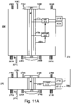
Fig. 11A shows transmit module 200 having electrical interface 201 between two
mechanical interfaces, and electrical interface 205 between two additional
mechanical
interfaces. Transmit module 200 enables an image picked up by a camera module
to be
transmitted to a remote location, either from the camera or from an
intermediate display
module.
CA 02718368 2010-09-10
WO 2009/112955 PCT/IB2009/005678
13
Electrical interfaces 201 and 205 are each a 5 pin interface, with the pins
arranged in
a quincunx pattern. Interface 201 is male and interface 205 is female. One of
the pins is
used for an analog video signal. A second pin is used for a power signal. A
third pin is used
as a power and/or video ground. The fourth and fifth pins are reserved for
future use, in
particular, for data. Each of the pins in interfaces 201, 205 is connected to
the corresponding
pin in the other of interfaces 201, 205, so that the signals can originate
from either interface.
The video signal input to transmit module 200 is supplied to encryption
circuit 202,
which uses any suitable encryption method to provide an encrypted video
signal. In some
embodiments, encryption circuit 202 is omitted. In other embodiments,
encryption circuit
202 is provided as a software program executing on a general purpose
processor.
The encrypted video signal is supplied from encryption circuit 202 to
transmission
circuit 203, which converts the baseband encrypted signal to a high frequency
signal for
wireless transmission. Typically, the high frequency signal is a channel at
900 MHz, 2.4
GHz, or 5.8 GHz but any suitable frequency may be used. Transmission circuit
203 is
manually controlled by channel selector 203A, that is, the user can select the
transmission
frequency. Channel selector 203A may be a knob, control screw, or any other
suitable
mechanism. Transmission circuit 203 provides the high frequency signal to
antenna port
211 B for wireless transmission. In some embodiments, antenna 204 is connected
directly to
antenna port 211B. Any suitable antenna may be used. In some embodiments,
antenna 204
is internal to transmit module 200. In the embodiment shown, antenna port 211E
is
connected to cable 272 and thence to signal booster 270, discussed below,
which is
connected to antenna 204.
Two mechanical interfaces surround each of electrical interfaces 201, 205, so
that
transmit module 200 may connect directly to a wider range of modules.
Additionally, as
described below, interface modules are provided to further extend the
connection options for
transmit module 200. In some embodiments, transmit module 200 has zero or one
mechanical interface per electrical interface; the number of mechanical
interfaces per
electrical interface may differ between electrical interfaces 201, 205.
Electrical interface 201 is between a first mechanical interface comprising
alignment
pins 209A and 209B, and a second mechanical interface comprising alignment pin
pairs
208A, 208B and spring-loaded latch 208C. The first mechanical interface is for
connection
CA 02718368 2010-09-10
WO 2009/112955 PCT/IB2009/005678
14
to, e.g., articulating module 120. The second mechanical interface is for
connection to, e.g.,
the bottom of extension pole 140.
Electrical interface 205 is between a first mechanical interface comprising
alignment
pin receptacles 206A and 206B, and a second mechanical interface comprising
alignment pin
receptacle pairs 207A, 207B and latch receptacle 207C. The first mechanical
interface is for
connection to, e.g., the top of extension pole 140. The second mechanical
interface is for
connection to, e.g., compact battery 220.
Signal booster 270 serves to boost its input signal from about 10 mwatts to 1
watt.
The input to signal booster 270 is the high frequency signal from transmitter
module 200.
The output of signal booster 270 is provided to antenna 204. Signal booster
270 is designed
to be plugged into transmitter module 200, and so has similar electrical and
mechanical
interfaces, not discussed here for brevity.
Figs. 12A-12B are three-dimensional front and back views of wireless
transmitter
module 200. Antenna port 211B is located on the opposite side of module 200
from channel
selector 203A.
Fig. 11B shows receiver module 210 having optional electrical interface 213,
and.
electrical interface 215 between a mechanical interface comprising alignment
pin receivers
216A, 216B, for connection to, e.g., the top of extension pole 140, or cord
170. Receiver
module 210 enables an image picked up by a camera module to be received at a
remote
location, either from the camera or from an intermediate display module.
Electrical interfaces 213 and 215 are each a 5 pin interface, with the pins
arranged in
a quincunx pattern, as discussed above.
A high frequency signal from transmit module 200 is received at antenna 214,
and
provided to receiver circuit 211 which converts the received signal from a
high frequency.
signal to a baseband signal, and provides the baseband signal to decryption
circuit 212.
Typically, the high frequency signal is a channel at 900 MHz, 2.4 GHz, or 5.8
GHz, but any
suitable frequency may be used. Receiver circuit 211 is manually controlled by
channel
selector 211A, that is, the user can select the reception frequency. Channel
selector 211A
may be a knob, control screw, or any other suitable mechanism.
Decryption circuit 212 uses any suitable decryption method to provide a
decrypted
video signal. In some embodiments, decryption circuit 212 is omitted. In other
CA 02718368 2010-09-10
WO 2009/112955 PCT/IB2009/005678
embodiments, decryption circuit 212 is provided as a software program
executing on a
general purpose processor.
Orientation pin receptacle 217 is provided on one side of receiver module 210,
to
facilitate coupling with display tray 280 (discussed below).
Figs. 13A-13B are three-dimensional front and back views of wireless receiver
module 210. Antenna port 214A is located on the side of module 210.
Fig. 11C shows compact battery 220 having male electrical interface 221
between
alignment pin pairs 228A, 228B and spring-loaded latch 228C, and having female
electrical
interface 222 and on/off switch 223. Compact battery 220 is designed to accept
AA
batteries, such as NiMH, Lilon, alkaline AA, rechargeable AA batteries or
other AA
batteries. Compact battery 220 is external to any module it connects to, for
enhanced
reliability, that is, an external battery avoids getting rain, sand or dust in
an internal battery
receptacle. Compact battery 220 is adapted to be placed directly into a
charger that is
connected to AC power, so that the batteries inside compact battery 220 can be
charged
while they are inside compact battery 220.
Figs. 14A-14B are three-dimensional front and back views of compact battery
220.
Figs. 14C-14D are three-dimensional front and back views of transmitter module
200
connected to compact battery 220.
Interface modules 230, 240, 250 are discussed below. Each of these modules has
two
electrical interfaces, each electrical interface having five pins arranged in
a quincunx pattern,
as described above.
Fig. 11D shows interface module 230 having male electrical interface 231
between
alignment pins 232A, 232B that use a secondary interlock mechanism discussed
below.
Interface module 230 is the first component to use this secondary interlock
mechanism.
Other components of the present modular imaging system will also be
manufactured with the
secondary interlock mechanism. Interface module 230 also has female electrical
interface
234 located between alignment pin receptacle pairs 237A, 237B and latch
receptacle 237C.
Figs. 15A-15B are three-dimensional front and back views of interface module
230.
Fig. 11E shows interface module 240 having female electrical interface 241,
and
female electrical interface 244 between alignment pin receptacle pairs 247A,
247B and latch
receptacle 247C.
CA 02718368 2010-09-10
WO 2009/112955 PCT/IB2009/005678
16
Fig. 11F shows interface module 250 having hooded electrical interface 250,
and
electrical interface 252.
Fig. 11G shows dual power module 260 having electrical interfaces 266, 269,
each
electrical interface having five pins arranged in a quincunx pattern, as
described above, and
also having battery interfaces 267, 268 adapted for connection to battery 185,
discussed
above.
Battery life depends on the age of the battery, the usage environment, and
what is
connected to the battery. For display module 180, battery 185 lasts around 5-
10 hours. For
wireless receiver module 210, battery 185 provides power for about 6-8 hours.
When using
transmitter module 200 in unattended operation, such as with extension pole
140, as a
temporary wireless transmitter tower, it is desirable to have a longer
unattended time than is
possible with one battery. Dual power module 260 enables two instances of
battery 185 to
be used in conjunction with a third battery, such as compact battery 220,
providing power for
up to 27 hours. This is particularly useful for unattended surveillance.
Instances of dual power module 260 can be connected in daisy-chain fashion, to
provide power to a device or devices for still longer amounts of time.
Fig. 11H shows display accessory tray 280 adapted to be coupled to the bottom
of
display 180, so that accessories can be conveniently attached to display 180,
such as wireless
receiver module 210. Display accessory tray 280 has orientation pin 281 that
fits into
orientation pin receptacle 217 of receiver module 210.
Figs. 16A-16D are three-dimensional top, front, bottom and side views of
display
accessory tray 280.
Fig. 16E is a three-dimensional front view of display accessory tray 280
connected to
display module 180 that is connected to battery 185.
Figs. 16F-16G are three-dimensional top and bottom views of display accessory
tray
280 connected to wireless receiver module 210.
Fig. 16H is a three-dimensional bottom view of display accessory tray 280
connected
to display module 180 and wireless receiver module 210; display 180 is also
connected to
battery 185.
Fig. 111 shows tripod 290 adapted to hold extension pole 140 in an upright
position
using a cam lock mechanism, thus enabling extension pole 140 to serve as an
antenna mast.
CA 02718368 2010-09-10
WO 2009/112955 PCT/IB2009/005678
17
Figs. 17A-17B are three-dimensional unfolded and folded views of tripod 290.
Legs
291A, 291B, 291C have ground spikes 295A, 295B, 295C, respectively, that fold
into
ground spike holders 296A, 296B, 296C. In some embodiments, the ground spikes
are
omitted. Tripod 290 has top collar 293 that slides up and down an extension
pole (not
shown) equipped with latch lever 298 for tightening top collar 293 when it is
at a suitable
position. Tripod 290 has bottom collar 294 with a lever lock (not shown) to
clamp the
bottom of an extension pole in place. Tripod 290 is designed to fold around
extension pole
140 while connected thereto, for ease in carrying. Tripod 290 raises the
bottom of extension
pole 140 from the ground or other surface, thereby protecting any coiled cable
plugged into
the bottom of extension pole 140 without need for a cord protector module.
Figs. 18A-I8H are block diagrams showing the components of Figs. 3A-3
I and 1IA-11I arranged in exemplary transmit configurations.
Fig. 18A shows camera module 110 connected to articulating module 120
connected
to first interface module 230 connected to wireless transmitter 200 connected
to compact
battery 220 connected to cord 170 connected to dual power module 260 that is
connected to
two instances of battery 185. An alternative form of this configuration omits
cord 170, dual
power module 260 and both instances of battery 185. This configuration is
useful in
confined space environments and in covert operations where a user may want to
hide or
camouflage the transmission / camera assembly.
Fig. 18B shows camera module 110 connected to articulating module 120
connected
to a first instance of cord 170 connected to second interface module 240
connected to
wireless transmitter 200 connected to compact battery 220 connected to a
second instance of
cord 170 connected to dual power module 260 that is connected to two instances
of battery
185. An alternative form of this configuration omits cord 170, dual power
module 260 and
both instances of battery 185. This configuration is useful as described above
with the
added benefit of optimizing transmitter position. In applications where users
want to mount
a camera on the manipulator arm of a robot, this configuration reduces the
payload size and
weight allowing use on lighter weight robots. The bearing weight further
reduced by using
interface module 250 instead of the articulation shown.
Fig. 18C shows camera module 110 connected to articulating module 120
connected
to first interface module 230 connected to wireless transmitter 200 connected
to extension
CA 02718368 2010-09-10
WO 2009/112955 PCT/IB2009/005678
18
pole 140 connected to compact battery 220 connected to cord 170 connected to
dual power
module 260 that is connected to two instances of battery 185. An alternative
form of this
configuration omits cord 170, dual power module 260 and both instances of
battery 185.
This configuration is useful for optimized transmission by using the extension
pole as a
transmission mast.
Fig. 18D shows camera module 110 connected to articulating module 120
connected
to extension pole 140 connected to wireless transmitter 200 connected to
compact battery
220 connected to cord 170 connected to dual power module 260 that is connected
to two
instances of battery 185. An alternative form of this configuration omits cord
170, dual
power module 260 and both instances of battery 185. In two-person team
environments, the
use of a coiled connecting cable between the search pole and display assembly
can be
problematic. This configuration allows greater freedom of movement and
wireless
connection to display assemblies worn by additional team members.
Fig. 18E shows camera module 110 connected to articulating module 120
connected
to extension pole 140 connected to a first instance of cord 170 connected to
second interface
module 240 connected to wireless transmitter 200 connected to compact battery
220
connected to a second instance of cord 170 connected to dual power module 260
that is
connected to two instances of battery 185. This configuration is useful in
environments
where camera is more usefully placed on a search pole with transmission
optimized by
placing transmitter independently.
Fig. 18F shows camera module 110 connected to articulating module 120
connected
to first interface module 230 connected to wireless transmitter 200 connected
to extension
pole 140 supported by tripod 290. Extension pole 140 is connected to compact
battery 220
connected to cord 170 connected to dual power module 260 that is connected to
two
instances of battery 185. This configuration is useful as described above,
with the added
benefit of free-standing operation.
Fig. 18G shows camera module 110 connected to articulating module 120
connected
to extension pole 140 supported by tripod 290. Extension pole 140 is connected
to wireless
transmitter 200 that is connected to compact battery 220 connected to cord 170
connected to
dual power module 260 that is connected to two instances of battery 185. This
configuration
CA 02718368 2010-09-10
WO 2009/112955 PCT/IB2009/005678
19
is useful as described above, but the transmitter is more optimally placed at
the base of the
pole/tripod assembly.
Fig. 18H shows camera module 110 connected to articulating module 120
connected
to extension pole 140 supported by tripod 290. Extension pole 140 is connected
to a first
instance of cord 170 connected to second interface module 240 connected to
wireless
transmitter 200 that is connected to compact battery 220 connected to a second
instance of
cord 170 connected to dual power module 260 that is connected to two instances
of battery
185. This configuration is useful as described above, but allows pole / camera
assembly to
be free-standing.
Figs. 181-18K are block diagrams showing the components of Figs. 3A-31 and 11A-
11I arranged in exemplary receive configurations.
Fig. 181 shows display 180 connected to battery 185, to display accessory tray
280
and to cord 170. Display accessory tray 280 supports wireless receiver module
210 that is
connected to display 180. This configuration is a chest mounted self-contained
receiver
assembly for body mounting.
Fig. 18J shows display 180 connected to battery 185 and to cord 170 that is
connected to wireless receiver module 210. This configuration is useful if
optimized
reception is required. This configuration allows the user to helmet mount the
receiver in
body mount configurations, and further allows placement of the receiver on the
outside of a
vehicle.
Fig. 18K shows display 180 connected to battery 185 and to cord 170 that is
connected to the bottom of extension pole 140 supported by tripod 290. The top
of
extension pole 140 is connected to wireless receiver module 210. This
configuration allows
use of an extension pole as a radio mast to optimize reception, and also
allows the user to
maintain cover in situations where enemy fire may pose a danger.
Figs. 19A-19H are diagrams referenced in explaining a spring-loaded locking
mechanism, used as a secondary interlocking mechanism.
Fig. 19A shows piece 300 about to connect to improved articulating module 320.
Piece 300 may be the top of extension pole 140 or the top of first interface
module 230.
Piece 300 has electrical interface 301 between alignment pins 305A, 305B,
having
respective radial channel 306A, 306B at their remote ends.
CA 02718368 2010-09-10
WO 2009/112955 PCT/IB2009/005678
Improved articulating module 320 has a face with electrical interface 321
between
alignment pin receptacles 325A, 325B. U-shaped collar 350 is shown in exploded
form; and
spring 340 that fits between U-shaped collar 350 and improved articulating
module 320 is
also shown in exploded form. Hole 345 surrounds an outer edge of U-shaped
collar 350
when U-shaped collar 350 is inserted in improved articulating module 320.
Fig. 19B shows a planar front view of U-shaped collar 350, that has "house-
shaped"
indentation 351 for receiving spring 340, and also has eccentrically shaped
holes 355A,
355B that are beveled. The bottom of holes 355A, 355B has a half-moon shaped
portion.
Fig. 19C shows a three-dimensional perspective view of U-shaped collar.
Fig. 19D shows the face of improved articulating module 320 when alignment
pins
305A, 305B are first inserted. The beveling around eccentrically shaped holes
355A, 355B
causes U-shaped collar 350 to move out of the way of alignment pins 305A, 305B
when they
are first inserted. The half-moon shaped portion at the bottom of holes 355A,
355B is
visible. Spring 340 is compressed.
Fig. 19E shows the face of improved articulating module 320 when alignment
pins
305A, 305B are seated. Spring 340 has expanded, exerting a force on U-shaped
collar 350
so that it moves away from alignment pins 305A, 305B, thus securing the radial
channels at
the remote ends of alignment pins 305A, 305B in the half-moon shaped portions
of
eccentrically shaped holes 355A, 355B.
Fig. 19F shows piece 300 inserted into improved articulating module 320.
Fig. 19G shows a detail view of piece 300 when it is first inserted into
articulating
module 320, corresponding to Fig. 19D. U-shaped collar 350 is seen to be
pushed in from
the perimeter of improved articulating module 320.
Fig. 19H shows a detail view of piece 300 when it is seated in articulating
module
320, corresponding to Fig. 19E. U-shaped collar 350 is seen to be pushed
outwards so that
its edge is flush with the edge of improved articulating module 320.
To remove piece 300 from improved articulating module 320, the user presses
inwards on an edge of U-shaped collar 350 visible in hole 345, allowing
alignment pins
305A, 305B to be easily slid out of alignment pin receptacles 325A, 325B.
The primary interlocking mechanism of electrical interface connectors used in
piece
300 and improved articulating module 320 is prone to breakage over time when
the electrical
CA 02718368 2010-09-10
WO 2009/112955 PCT/IB2009/005678
21
interface connectors are improperly used. That is, proper usage involves
pulling back an
outer collar on the male connector before pulling apart the electrical
interfaces. Improper
usage involves just pushing together or pulling apart the electrical
connectors without
pulling back the outer collar on the male connector. The secondary interlock
mechanism
provided by U-shaped collar 350 interacting with alignment pins 305A, 305B
ensures a solid
connection even when the primary interlock of electrical connectors 301, 321
does not
function properly due to wear from improper usage.
Advantageously, piece 300 is easy to insert and easy to deliberately remove,
but
difficult to accidentally remove.
Although illustrative embodiments of the present invention, and various
modifications thereof, have been described in detail herein with reference to
the
accompanying drawings, it is to be understood that the invention is not
limited to these
precise embodiments and the described modifications, and that various changes
and further
modifications may be effected therein by one skilled in the art without
departing from the
scope or spirit of the invention as defined in the appended claims.