Note : Les descriptions sont présentées dans la langue officielle dans laquelle elles ont été soumises.
CA 02719722 2010-09-27
1
Device and arrangement for preparing a liquid foodstuff
or semi-luxury product and portioned packaging
The invention relates to a device for preparing a
liquid foodstuff or semi-luxury product from a packaged
product contained in a portioned packaging according to
the preamble of claim 1. In addition, the invention
relates to an arrangement with a device of this type
and a portioned packaging. Such devices are used, above
all, for the preparation of beverages such as, for
example, coffee, tea or chocolate. The portioned
packagings can be capsules by means of which a dry
substance or at the most also other packaged goods can
be packaged in an advantageous manner.
Portioned packagings for the preparation of liquid
foodstuff or semi-luxury products have been known and
have been customary for a long time. EP 1 101 430 or EP
1 344 722, for example, have made known comparable
capsules. The capsules have a cup-like basic body
provided with a flange-like collar, said basic body
being closed in the region of the collar by means of a
film.
A device by way of which the extraction product
contained in such a capsule is extractable, is
described, for example, in WO 2007/017455. The device
includes a pivotable chamber part, which has a cavity
for accommodating the capsule. For simple handling of
the capsule by a consumer, the chamber part is aligned
vertically in an insertion position and horizontally in
a closed or extraction position.
Devices have become known then where the chamber parts
just carry out translatory movements. A device of this
type is shown, for instance, in EP 1 757 212 A2. In
this case, a generically comparable device is described
that has two chamber parts that are moveable in
relation to each other on a horizontal axis. The
CA 02719722 2010-09-27
2
capsule is inserted into an intermediate position by
the effect of gravitational force via laterally
arranged guiding and blocking means. To create an
extraction position, the blocking means are pushed to
the side when passing over the moveable chamber part,
the capsule thereby being released from the blocking
means. The mechanism for blocking and releasing the
capsule from the blocking means is com~.nratively
complex and requires special components.
Consequently, it is an object of the invention to
create a device of the aforementioned type that is
simplified with regard to functionality and design. It
is to be possible to produce the device easily. This
object is achieved according to the invention with a
device that has the features in claim 1.
Due to the fact that when the chamber parts -cove from
the open position into the closed position (closing
operation), the positioning unit acts on the collar of
the portioned packaging in such a manner that the
collar is releasable from the insertion position by
means of deforming, a considerable simplification of
the device is effected. Thus, with this type of
development of the device, there is no need for special
mobility of the positioning unit for releasing the
collar from the positioning unit as all that has to be
moved is the collar.
The portioned packaging can be a capsule that contains
an extraction product such as, for example, coffee or
tea. To achieve the insertion position, the portioned
packaging can be insertable into the positioning unit
preferably by means of gravitational force. One chamber
part can be realized as a capsule holder with a cavity
for accommodating the capsule and the other chamber
part can be realized as a closure part for closing the
cavity. At least one of the chamber parts, preferably
however each chamber part, can have associated
CA 02719722 2010-09-27
3
therewith means for penetrating the capsule and for
conducting the extractant through the closed extraction
chamber and through the capsule.
In a first embodiment, at least one of the chamber
parts is displaceable in the axial direction. For
release from the insertion position, the positioning
unit can have a stop face for the sectional folding
over or bending over of the collar in the axial
direction. Clearly, the positioning unit does not have
to be moveable in a transverse direction to the axial
direction. In other words, the positioning unit can be
non-moveable with reference to a transverse direction
preferably extending at right angles to the axial
direction.
It can be advantageous when the positioning unit
includes two holding jaws situated opposite each other
with guiding means in which the collar of the portioned
packaging is receivable in the insertion position. The
positioning unit is preferably realized in such a
manner that the capsule is aligned in the insertion
position approximately precisely with the extraction
position to be assumed subsequently. The capsule is
situated in the extraction position when the chamber
parts are situated in a preferably sealing closed
position and enclose the portioned packaging in the
chamber.
It can be particularly advantageous when the guiding
means form a guiding channel that tapers in the
insertion direction of the capsule. The respective
guiding channel can be wedge-shaped. Obviously,
however, it is also conceivable for the guiding channel
to have side walls that extend in parallel at least in
a sectional manner. The guiding channel. can be in the
form of a groove.
CA 02719722 2010-09-27
4
To secure the insertion position, the guiding channel
can be defined. In the event of a guiding groove, it
can be closed for example in the insertion direction by
a groove closure that is realized preferably in a
complementary manner to the collar. As an alt:eernative,
the guiding groove can have a groove bottom that tapers
in the insertion direction. The two groove bottoms
lying opposite each other can consequently de.`ine a V-
shape or wedge shape.
For a precise securement of the insertion po.-;ition it
can be advantageous when the collar is held in a
clamping manner in the guiding channel in the insertion
position. Obviously, however, it is also conceivable to
provide a clearance fit in the insertion position.
With regard to functionality and handling, i.'_ can be
advantageous when, with reference to the nsertion
direction, the guiding means have an insertion portion
and a positioning portion connected thereto, wherein
the positioning portion is set back in relation to the
insertion portion for the passing of one of the chamber
parts during the closing operation. The set-back
positioning portion has the further advantage that the
overlapping region between positioning unit and collar
of the portioned packaging is reduced, thereby
simplifying the deforming of the collar.
It can be particularly advantageous when the guiding
means is realized with groove-like guiding channels, a
guiding channel in a portion that secures the insertion
position having a maximum groove depth of 2 mm,
preferably a maximum depth of 1 mm. Theoretically it
would also be conceivable to provide the guiding
channel without a groove bottom or with a groove bottom
that has been deepened further. In this case, the
positioning unit would have to be realized in such a
manner that the maximum penetration depth of the collar
into the guiding channel is 2 mm, preferably 1 mm. The
CA 02719722 2010-09-27
positioning unit could also have a part circular-shaped
accommodating means for the collar extending over a
sector.
5 Entrainment means can be located on the positioning
unit, by way of which entrainment means the capsule is
removable from a cavity formed by one of the chamber
parts during an opening operation for restoring the
open position from the closed position.
The entrainment means can be an undercut located on the
holding jaw, via which undercut the collar is
engageable during the opening operation for pulling out
the cousule in the axial direction.
In addition it can be advantageous when the collar is
supportable on a holding edge, which is moveable in the
axial direction in relation to the positioning unit and
is associated with one chamber part. The holding edge,
in this case, can define a bending point for the
folding over of the collar during the closing
operation.
It can be particularly advantageous when a beveling or
recess connects to the holding edge for the short-term
reception of the folded-down collar during the closing
operation. Unwanted damage or jamming of the collar can
be avoided in this manner.
In one advantageous embodiment, one chamber part can be
located in the device in a fixed manner and the other
chamber part in a moveable manner. In this case, the
positioning unit can be moveable in the axial direction
together with the moveable chamber part.
The fixed chamber part can be dimensioned with regard
to its outer configuration in such a manner that it is
insertable between the holding jaws during the closing
operation.
CA 02719722 2010-09-27
6
A further aspect of the invention relates to an
arrangement for preparing a liquid foodstuff or semi-
luxury product with a portioned packaging and the
afore-described device.
Finally the invention also relates to a portioned
packaging, in particular a capsule for us( in the
afore-described device. The portioned packaging is
characterized by a preferably circumferenti_a~ collar,
which is realized so as to be flexible in sucl,, a manner
that during the closing operation, said collar is
deformable by the positioning unit during the closing
operation for releasing the holding impingement in the
insertion position. At least the collar, ~:referably
however also the capsule body connecting to the collar
can be produced from a flexible material that has
resilient restoring characteristics after def'rmation.
Thanks to said restoring characteristics, the collar is
only deformed for a short time during the closing
operation. Once the closing operation has been
concluded, i.e. therefore in the closed position, the
collar is situated back in its original position. The
collar, in this case, can extend outwards from the
capsule body in the radial direction.
Further advantages and individual features of the
invention are produced from the following do -cription
of exemplary embodiments and the drawings, in which:
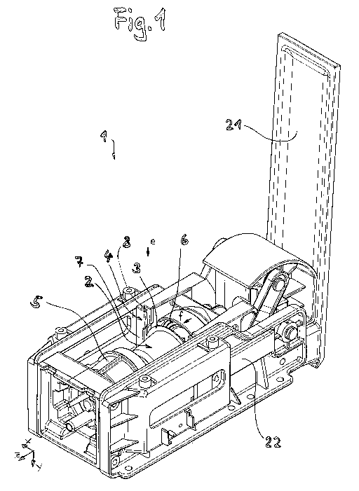
Figure 1 shows a perspective representation of a device
according to the invention in the open
position with a capsule in the insertion
position,
figure 2 shows a top view of the device in figure 1,
but without a capsule,
CA 02719722 2010-09-27
figure 3 shows a longitudinal section through the
device in the open position (sectional plane
w-w in figure 2), before the capsule is
inserted,
figure 4 shows a detailed view from figure 2 with an
enlarged representation of a positioning unit,
figure 5 shows the enlarged positioning unit from the
representation in figure 3,
figure 6a shows a cross section through the device
(sectional plane m-m) in figure 4,
figure 6b shows another cross section representing half
the device (sectional plane k-k) in figure 4,
figure 6c shows the cross section in figure 6b, but
with a capsule inserted,
figure 6d shows a greatly enlarged representation of
the detail F in figure 6c,
figure, 7 shows a top view of a device in the open
position with a capsule inserted,
figure 8 shows a longitudinal section through the
device in the open position with a capsule in
the insertion position,
figure 9 shows a top view of the device in figure 7,
but after a first part step of the closing
operation (without actuating-lever),
figure 10 shows a longitudinal section through the
device in the position in figure 9 (with
actuating-lever),
CA 02719722 2010-09-27
8
figure 11 shows a section through the device (sectional
plane q-q) in figure 10,
figure 12 shows a greatly enlarged representation of
the detail D in figure 11,
figure 13 shows the detail D in figure 12, h.u after a
further second part step of the closing
operation,
figure 14 shows the device in figure 11 after further
continuation of the closing movement in
relation to figure 13,
figure 15 shows a greatly enlarged representation of
the detail E in figure 14,
figure 16 shows a top view of the device in figure 14
after total closure (closed position),
figure 17 shows a longitudinal section through the
device in figure 14 or 16 in the closed
position,
figure 18 shows a top view of the devisee after
restoring the open position with the capsule
removed,
figure 19 shows a longitudinal section thr:)ugh the
device in figure 18 with a capsule dropping
out,
figure 20 shows a top view of a sectional
representation of the device in the position
in figure 18,
figure 21 shows the detail in figure 15, but with a
representation of the removal operation of the
capsule out of a cavity of a chamber part and
CA 02719722 2010-09-27
9
figure 22 shows a perspective representation of a
device according to a second exemplary
embodiment.
Figure 1 shows a device 1 according to the invention in
the form of a module that can be installed, for
example, in a coffee machine. The contents of a capsule
2 containing coffee powder can be extracted using a
device of this type. Obviously the capsule can also
contain other packaged products, in particular e.g.
soluble dry substances. The capsule 2 comprises a pot-
like or cup-like capsule body, which is preferably
produced from a plastics material such as, for example,
polypropylene and can be produced by using a deep-
1`ED
drawing method or an injection molding method. A
collar, given the reference 3, connects to the capsule
body, said collar defining an open end of the capsule
body. The capsule is closed by means of a cover film
that, as a rule, is also produced from plastics
material.
The device described below is basically suitable for
all types and shapes of portioned packagings that are
provided with collars.
The device 1 has two chamber parts 5 and 6, which are
displaceable in relation to each other in the axial
direction z. In the case of the present exemplary
embodiment, the chamber part 6 formed as a closure part
is moveable, whereas the other chamber part 5 is
located in a fixed manner in the device 1. The chamber
part 5 is developed as a capsule holder with a cavity
in which the capsule 2 is accommodatable. The capsule
2 is positioned with the assistance of a positioning
unit 4 in an insertion position between the chamber
parts 5 and 6 that are spaced apart in the open
position. The moveable chamber part 6 is mounted so as
to be displaceable between two support halves 22 of the
module. A Cartesian coordinates system is indicated by
x, y and z. An axial direction is indicated by z. The
CA 02719722 2010-09-27
closing and opening operation is effected in this
direction. The corresponding closing direction is
identified by an arrow f. The insertion direction is
indicated by an arrow e. The closing movement is
5 effected manually by actuating a pivot lever 21. The
device 1 can be installed advantageously, horizontally
aligned, in a corresponding machine. This type of
installation makes it possible for the capsule 3 to be
able to be moved into the insertion position in a
10 simple manner by means of gravitational force.
Obviously, other types of installation (e.g. aligned
vertically instead of horizontally) are also
conceivable.
Each of the chamber parts 5 and 6 has means (not shown)
for penetrating the capsule and for conducting the
extractant through the capsule. In the following
figures of the first exemplary embodiment, however, for
reasons of simplicity, there is no representation of
the penetration means (cf. however figure 22).
In figures 2 and 3 as well as 7 and 8, the device 1 is
shown in top view and a lateral longitudinal sectional
representation. As can be seen in figure 3, the capsule
2_5 2 can be inserted into the device 1 from above. The
positioning unit 4 has in each case laterally arranged
holding jaws 7 with guiding channels 8 into which the
collar 3 of the capsule 2 is insertable. In figure 8
the capsule 2 is finally recognizable in its insertion
position in the device 1.
It cart clearly be seen from figures 4 and 5 that the
guiding channel 8 is in the form of a guiding groove.
The references 18 and 18' are given to the side walls
of the guiding channel 8, between which the collar (not
shown here) is accommodatable in the manner of a
sandwich. The guiding channel 8 tapers in the insertion
direction e. The two side walls 18 and 18' located
CA 02719722 2010-09-27
11
opposite each other are evidently aligned in a wedge-
shaped manner.
Figures 5 and 6a show, among other things, that an
insertion portion 14 with a positioning portion 15
connected thereto is provided at the guiding channel.
The aim of the first portion 14 is to enable .s simple
an insertion of the capsule as possible. The second
portion 15 is set back in relation to the portion 14,
the oppositely situated chamber part 5 on the one hand
thereby being moveable past. On the other hand, an
advantageous deforming (described in more detail below)
of the collar is allowed for in this manner. Figure 6b
shows that the groove bottom 17 of the guiding channel
is realized as a wedge face that tapers inclinedl.y
downward. The reference 19 is given to an injector
bottom of the closure part 6, on which an injector
plate (not shown) with penetration means is attachable.
Figure 6c shows the capsule 2 in the insertion position
in the positioning unit. With reference to the
insertion direction, the groove bottom 17 initially
extends straight, but is developed in a circular manner
in this section complementarily to the capsule edge in
a portion that secures the insertion position. The
diameter of the edge 3 is identified by d and is, for
example, 40 mm. Details of the precise insertion
position can then be seen in figure 6d. As shown in
figure 6d, the maximum depth of penetration of the
collar 3 in the guiding channel is relatively small.
The depth of penetration, given the reference t, is ca.
0.7 mm with a collar diameter of 40 mm. The broken line
24 indicates the inwardly turned boundary of the side
wall (18) of the guiding channel. It can be seen in
figure 8 that the capsule 2 is aligned precisely
X35 coaxially to the cavity 11 thanks to the positioning
unit 8.
In figures 9 to 11 the chamber part 6 together with the
positioning unit 4 has been moved a first part in the
CA 02719722 2010-09-27
12
f-direction. As can be seen in figure 12, the collar 3
here abuts against a holding edge 9 of the fixed
chamber part 5. It can also be seen in figure 12 that
a beveling 10 connects to the holding edge 9. If the
holding jaw 7 is then moved further in the f-direction,
the collar 3 becomes bent over or folded over. The side
wall 18 of the guiding channel 8 forms for this purpose
a corresponding stop face that acts on the collar 3.
This position can be seen in figure 13. Figure 13
clearly shows as an example that the collar is folded
over. The folded-over collar 3' lies on the beveling
10, thereby avoiding being folded too far. If the
holding jaw 7 (together with the chamber part 6) is
then moved further in the closing direction, the
folded-over collar 3' moves off the sliding face, given
the reference 23, until, after reaching the undercut
16, it is released again from the sliding impingement.
By the capsule and in particular the collar 3 being
made from a resilient material, the collar assumes its
original shape (figure 15) on account of its restoring
force.
In figures 16 and 17 the device is shown in the closed
position. In this position the capsule 2 is enclosed in
the chamber that is formed by the chamber parts 5 and 6
pressed against each other. In this position an
extraction liquid such as, for example, water can be
conducted through the capsule. The pumps, valves, flow-
type heaters etc. necessary for this are known to the
skilled artisan and are not represented or described
here.
Once the beverage preparation has been completed, the
pivot lever 21 can be pivoted up and thus the opening
operation obtained. Figures 18 to 20 show an open
position after the pivoting up. As can be seen in
particular from figure 19, the capsule 2 drops out of
the device through its own weight at the latest in the
open position (or during the transition into the open
CA 02719722 2010-09-27
13
position) The capsule 2 is removable in a simple
manner under the effects of gravitational force through
the particular shape of the positioning unit 4.
The undercut 16 can be used to pull the capsule 2 out
of the cavity 11. If, namely, the holding jaw 7 is
moved in the g-direction during the opening operation,
the undercut 16 abuts against the collar 3 and thus
pulls the capsule out (figure 21).
As can be seen from the second exemplary embodiment in
figure 22, the positioning unit does not have to be
compulsorily rigid. The first exemplary embodiment in
figures 1 to 21 describes a positioning unit that is
certainly displaceable together with the moveable
chamber part; it is otherwise, however, non-moveable.
In particular, it is non-moveable with reference to the
x-direction (cf. figure 1). Figure 22 shows an
exemplary embodiment for the device according to the
invention where the positioning unit is at least
moveable in a limited manner. Said device is
characterized among other things in that double-walled
holding jaws 7 are provided for the positioning unit 4,
said ,:ruble-walled holding jaws being able to yield in
the manner of a parallelogram in the axial direction
during the closing operation. The holding jaws 4 are
components made of spring steel. In addition the
positioning unit in this case is located fixedly on the
frame and does not move together with the closure part
6. Rather this latter pushes the capsule out of the
positioning unit and transfers it into the capsule
holder 5 without it being able to drop out at the same
time. In addition, penetration means 12 for perforating
a cover film of the capsule 2 and for conducting the
extrac'.:ion medium can be seen in figure 22.