Note : Les descriptions sont présentées dans la langue officielle dans laquelle elles ont été soumises.
CA 02727786 2014-10-15
1
Street Pole and method for placing the street Dole
This invention relates to street poles and
to a method for placing such street poles.
Street poles are already well known in the art. They
extend along a longitudinal direction from a first end to a second end, the
first
end being provided to be fixed to the ground and the second end being
provided with for example lighting means, creating a street light. The second
end can however also be provided with for example traffic lights or general
traffic signals, such as road signs, traffic signs, etc. The street poles
generally
1 0
consist of a metal hollow cylindrical body which extends around the
longitudinal direction along a circumferential direction. The metal hollow
cylindrical body generally consists of at least one metal sheet which is bent
such as to form a circumferential side wall forming the hollow cylindrical
body,
which can have a round or polygonal cross-section. Adjacent edges of the
metal sheet(s) forming the hollow cylindrical body are then interconnected to
each other using fastening means.
The edges are hereto for example bent perpendicularly
with respect to the hollow cylindrical body towards the outside or the inside
of
the hollow cylindrical body such that adjacent overlapping flanges are
created.
2 0 The overlap however has a width which extends perpendicular to the
circumferential direction. The overlapping flanges can be interconnected by a
wide variety of fastening means such as by welding, bolting, soldering, etc.
When the flanges are provided on the outside of the hollow cylindrical body
the flanges protrude from the cylindrical hollow body, which is not attractive
from an aesthetic point of view and can cause injuries to people passing the
CA 02727786 2010-12-13
WO 2008/151862
PCT/EP2008/053853
2
pole. When the flanges are provided on the inside of the hollow cylindrical
body, the flanges are difficult to reach and are therefore difficult to
interconnect with the fastening means so that manufacturing of the street pole
is more difficult.
An example of a street pole having inwardly bent
flanges is shown in F194890B.
The street poles according to the state of the art
therefore have a configuration of the first and the second edges which does
not allow a satisfying interconnection of the first and second edges.
There is thus a need for a street pole in which the
interconnection of the first and second edges with fastening means can be
improved.
Thereto, the overlap has a width extending
substantially along the circumferential direction.
The inventor has found that a street pole having such
an overlap allows for interconnecting the first and the second edge by a wide
range of different fastening means such as welding, soldering, bolts, rivets,
screws, staples, gluing, etc. The street pole according to the invention
moreover is aesthetically attractive and is safer for people passing the
street
2 0 pole since it does not have a protruding flange.
Another option for fastening the adjacent metal
sheet(s) which is known from the state of the art is by bending metal sheet(s)
such that the adjacent edges become collinearly touching each other.
Interconnecting the collinearly touching adjacent edges is however difficult
and in order to achieve a sufficient interconnection of the first and the
second
edges is limited to welding and for example no bolts can directly be used in
this interconnection. In other words, the fastening means are limited to
welding. When the metal sheets are coated with zinc, for example by
galvanizing, before being bended and interconnected to form the street pole,
the adjacent edges can no longer, or least with increased difficulty, be
welded
together. So instead, the collinearly touching adjacent edges need to be
welded together before coating with for example zinc and can only be
galvanised after the first and the second edge have been welded together,
CA 02727786 2015-09-14
3a
which is more difficult and hence more costly. Since the street pole according
to the current
invention comprises an overlap of the first and the second edge, this problem
can be solved by
using other fastening means than welding, such as for example, bolts, nails,
rivets, screws or the
like since the fastening means of the street pole according to the current
invention are no longer
limited to welding.
Although US 4 644 715 A already describes a street pole in which the overlap
has a
width, extending along, the circumferential direction, the street poles
described by US 4 644 715
A, are not specifically designed to be impacted by, for example, a vehicle and
increase the risk of
mortality for the occupants of that vehicle when impacted, for example, during
an accident.
The street pole according to the invention is characterised in that the side
wall and the
fastening means are provided to split open along the overlap by breaking away
the fastening
means upon impact at a place of impact on the street pole, the hollow
cylindrical body, being
provided at the place of impact.
Such a street pole is designed to absorb an impact of for example a vehicle,
such that the
kinetic energy of an object, for example a vehicle, impacting the street pole
preferably is
substantially absorbed by the street pole by deformation of the street pole
due to the impact in
stead of for example deformation of the object, which is, in case of for
example a vehicle,
hazardous for the occupants of the vehicle. It has been found that accidents
involving such a
street pole impacted by a vehicle have a reduced mortality rate than accidents
involving a street
pole which does not absorb the energy of the impact with the vehicle. A street
pole having the
ability to absorb a significant amount of energy of an impact with a vehicle
is generally called a
street pole which is passively safe.
A street pole designed to absorb the energy of an impact with a vehicle is for
example
described by FI94890B.The street pole according to FI94890B however does not
comprise the
overlap of the street pole of the current invention, having a width which
extends substantially
along the circumferential direction, but instead has an inwardly bent fl ange,
as
briiiie-ciT26/64)-661
3b
described above. When a vehicle impacts the street pole according to
= FI94890B, the fastening means are provided to break away from the overlap
and the overlap as a further consequence splits open. However, it has been
found that the rigidity of the street pole according to F194890B generally
remains too large during impact with the vehicle such that an insufficient
amount of energy is absorbed by the street pole, which increases the amount
. _
=
=
=
r
=
CA 02727786 2010-12-13
t4/041?6,04
CA 02727786 2010-12-13
WO 2008/151862
PCT/EP2008/053853
4
of energy which needs to be absorbed by the car, causing an increased risk
of mortality and/or injuries to occupants of the vehicle.
The overlap of the street pole of the current preferred
embodiment however allows for an improved absorption of kinetic energy of
the vehicle. Without wanting to be bound by any theory the inventor believes
that this is caused by the direction of the width of the overlap, being
substantially along the circumferential direction. It has been found that the
impact of the vehicle onto the place of impact causes the hollow cylindrical
body to collapse in direction of the impact. As a consequence a first part and
1 0 a second part of the side wall of the hollow cylindrical body, the
second part
opposing the first part along the direction of the impact are pushed together
in
direction of the impact and a third and a fourth part of the side wall of the
hollow cylindrical body, the fourth part opposing the third part along a
direction
substantially perpendicular to the direction of the impact, are pushed away
from each other. The relative movement of the first, second, third and fourth
part causes the two edges to move in opposite directions along the width
direction of the overlap so that the street pole splits open in longitudinal
direction along the overlap by breaking away the fastening means.
The inventor has found that such an opposing
movement of the edges causes the rigidity of the street pole to drop
significantly upon impact, which increases the amount of energy which can be
absorbed by the street pole of the current invention. Without wanting to be
bound by any theory the inventor believes that the opposing movement of the
edges along the width direction of the overlap causes a shear effect which
2 5 causes an improved breaking away of the fastening means.
The inventor also found that the rigidity of the street
pole of the current invention which has not been impacted remains
substantially the same. The street pole according to the current invention in
other words allows the rigidity of the street pole to be significantly reduced
3 0 during impact whereas sustaining the rigidity of the street pole before
impact.
A more preferred embodiment of the street pole
according to the current invention is characterised in that the fastening
means
are rivets.
CA 02727786 2010-12-13
WO 2008/151862
PCT/EP2008/053853
The inventor has found that by interconnecting the two
edges with rivets, the interconnecting of the two edges becomes increasingly
easy and even edges of for examples galvanised steel can for example be
interconnected. Moreover, although the rivets provide the unimpacted street
5 pole with sufficient rigidity, the rivets are also more easily broken
away by the
opposing movement of the edges along the width of the overlap during impact
so that the amount of energy absorbed by the street pole is further increased,
improving the passive safety of the street pole.
The invention also relates to a method for placing a
street pole according to the invention, the street pole being characterised in
that the side wall and the fastening means are provided to split open along
the overlap by breaking away the fastening means upon impact at a place of
impact on the street pole, the hollow cylindrical body, being provided at the
place of impact, characterised in that the width of the overlap etends
substantially along a direction substantially parallel to a direction of
oncoming
traffic.
The inventor has found that when such a positioned
street pole is hit by a vehicle moving substantially along the direction of
oncoming traffic, the opposing movements of the first and second edge along
2 0 the width direction of the overlap is further increased, resulting in
an improved
absorption of the kinetic energy of the vehicle by the street pole.
Other details and advantages of the street pole
according to the invention and the method for placing the street pole
according to the invention will become apparent from the enclosed figures
2 5 and description of preferred embodiments of the invention.
Figure 1 shows a cross-section of a preferred
embodiment of the street pole according to the invention.
Figure 2 shows a cross-section of a different
embodiment of the street pole according to the invention.
30 Figure 3 shows a preferred embodiment of a street
pole according to the invention.
Figure 4 shows a different embodiment of a street pole
according to the invention.
CA 02727786 2010-12-13
WO 2008/151862
PCT/EP2008/053853
6
Figure 5 shows a street pole according to the invention
which has been impacted by a vehicle.
Figures 6a ¨ 6d successively show the effect of a
vehicle impacting a street pole according to the invention during the impact
of
the vehicle with the street pole.
A street pole 1 according to the invention is shown in
figure 3 and 4. The street pole 1 shown in figures 3 and 4 is fixed to the
ground. The street pole 1 can be fixed to the ground in any way known to the
person skilled in the art. The street pole 1 can for example be dug into the
ground, bolted to the ground, etc. When fixed to the ground the street pole 1
preferably extends in a substantial upright, preferably vertical, direction as
shown in figure 3. The street pole 1 can however also be provided to be
fastened to for example the wall of a building or the like, extending in a
substantial horizontal direction.
The street pole 1 shown in figures 3 and 4 extends
substantially along a longitudinal direction 8. The longitudinal direction 8
extends between a first and a second end.
The first end is provided to be fastened to a substrate.
In figures 3 and 4 the substrate shown, is substantially horizontal. The
substrate can however also extend substantially vertically or any other
direction. As discussed above, the substrate can for example be the ground, a
wall of a building, etc.
The first end can for example be provided to be dug
into the ground. The first end can moreover be provided to be put at least
2 5 partly in cement. However, other known ways for fastening the first end
to the
substrate can be used such as for example bolting the first end to the
substrate.
The first end preferably comprises means for allowing
electrical wires to enter the street pole 1, for example to provide
electricity to
lighting or any other electrically powered means. Thereto, the first end
comprises for example an opening leading towards the interior of the street
pole 1. This is however not critical for the invention and the electrical
wires
can for example also be provided along the exterior of the street pole 1.
CA 02727786 2010-12-13
WO 2008/151862
PCT/EP2008/053853
7
The second end is provided to be provided with means
such as for example lights, street signs, traffic signs, traffic lights,
directions,
billboards, etc. The second end for example can be provided with one, two,
three, four or even more horizontally bent arms, each arm comprising lighting
means, creating a lighting pole which can be used along streets or highways
to illuminate the streets or highways.
The street pole 1 can have any shape and dimension
which is deemed appropriate by the person skilled in the art. The longitudinal
direction 8 of the street pole 1 shown in figures 3 and 4 is substantially
straight. However, the street pole 1 can for example be bent along its
longitudinal direction 8, for example when it is provided to be mounted to an
upright substrate.
The street pole 1 comprises a hollow cylindrical body
6. The hollow cylindrical body 6 extends around the longitudinal direction 8
along a circumferential direction 9. A cross section of such a hollow
cylindrical
body 6 is for example shown in figures 1 and 2.
The hollow cylindrical body 6 can be provided
anywhere along the longitudinal direction 8 of the street pole 1. The street
pole 1 can for example comprise a first longitudinal part not being hollow but
being solid, for example, wood, plastic, etc., and a second longitudinal part
being formed by at least one hollow cylindrical body 6. The first and second
longitudinal part can be provided anywhere along the longitudinal direction 8
such that the first longitudinal part is provided near the first end and the
second longitudinal part is provided near the second end, but preferably the
first longitudinal part is provided near the second end and the second
longitudinal part is provided near the first end. It is preferred that the
street
pole 1 is made of at least one hollow cylindrical body 6. Figure 4 shows for
example a street pole 1 being made of different subsequent hollow cylindrical
bodies 6. Preferably, the street pole 1 however is made of a single hollow
cylindrical body 6, as shown in figure 3.
The inventor has found that when the street pole 1 is
made of a single hollow cylindrical body 6, the street pole 1 can be easily
made.
CA 02727786 2010-12-13
WO 2008/151862
PCT/EP2008/053853
8
The hollow cylindrical body 6 can be made of any
material such as plastic, wood, metal such as for example aluminium, steel,
stainless steel, galvanised steel, etc.
The cylindrical body 6 can have any shape and
dimensions deemed appropriate by the person skilled in the art.
The dimensions of the hollow cylindrical body 6
preferably are substantially determined by its length and its diameter 12. The
length of the cylindrical body is measured along the longitudinal direction 8
of
the street pole 1, whereas the diameter 12 is defined as the diameter of an
1 0 arc defining the circumferential direction 9 of the hollow cylindrical
body 6, as
shown in figures 1 and 2.
The length of the hollow cylindrical body 6, as
discussed above, preferably substantially equals the length of the street pole
1. The diameter 12 of the hollow cylindrical body 6 can be determined by the
person skilled in the art. However, the length of the hollow cylindrical body
6
can also be substantially longer or shorter than the length of the street pole
1.
The shape of the hollow cylindrical body 6 is
substantially determined by the shape of the cross section of the hollow
cylindrical body 6. Two examples of shapes of cross sections, polygonal and
2 0 round, are respectively shown in figures 1 and 2. Any other shape of
the cross
section is however possible and can be determined by the person skilled in
the art such as for example, a regular or irregular polygon having 3, 4, 5, 6,
7,
8, 9, 10, 11, 12, 13, 14, 15, 16, 17, 18, 19, 20 or even more vertices 13, an
arcuate shape such as an ellipsoid, etc.
The cross section of the hollow cylindrical body 6 can
change along the length direction of the hollow cylindrical body 6. The cross
section can for example become larger or smaller along the length direction or
can remain substantially constant.
Preferably, the cross section of the hollow cylindrical
body 6 becomes smaller in a direction from the first end of the street pole 1
towards the second end of the street pole 1, as shown in figures 3 and 4,
when the hollow cylindrical body 6 has a polygonal cross section.
Preferably, the cross section of the hollow cylindrical
CA 02727786 2010-12-13
WO 2008/151862
PCT/EP2008/053853
9
body 6 is substantially constant along the longitudinal direction 8 of the
street
pole 1 when a round cross section is used as shown in figure 2.
The hollow cylindrical body 6 comprises a
circumferential side wall 7 forming the hollow cylindrical body 6. The
circumferential side wall 7 comprises a first 3 and a second 4 edge which
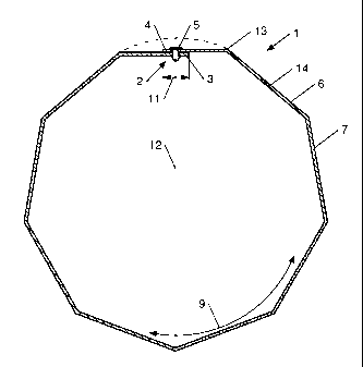
overlap to form an overlap 2. A top view of the overlap 2 is for example shown
in figure 1 and 2. The overlap 2 has a length 10 which extends substantially
along, preferably parallel to, the longitudinal direction 8, as shown in
figures 3
and 4. The length 10 of the overlap 2 can however extend along any possible
direction extending substantially along the longitudinal direction 8.
The circumferential side wall 7 can be a single piece or
can be made of different pieces. The circumferential side wall 7 preferably is
made of a single piece since the inventor has found that such a hollow
cylindrical body 6 can be more easily made. However, the hollow cylindrical
body 6 can also be made of a multitude of pieces which can be adjoined
using any method known in the art such as welding, soldering, gluing,
stapling, bolting, screwing, riveting, etc.
The overlap 2 can be positioned on every location
along the circumferential side wall 7. However, when the hollow cylindrical
body 6 has a polygonal cross section, the overlap 2 preferably is provided in
between two adjacent vertices 13 of the polygonal cross section. The overlap
2 more preferably is provided substantially equidistant from the two adjacent
vertices 13. The overlap 2 can however be provided at every location deemed
appropriate by the person skilled in the art such as for example at or near a
vertex 13.
The hollow cylindrical body 6 can comprise several
overlaps 2 but preferably comprises a single overlap 2 as shown in figures 1
and 2. The inventor has found that by providing the hollow cylindrical body 6
with a single overlap 2, the hollow cylindrical body can be more easily
manufactured.
The hollow cylindrical body 6 comprises fastening
means 5 for interconnecting the first 3 and second 4 edge of the
circumferential side wall 7. Any fastening means 5 known to the person skilled
CA 02727786 2010-12-13
WO 2008/151862
PCT/EP2008/053853
in the art can be used for example bolts, nuts, rivets, screws, nails,
staples,
glue, welds, solderings, etc.
When the overlap 2 of the first 3 and the second 4
edge causes one of the first 3 and the second 4 edge to be pressed to the
5 other edge 3, 4, for example due to a resilient force remaining after
bending
of the edges in the desired overlapping configuration, the friction caused by
the pressing of one edge to the other may cause that a sufficient
interconnection of the first 3 and the second 4 edge is reached. In that case
the fastening means 5 are the cooperating first 3 and second 4 edge and no
10 additional bolts, nuts, rivets, screws, nails, staples, glue, welds,
solderings,
etc. are necessary. In this case breaking away the fastening means 5 means
that the friction between the first 3 and the second 4 edge is overcome and
that first 3 and the second 4 edge are allowed to move in opposite directions
along the width direction of the overlap 2.
The fastening means 5 are preferably provided along
the entire length 10 of the overlap 2, more preferably on regular distances
when for example nuts, bolts, screws, nails, staples or the like are used or
preferably along the entire length 10 of the overlap 2 when for example
cooperating first 3 and second 4 edges, glue, welds, solderings, or the like
are
2 0 used. Other configurations of the fastening means 5 are however
possible.
The overlap 2 has a width 11 which extends
substantially along the circumferential direction 9. The first 3 and the
second 4
edge of the circumferential side wall 7 in other words overlap each other
along
the circumferential direction 9. The width 11 is for example shown in figures
1
and 2.
The width 11 of the overlap 2 can be determined by
the person skilled in the art. Preferably, the width 11 of the overlap is
determined in function of the fastening means 5. For example, when rivets,
bolts, nails, screws, staples, etc. are used to interconnect the first 3 and
the
second 4 edge of the hollow cylindrical body 6, the width 11 needs to be
sufficient to receive the fastening means 5 and to offer a sufficient
interconnection of the first 3 and the second 4 edge. When using other
fastening means 5 such as for example glue, welds, solderings, etc. the width
CA 02727786 2010-12-13
WO 2008/151862
PCT/EP2008/053853
11
11 needs to be adapted to the interconnecting characteristics of the fastening
means 5 such that the width 11 needs to be increased or can be decreased in
order to offer a sufficient interconnection of the first 3 and the second 4
edge.
The width 11 can for example be as small as 1mm for
some types of fastening means 5 or the width 11 can extend up to more than
100% of the circumference of the hollow cylindrical body 6 in which case the
side wall 7 comprises at least two layers wound around the longitudinal
direction of the street pole 1.
The inventor has found that an increased width 11 of
1 0 the overlap 2, increases the friction between the first 3 and the
second 4 edge
of the overlap 2 so that additional fastening means 5 such as bolts, nuts,
rivets, screws, nails, staples, glue, welds, solderings, etc. can be avoided.
Preferably, the width 11 of the overlap 2 is
substantially constant along the longitudinal direction 8 of the street pole
1.
This is however not critical for the invention and the width 11 can change
along the longitudinal direction 8 of the street pole 1.
The hollow cylindrical body 6 preferably is made of a
bendable material such as for example metal. This way the hollow cylindrical
body 6 can be made by bending a sheet 14 of the bendable material,
preferably a metal sheet, into the desired shape having the desired cross
section. However, any other material is possible as described above and the
hollow cylindrical body 6 can for example also be cast.
In case the hollow cylindrical body 6 has a polygonal
cross section, more preferably a regular polygonal cross section, as shown in
figure 1, the hollow cylindrical body 6 preferably is made by bending at least
one sheet 14 of the bendable material along longitudinal folding lines forming
the vertices 13 of the polygonal cross section. Preferably, these folding
lines
are created by pushing a longitudinal edge into and/or along the sheet of
bendable material. Any other way of making the hollow cylindrical body is
however possible.
More preferably, the hollow cylindrical body 6 in this
case has an uneven number of vertices and the overlap 2 is provided in
between two adjacent vertices 13, the last folding line being created being
the
CA 02727786 2010-12-13
WO 2008/151862
PCT/EP2008/053853
12
folding line opposing the overlap 2. The inventor has found that such bending
of the sheet 14 of bendable material allows the longitudinal edge to be
retracted more easily, after being pushed into and/or along the sheet 14 of
bendable material in order to create the folding line, in between the first 3
and
the second 4 edge before the overlap 2 is created.
In case the hollow cylindrical body 6 has a round cross
section, the hollow cylindrical body 6 preferably is made by rolling at least
one
sheet 14 of bendable material, preferably metal.
Although the hollow cylindrical body 6 preferably is
made of a single bent sheet 14, as shown in figures 1 and 2, the hollow
cylindrical body 6 can also be made of several bent sheets 14 forming the
different pieces of the circumferential side wall 7, as discussed above.
Preferably, the side wall 7 and the fastening means 5
are provided to split open along the overlap 2 by breaking away the fastening
means 5 upon impact at a place of impact 15 on the street pole 1, the hollow
cylindrical body 6, being provided at the place of impact 15.
Preferably, the side wall 7 and the fastening means 5
are provided to split open along the overlap 2 by breaking away the fastening
means 5 upon impact with a vehicle 16. The vehicle 16 can be any vehicle 16,
preferably motorised, known to the person skilled in the art such as a car,
truck, motorcycle, etc.
This is especially beneficial for street poles 1 which are
provided to be fixed to the ground since such poles 1 are generally provided
next to roads on which traffic passes to street pole 1.
With impact in the context of this application is meant
an impact caused when such a vehicle 16 drives into the street pole 1 for
example more than 0 km/h, more than 5 km/h, more than 10 km/h, more than
20 km/h or more than 30 km/h or even higher. However, the side wall 7 and
the fastening means 5 must be such as to resist normal forces acting on the
street pole 1 such as for example varying winds, relative small impacts
caused by for example parking vehicles, etc. when the street pole 1 has not
been impacted by vehicle 16.
Examples of a vehicle impacting such a street pole 1
CA 02727786 2010-12-13
WO 2008/151862
PCT/EP2008/053853
13
are shown in figures 5 and 6a ¨ 6d.
When the street pole 1 is impacted, the first 3 and the
second 4 edge of the side wall 7 move away from each other as described
and the fastening means 5 are broken away from the edges 3, 4. When the
impact is large enough, the first and second edge 3, 4 move even further
away until subsequent fastening means 5 are broken away. This process is
repeated until the impact has been fully absorbed, as shown in figure 5. Due
to the impact the first and the second edge 3, 4 can keeping moving away
from each other until the circumferential sidewall 7 is fully unfolded and
becomes substantially flat, as shown in figure 5.
Preferably, the street pole 1 is provided not to break
away from its substrate upon impact but to remain fixed to its substrate,
allowing the energy of the impact to be absorbed until the speed of the
vehicle 16 impacting the street pole 1 has been significantly reduced.
Therefore, after impact of the vehicle 16 with the street pole 1, the risk
that
the vehicle 16 impacts a further obstacle after impacting the street pole 1 is
significantly reduced. In order to achieve such a connection of the street
pole
1 to the substrate, the first end preferably is cast into cement, as discussed
above. However, this is not critical for the invention and any other
connection
of the street pole 1 to the substrate may be used.
A vehicle 16 impacting the street pole 1 causes the
street pole 1 to be impacted at the place of impact 15. The hollow cylindrical
body 6 then splits open at the place of impact 15. Subsequently, when the
impact is large enough the place of impact 15 moves along the longitudinal
direction 8 of the street pole 1 as shown in figures 6a ¨ 6d such that a part
of
the street pole 1 moves under the vehicle 16 while another part folds in the
direction of the vehicle 16, as shown in figure 5 and 6d. By keeping the
street
pole 1 fixed to the ground, the kinetic energy of the vehicle 16 can be
absorbed until the speed of the vehicle 16 is reduced. While the place of
impact 15 moves along the longitudinal direction 8 of the street pole 1, the
first and second edges 3, 4 at the moving place of impact 15 keep moving
away from each other along the width direction 11 of the overlap 2 such that
the fastening means are broken away and the overlap 2 splits open along the
CA 02727786 2010-12-13
WO 2008/151862
PCT/EP2008/053853
14
longitudinal direction 8 until the speed of the vehicle 16 has been
significantly
reduced. Preferably, the speed of the vehicle 16 after impact with the street
pole 1 is reduced such that it is less than 50 km/h measured after 12m after
the initial impact.
The part that folds in direction of the vehicle 16 can
fold onto the vehicle 16 or, preferably, next to the vehicle 16. When the
street
pole 1 is provided to fold next to the vehicle the occupants of the vehicle
are
even more protected.
The hollow cylindrical body 6 must be provided at the
place of impact 15 in order to be able to absorb the energy of the impact.
Therefore, the hollow cylindrical body 6 provided to split open upon impact is
preferably provided at a height which can be impacted by vehicles 16. The
hollow cylindrical body 6 is for example provided near the substrate. However,
the hollow cylindrical body 6 preferably extends along substantially the
entire
length of the street pole 1 along the longitudinal direction 8, as shown in
figures 3 and 4. When the overlap 2 extends along substantially the entire
length of the street pole 1, larger impacts can be absorbed since the
absorption of the impact by the splitting open of the hollow cylindrical body
6,
the braking away of the fastening means 5 and the unfolding of the hollow
cylindrical body 6 can continue along the entire length of the street pole 1.
A
same effect can also be achieved when the street pole 1 is formed of
subsequent hollow cylindrical bodies 6, as shown in figure 4.
The hollow cylindrical body 6 in such an embodiment
preferably is made from metal, such as for example steel, aluminium, etc.
More preferably the hollow cylindrical body 6 is made from steel.
Preferably, material of the side wall 7 of the hollow
cylindrical body 6 has a yield strength Re of between 50N/mm2 ¨ 700N/mm2,
preferably 200N/mm2¨ 550N/mm2, more preferably 330N/mm2¨ 410N/mm2.
Preferably, the material of the side wall 7 has a tensile
strength Rm of between 50N/mm2 ¨ 1350N/mm2, preferably 350N/mm2 ¨
1050N/mm2, more preferably 600N/mm2¨ 700N/mm2.
Preferably, the material of the side wall 7 has a
minimal elongation before breaking A80 of at least 5%, preferably, 15%, more
CA 02727786 2010-12-13
WO 2008/151862
PCT/EP2008/053853
preferably 21%.
Preferably, the side wall 7 has a thickness of between
20mm ¨ 0.5mm, preferably 10mm ¨ 1mm, more preferably 5mm - 1mm, even
more preferably 2mm.
5 Preferably, the hollow cylindrical body 6 has a
diameter 12 at the place of impact 15 of between 50mm ¨ 400mm, preferably
100mm ¨ 300mm, more preferably 150mm ¨ 250mm.
Preferably, the width 11 of the overlap 2 is at least
0.1%, preferably maximal 100%, more preferably between 0.1% and 10%,
10 most preferably between 2% and 3.5% of the circumference of the hollow
cylindrical body 6.
A first example is a street pole 1 consisting of a single
hollow cylindrical body 6 having a length of about 12m, a diameter of 240mm
near the first end of the street pole 1 and a substantially constant width 11
of
15 the overlap 2 of 20mm which is 2,6% of the diameter 12 near the first
end.
Another example is a street pole 1 consisting of a
single hollow cylindrical body 6 having a length of about 10m, a diameter of
208mm near the first end of the street pole 1 and a substantially constant
width 11 of the overlap 2 of 20mm which is 3,06% of the diameter 12 near the
first end.
Preferably, the fastening means 5 have a shear
strength, this is the strength in width 11 direction of the overlap 2, of
between
2000N ¨ 7000N, preferably 3000N ¨ 6000N, more preferably 4000N ¨ 5000N,
most preferably 4100N ¨ 4500N.
Preferably, the fastening means 5 are rivets since the
inventor found that they offer a good and easy interconnection of the first
and
the second edge 3, 4 while being provided to brake away when the first and
the second edge 3, 4 move away from each other and allowing an easy
interconnection of the first and the second edge 3, 4. However, any other
fastening means 5 can be used instead, as described above.
The invention also relates to a method for placing such
a street pole 1 in which the width 11 of the overlap 2 extends substantially
along a direction substantially parallel to the direction of oncoming traffic.
CA 02727786 2010-12-13
WO 2008/151862
PCT/EP2008/053853
16
More specifically the width 11 of the overlap 2 extends
substantially along a direction having an angle of between 0 ¨ 900, 0 - 180
,
0 - 45 , preferably 10 ¨ 300, more preferably 15 ¨ 25 , most preferably 20
with the direction of oncoming traffic.
The overlap 2 can however also be provided in any
other possible direction. The street pole 1 can for example be placed such
that the width 11 of the overlap 2 extends substantially along a direction
which
is substantially perpendicular to the direction of oncoming traffic or any
other
possible direction.