Sélection de la langue

Search

Sommaire du brevet 2730602 

Énoncé de désistement de responsabilité concernant l'information provenant de tiers

Une partie des informations de ce site Web a été fournie par des sources externes. Le gouvernement du Canada n'assume aucune responsabilité concernant la précision, l'actualité ou la fiabilité des informations fournies par les sources externes. Les utilisateurs qui désirent employer cette information devraient consulter directement la source des informations. Le contenu fourni par les sources externes n'est pas assujetti aux exigences sur les langues officielles, la protection des renseignements personnels et l'accessibilité.

Disponibilité de l'Abrégé et des Revendications

L'apparition de différences dans le texte et l'image des Revendications et de l'Abrégé dépend du moment auquel le document est publié. Les textes des Revendications et de l'Abrégé sont affichés :

  • lorsque la demande peut être examinée par le public;
  • lorsque le brevet est émis (délivrance).
(12) Demande de brevet: (11) CA 2730602
(54) Titre français: DISPOSITIF DE FIXATION PERFECTIONNE
(54) Titre anglais: IMPROVED SHACKLE
Statut: Réputée abandonnée et au-delà du délai pour le rétablissement - en attente de la réponse à l’avis de communication rejetée
Données bibliographiques
Abrégés

Abrégé anglais


There is disclosed a shackle for securing objects. The shackle includes a
substantially U shaped
member having opposite first and second ends, said first and second ends
having threaded first
and second apertures. The U shaped member is configured such that the first
and second
threaded apertures are co-axially aligned. The first and second threaded
apertures have
substantially identical diameters and substantially identical thread patterns.
The shackle further
includes a cylindrical pin having opposite first and second ends, a cross
sectional diameter and a
length, the first end of the pin having a first threaded portion, the cross
sectional diameter of the
pin and the threaded portion being configured such that the pin can be
threaded into both the first
and second threaded apertures of the U shaped member. Finally, a handle is
formed on the
second end of the pin and the length of the pin is selected such that the pin
can span both the first
and second threaded apertures.

Revendications

Note : Les revendications sont présentées dans la langue officielle dans laquelle elles ont été soumises.


CLAIMS:
1. A shackle comprising:
a substantially U shaped member having opposite first and second ends, said
first and
second ends having threaded first and second apertures, the U shaped member
being
configured such that the first and second threaded apertures are co-axially
aligned;
the first and second threaded apertures having substantially identical
diameters and
substantially identical thread patterns;
a cylindrical pin having opposite first and second ends, a cross sectional
diameter and a
length, the first end of the pin having a first threaded portion, the cross
sectional diameter
of the pin and the threaded portion being configured such that the pin can be
threaded into
both the first and second threaded apertures of the U shaped member;
a handle formed on the second end of the pin, the length of the pin being
selected such
that the pin can span both the first and second threaded apertures.
2. The shackle as defined in claim 1 wherein the pin has a second threaded
portion
positioned between the first and second ends of the pin and adjacent the
handle portion,
the second threaded portion configured to thread with both the first and
second threaded
aperture, the pin having a non-threaded portion separating the first and
second threaded
portions.
3. The shackle as defined in claim 2 wherein the first and second threaded
port
ions of the
pin are dimensioned such that the first and second threaded portions are mated
to the first
6

and second threaded apertures when the pin is fully threaded into the shackle
and the pin
spans the first and second ends of the U shaped member.
4. The shackle as defined in claim 3 wherein the non-threaded portion has a
length sufficient
to span between the first and second threaded apertures of the U shaped
member.
7

Description

Note : Les descriptions sont présentées dans la langue officielle dans laquelle elles ont été soumises.

CA 02730602 2011-02-04
TITLE: Improved Shackle
FIELD OF THE INVENTION
The invention relates generally to shackles.
BACKGROUND OF THE INVENTION
Shackles and U bolts are often used in various industry, including the
entertainment industry.
These shackles are generally used to secure heavy objects to a harness or
support. Most U bolt
type shackles consist of a U shaped member having opposite ends, with
apertures formed on each
of the opposite ends of the U shaped member. The apertures are coaxially
aligned and a long pin
is provided which is configured to pass into apertures to close off the U bolt
shackle. One of the
apertures is often provided with threading and the pin is generally provided
with corresponding
threading to permit the pin to be threaded into the shackle. It will be
appreciated that it is
necessary to disengage the pin with the U shaped member in order to attach the
shackle. This
requires the pin to be placed in a pocket for storage until the shackle is to
be closed. It will be
appreciated that in situations where an individual is using a plurality of
such shackles, there is
always the possibility that a pin may accidently be dropped when the user
attempts to thread the
pin into the shackle to close the shackle or when the shackle is being opened.
If the user is
attempting to secure a suspended object, dropping the pin may injure someone
standing below.
An improved shackle which makes it less likely for the pin to be accidentally
dropped is
therefore required.
1

CA 02730602 2011-02-04
SUMMARY OF THE INVENTION
In accordance with one aspect of the present invention, there is provided a
shackle for
securing objects. The shackle includes a substantially U shaped member having
opposite first
and second ends, said first and second ends having threaded first and second
apertures. The U
shaped member is configured such that the first and second threaded apertures
are co-axially
aligned. The first and second threaded apertures have substantially identical
diameters and
substantially identical thread patterns. The shackle further includes a
cylindrical pin having
opposite first and second ends, a cross sectional diameter and a length, the
first end of the pin
having a first threaded portion, the cross sectional diameter of the pin and
the threaded portion
being configured such that the pin can be threaded into both the first and
second threaded
apertures of the U shaped member. Finally, a handle is formed on the second
end of the pin and
the length of the pin is selected such that the pin can span both the first
and second threaded
apertures.
With the foregoing in view, and other advantages as will become apparent to
those skilled
in the art to which this invention relates as this specification proceeds, the
invention is herein
described by reference to the accompanying drawings forming a part hereof,
which includes a
description of the preferred typical embodiment of the principles of the
present invention.
DESCRIPTION OF THE DRAWINGS
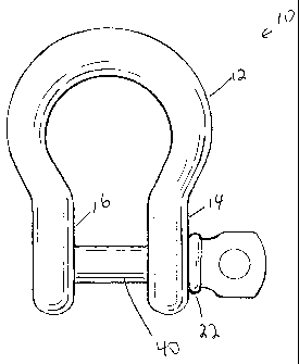
Figure 1 is a side view of a shackle made in accordance with the invention.
Figure 2 is a sectional view of the shackle shown in figure one.
Figure 3 is a front view of a shackle made in accordance with the invention
without the pin
2

CA 02730602 2011-02-04
portion.
Figure 4 is a back view of the shackle shown in figure 3.
Figure 5 is a side view of the pin portion of a shackle made in accordance
with the present
invention.
Figure 6 is perspective view of a shackle made in accordance with the present
invention showing
the pin in its fully inserted position.
Figure 7 is a perspective view of the shackle shown in figure 6 showing the
pin partially
removed.
In the drawings like characters of reference indicate corresponding parts in
the different
figures.
DETAILED DESCRIPTION OF THE INVENTION
Referring firstly to figure 7, a shackle made in accordance with the present
invention,
shown generally as item 10, includes a generally U shaped member 12 which is
typically made of
steel. U shaped member 12 is generally in the form of a U (or a horse shoe)
and consists of an
elongated bar of steel having a roughly cylindrical cross section and opposite
ends 14 and 16.
Ends 14 and 16 are somewhat flattened to accommodate threaded apertures 18 and
20. Apertures
18 and 20 are aligned with axis 28. Pin 22 is an elongated steel cylinder 24
having a length
sufficient to span apertures 18 and 20. Pin 22 is provided with a handle
portion 26 at one end to
make it easier to grasp and rotate the pin. Pin 22 has threaded portions 30
and 32 which are
configured to mesh with threaded apertures 20 and 18, respectively. Non-
threaded portion 40
separates threaded portions 30 and 32. Preferably, the lengths of the threaded
and non-threaded

CA 02730602 2011-02-04
portions of pin 22 are configures such that the non-threaded portion extends
between ends 14 and
16 when the pin is fully inserted into the U shaped member 12 as seen in
figures 6 and 2.
As best seen in figure 5, pin 22 has threaded portion 30 located at end 38 of
shaft 24.
Threaded portion 32 is positioned adjacent handle portion 26 and non-threaded
portion 40
extends between both threaded portions. The non-threaded portion between the
two threaded
portions permits less ware to a chain or rope (not shown) which may bear
against shaft 24.
As better shown in figures 1 and 2, pin 22 spans the gap separating ends 16
and 14 and
provides a means for closing shackle 10. Threaded portions 20 and 32 are
precisely threaded to
carefully thread with apertures 18 and 20, respectively, to permit a strong
connection between the
pin and the U shaped member.
As better seen in figure 6, shackle 10 may be provided with a lanyard 36 which
joins pin
22 to U shaped member 12. The lanyard permits pin 22 to be completely removed
from the U
shaped member without causing the pin to be moved too far away from the U
shaped member.
This decreases the likelihood of loosing or dropping the pin. However, it will
be appreciated that
in order to permit shackle 10 to function properly, lanyard 36 must be
sufficiently long to permit
pin 22 to be completely removed from U shaped member 12.
Returning back to figure 7, the advantage of the present shackle can be seen.
Since pin
22 is threaded at two portions on shaft 24 and since apertures 18 and 20 are
both threaded, it is
possible to put pin 22 in a position where both threaded portions 30 and 32
are disengaged, but
the pin is still mounted to U shaped member 12. Since aperture 18 is threaded,
threaded portion
30 prevents pin 22 from accidentally slipping out of aperture 18 and drop to
the floor. The
shackle, placed in the position illustrated in figure 7, is partially opened,
and can be used to pass
4

CA 02730602 2011-02-04
a rope or chain between ends 14 and 16, even though pin 22 is still partially
retained in the
shackle. This makes it possible to mount the shackle as required without
having to completely
remove the pin. To completely remove the pin, pin 22 is further rotated such
that threaded
portion 30 passes all the way past threaded opening 18.
A specific embodiment of the present invention has been disclosed; however,
several
variations of the disclosed embodiment could be envisioned as within the scope
of this invention.
It is to be understood that the present invention is not limited to the
embodiments described
above, but encompasses any and all embodiments within the scope of the
following claims.

Dessin représentatif
Une figure unique qui représente un dessin illustrant l'invention.
États administratifs

2024-08-01 : Dans le cadre de la transition vers les Brevets de nouvelle génération (BNG), la base de données sur les brevets canadiens (BDBC) contient désormais un Historique d'événement plus détaillé, qui reproduit le Journal des événements de notre nouvelle solution interne.

Veuillez noter que les événements débutant par « Inactive : » se réfèrent à des événements qui ne sont plus utilisés dans notre nouvelle solution interne.

Pour une meilleure compréhension de l'état de la demande ou brevet qui figure sur cette page, la rubrique Mise en garde , et les descriptions de Brevet , Historique d'événement , Taxes périodiques et Historique des paiements devraient être consultées.

Historique d'événement

Description Date
Demande non rétablie avant l'échéance 2016-02-04
Le délai pour l'annulation est expiré 2016-02-04
Réputée abandonnée - omission de répondre à un avis sur les taxes pour le maintien en état 2015-02-04
Requête visant le maintien en état reçue 2014-02-03
Requête visant le maintien en état reçue 2013-01-15
Demande publiée (accessible au public) 2012-08-04
Inactive : Page couverture publiée 2012-08-03
Inactive : CIB en 1re position 2011-04-07
Inactive : CIB attribuée 2011-04-07
Inactive : Certificat de dépôt - Sans RE (Anglais) 2011-02-22
Demande reçue - nationale ordinaire 2011-02-22
Déclaration du statut de petite entité jugée conforme 2011-02-04

Historique d'abandonnement

Date d'abandonnement Raison Date de rétablissement
2015-02-04

Taxes périodiques

Le dernier paiement a été reçu le 2014-02-03

Avis : Si le paiement en totalité n'a pas été reçu au plus tard à la date indiquée, une taxe supplémentaire peut être imposée, soit une des taxes suivantes :

  • taxe de rétablissement ;
  • taxe pour paiement en souffrance ; ou
  • taxe additionnelle pour le renversement d'une péremption réputée.

Les taxes sur les brevets sont ajustées au 1er janvier de chaque année. Les montants ci-dessus sont les montants actuels s'ils sont reçus au plus tard le 31 décembre de l'année en cours.
Veuillez vous référer à la page web des taxes sur les brevets de l'OPIC pour voir tous les montants actuels des taxes.

Historique des taxes

Type de taxes Anniversaire Échéance Date payée
Taxe pour le dépôt - petite 2011-02-04
TM (demande, 2e anniv.) - petite 02 2013-02-04 2013-01-15
TM (demande, 3e anniv.) - petite 03 2014-02-04 2014-02-03
Titulaires au dossier

Les titulaires actuels et antérieures au dossier sont affichés en ordre alphabétique.

Titulaires actuels au dossier
DAVID REPPEN
Titulaires antérieures au dossier
S.O.
Les propriétaires antérieurs qui ne figurent pas dans la liste des « Propriétaires au dossier » apparaîtront dans d'autres documents au dossier.
Documents

Pour visionner les fichiers sélectionnés, entrer le code reCAPTCHA :


Pour visualiser une image, cliquer sur un lien dans la colonne description du document. Pour télécharger l'image (les images), cliquer l'une ou plusieurs cases à cocher dans la première colonne et ensuite cliquer sur le bouton "Télécharger sélection en format PDF (archive Zip)" ou le bouton "Télécharger sélection (en un fichier PDF fusionné)".

Liste des documents de brevet publiés et non publiés sur la BDBC .

Si vous avez des difficultés à accéder au contenu, veuillez communiquer avec le Centre de services à la clientèle au 1-866-997-1936, ou envoyer un courriel au Centre de service à la clientèle de l'OPIC.


Description du
Document 
Date
(aaaa-mm-jj) 
Nombre de pages   Taille de l'image (Ko) 
Abrégé 2011-02-03 1 24
Description 2011-02-03 5 169
Revendications 2011-02-03 2 42
Dessins 2011-02-03 4 89
Dessin représentatif 2012-07-25 1 7
Certificat de dépôt (anglais) 2011-02-21 1 157
Rappel de taxe de maintien due 2012-10-08 1 111
Courtoisie - Lettre d'abandon (taxe de maintien en état) 2015-03-31 1 172
Rappel - requête d'examen 2015-10-05 1 116
Taxes 2013-01-14 2 59
Taxes 2014-02-02 1 30
Taxes 2014-02-02 2 65