Note : Les descriptions sont présentées dans la langue officielle dans laquelle elles ont été soumises.
CA 02748146 2011-08-08
110226-WO-00: 910722
DESCRIPTION
TITLE OF THE INVENTION
Redox Flow Battery
TECIINICAL FIELD
The present invention relates to a redox flow battery. More particularly, the
present invention relates to a redox flow battery capable of generating a high
electromotive force.
BACKGROUND ART
As a way to combat global warming, introduction of new energy such as solar
photovoltaic power generation and wind power generation has been promoted in
recent
years throughout the world. Since outputs of these power generations are
affected by
the weather, it is predicted that introduction on a large scale will cause
problems with
operation of power systems such as difficulty in maintaining frequencies and
voltages.
As a way to solve such problems, installation of large-capacity storage
batteries for
smoothing output variations, storing surplus power, and load leveling is
expected.
A redox flow battery is one of large-capacity storage batteries. In a redox
flow
battery, a positive electrode electrolyte and a negative electrode electrolyte
are supplied
to a battery cell having a membrane interposed between a positive electrode
and a
negative electrode, to charge and discharge the battery. An aqueous solution
containing a metal ion having a valence which changes by oxidation-reduction
is
representatively used as the electrolytes. Representative redox flow batteries
include
an iron-chromium-based redox flow battery using an iron ion for a positive
electrode
and a chromium ion for a negative electrode, and a vanadium-based redox flow
battery
using a vanadium ion for both electrodes (e.g., Patent Document 1).
PRIOR ART DOCUMENTS
PATENT DOCUMENTS
Patent Document 1: Japanese Patent Laying-Open No. 2006-147374
-1-
CA 02748146 2011-08-08
110226-WO-00: 910722
SUMMARY OF THE INVENTION
PROBLEMS TO BE SOLVED BY THE INVENTION
The vanadium-based redox flow battery has been commercialized, and its
continued use is expected. It cannot be said, however, that the conventional
iron-
chromium-based redox flow battery and vanadium-based redox flow battery have a
sufficiently high electromotive force. In order to meet future worldwide
demand, it is
desired to develop a new redox flow battery having a higher electromotive
force and
using a metal ion for an active material which can be supplied stably, and
preferably can
be supplied stably at low cost.
Therefore, an object of the present invention is to provide a redox flow
battery
capable of generating a high electromotive force.
MEANS FOR SOLVING THE PROBLEMS
One possible way to increase an electromotive force is to use a metal ion
having
a high standard oxidation-reduction potential for an active material. Metal
ions
Fee+/Fe;+ and V4+/V5+ for a positive electrode active material used in a
conventional
redox flow battery have standard oxidation-reduction potentials of 0.77V and
1.OV,
respectively. The present inventors studied a redox flow battery using, as a
metal ion
for a positive electrode active material, manganese (Mn) which is a water-
soluble metal
ion, has a standard oxidation-reduction potential higher than those of
conventional metal
ions, is relatively less expensive than vanadium, and is also considered more
preferable
in terms of resource supply. Mn2+/Mn3+ have a standard oxidation-reduction
potential
of 1.51 V, and a manganese ion has desirable properties for constituting a
redox couple
having a higher electromotive force.
When a manganese ion is used as a metal ion for a positive electrode active
material, however, solid Mn02 is precipitated during charge and discharge.
Mn3+ is unstable, and produces Mn2+ (divalent) and MnO2 (tetravalent) through
the following disproportionation reaction in a manganese ion aqueous solution.
Disproportionation reaction: 2Mn3+ + 2H20 p Mn2+ + Mn02 (precipitation) +
-2-
= CA 02748146 2011-08-08
110226-WO-00: 910722
4H'
It is understood from the above expression of disproportionation reaction that
precipitation of Mn02 can be suppressed to some extent by reducing H2O
relatively, e.g.,
by increasing concentration of an acid (e.g., sulfuric acid) in a solvent of
an electrolyte
when an acid aqueous solution such as a sulfuric acid aqueous solution is used
as the
solvent of an electrolyte. Here, to obtain a practical redox flow battery as a
large-
capacity storage battery as discussed above, it is desirable that the
manganese ion have a
solubility of not less than 0.3M from the viewpoint of energy density. A
manganese
ion, however, has the property of decreasing in solubility as acid
concentration (e.g.,
sulfuric acid concentration) increases. Namely, if the acid concentration is
increased in
order to suppress precipitation of Mn02, concentration of the manganese ion in
the
electrolyte cannot be increased, resulting in lowered energy density. In
addition,
depending on a type of acid, increase in acid concentration may cause increase
in
viscosity of an electrolyte, resulting in difficulty in use thereof
The present inventors further studied a condition in which precipitation
hardly
occurs during disproportionation reaction of Mn (trivalent), reaction of
Mn21/Mn`;+ takes
place stably and a practical solubility is obtained even when a manganese ion
is used for
a positive electrode active material. As a result, it has been found that (1)
containing a
specific metal ion in a positive electrode electrolyte, and (2) operating a
battery such
that the positive electrode electrolyte has a state of charge (SOC) within a
specific range
can be suitably utilized as means for suppressing the precipitation.
As to (1) above, while the precise mechanism is not clear, it has been found
that
the precipitation can be effectively suppressed by containing a manganese ion
as well as
a titanium ion in the positive electrode electrolyte. In particular, they have
found a
surprising fact that the precipitation is not substantially observed even when
charge is
performed with a high SOC of the positive electrode electrolyte such as an SOC
in a
range of more than 90%, or even further not less than 130% when the SOC is
calculated
on the assumption that all of the reactions of manganese ions are one-electron
reaction
-3-
= CA 02748146 2011-08-08
110226-WO-00: 910722
(Mn2+ Mn3+ + C). Since the precipitation can be effectively suppressed by the
coexistence of manganese ion and titanium ion, the manganese ion can have a
solubility
of a sufficiently practical value without making the acid concentration in the
solvent
unnecessarily high. They have also found a novel fact that Mn02 (tetravalent),
which is
considered to be generated during charge with the SOC of not less than 100%,
is not
precipitated, but can be reduced to Mn (divalent) during discharge. From these
findings, the battery properties are expected to be further improved by
employing the
suppression means (1) above.
As to (2) above, it has been found that the precipitation can be effectively
suppressed by operating the battery such that the positive electrode
electrolyte had an
SOC of not more than 90%. Since the precipitation can be suppressed under the
specific operating condition, the manganese ion can have a solubility of a
sufficiently
practical value without making the acid concentration in the solvent
unnecessarily high.
They have also found a novel fact that under the specific operating condition,
even if a
small amount of Mn02 was precipitated, Mn02 (tetravalent) precipitated during
charge
and discharge can be at least partially reduced to Mn (divalent).
It has been also found that Ti/Mn-based, V/Mn-based, Cr/Mn-based, Zn/Mn-
based, and Sn/Mn-based redox flow batteries using a manganese ion for a
positive
electrode active material, and using at least one type of metal ion selected
from a
titanium ion, a vanadium ion, a chromium ion, a zinc ion, and a tin ion for a
negative
electrode active material can have a high electromotive force, and can operate
well and
stably with using electrolytes in which the above metal ions were dissolved in
high
concentration. In particular, by using a manganese ion for a positive
electrode active
material, an electrolyte containing a titanium ion for a positive electrode
electrolyte, a
titanium ion for a negative electrode active material, and an electrolyte
containing a
manganese ion for a negative electrode electrolyte, i.e., by equalizing the
types of metal
ions in the electrolytes of both electrodes with each other, particular
effects can be
attained. Namely, (1) a phenomenon in which battery capacity decreases due to
-4-
= CA 02748146 2011-08-08
110226-WO-00: 910722
relative reduction in an amount of metal ions that would originally react at
each
electrode resulting from movement of the metal ions to a counter electrode can
be
effectively prevented, (2) even if liquid transfer (phenomenon in which an
electrolyte of
one electrode moves to the other electrode) occurs over time during charge and
discharge to cause a difference in amounts of electrolytes of both electrodes,
the
difference can be readily corrected by mixing the electrolytes of both
electrodes with
each other and by other means, and (3) high manufacturability of the
electrolytes is
attained. The present invention is based on the above-mentioned findings.
The present invention relates to a redox flow battery in which a positive
electrode electrolyte and a negative electrode electrolyte are supplied to a
battery cell
including a positive electrode, a negative electrode, and a membrane
interposed between
these electrodes, to charge and discharge the battery. The positive electrode
electrolyte contains a manganese ion, and the negative electrode electrolyte
contains at
least one type of metal ion selected from a titanium ion, a vanadium ion, a
chromium ion,
a zinc ion, and a tin ion. The redox flow battery includes precipitation
suppression
means for suppressing precipitation of Mn02. For example, the precipitation
suppression means may be the followings:
(1) as the precipitation suppression means, the positive electrode electrolyte
contains a titanium ion;
(2) as the precipitation suppression means, the battery is operated such that
the
positive electrode electrolyte has an SOC of not more than 90% when calculated
on the
assumption of one-electron reaction.
Further, when the positive electrode electrolyte contains a titanium ion, the
following embodiment (3) may be applied:
(3) both of the positive electrode electrolyte and the negative electrode
electrolyte contain both of a manganese ion and a titanium ion.
According to the above features, it is expected that a high electromotive
force
equal to or higher than those of conventional redox flow batteries will be
obtained, and
-5-
CA 02748146 2011-08-08
110226-WO-00: 910722
that the active materials will be stably supplied since a relatively
inexpensive metal ion is
used at least for the positive electrode active material. In particular,
according to the
above embodiment (3), it is expected that both of the positive electrode
active material
and the negative electrode active material will be stably supplied-
Further, according to the above embodiments (1) and (3), the coexistence of
the
manganese ion and the titanium ion in the positive electrode electrolyte can
prevent
substantial precipitation of MnO2 and allow stable reaction of Mn2*/Mn3+ while
using the
manganese ion, thereby attaining satisfactory charge and discharge operation.
Moreover, any generated Mn02 is not precipitated and can be used as an active
material,
thus attaining a higher battery capacity. Furthermore, according to the above
embodiment (3), battery capacity decrease due to movement of the metal ions to
a
counter electrode can be suppressed because the types of metal ions in the
electrolytes
of both electrodes are equal to each other, thereby ensuring a stable battery
capacity
over a long period of time.
According to the above embodiment (2), the specific operating condition can
effectively suppress precipitation of Mn02 while using the manganese ion.
Thus,
problems such as decrease in an amount of positive electrode active material
due to
precipitation of Mn02 hardly occur, and reaction of Mn2+/Mn31 can stably take
place,
thereby attaining satisfactory charge and discharge operation.
Further, according to the above embodiments which can suppress precipitation
of Mn02, the acid concentration in the solvent does not need to be excessively
high, and
so the solubility of the manganese ion in the positive electrode electrolyte
can be
increased, and the redox flow battery can have a practical manganese ion
concentration.
Therefore, the redox flow battery according to the present invention is
expected to be
suitably used for smoothing output variations, storing surplus power, and load
leveling
of new energy.
In addition, according to the above embodiment (3), since the types of metal
ions
in the electrolytes of both electrodes are equal to each other, a difference
in amounts of
-6-
CA 02748146 2011-08-08
110226-WO-00: 910722
electrolytes due to liquid transfer can be readily corrected, and high
manufacturability of
the electrolytes is attained.
With regard to the above embodiment (2), operation is controlled such that the
positive electrode electrolyte has an SOC of not more than 90% when the SOC is
calculated on the assumption that all of the reactions of manganese irons are
one-
electron reaction (Mn2" --> Mn3+ + e ). It has been found that the lower the
SOC, the
more readily the precipitation of Mn02 could be suppressed, and that MnO2 was
not
substantially precipitated when the SOC was not more than 70%, as demonstrated
in
experimental examples to be described later. It is therefore preferable to
control
operation, representatively to adjust a switching voltage depending on a
liquid
composition of the electrolyte, such that the SOC is not more than 70% when
calculated
on the assumption of one-electron reaction.
In the present invention where a manganese ion is used, it is considered that
one-
electron reaction mainly occurs, and so the SOC is calculated on the
assumption of one-
electron reaction. Nonetheless, since not only one-electron reaction but also
two-
electron reaction (Mn2+ -> Mn41 + 2e) may occur, the present invention allows
two-
electron reaction. When two-electron reaction occurs, the effect of increasing
the
energy density is attained.
In specific embodiments of the positive electrode electrolyte, the positive
electrode electrolyte contains, when not containing a titanium ion, at least
one type of
manganese ion selected from a divalent manganese ion and a trivalent manganese
ion, or
the positive electrode electrolyte contains, when containing a titanium ion,
at least one
type of manganese ion selected from a divalent manganese ion and a trivalent
manganese
ion, and a tetravalent titanium ion. By containing one of the manganese ions,
the
divalent manganese ion (Mn2+) exists during discharge and the trivalent
manganese
ion(Mn3+) exists during charge, leading to existence of both manganese ions
through
repeated charge and discharge. The use of two manganese ions Mn2+/ Mn" for the
positive electrode active material provides a high standard oxidation-
reduction potential,
-7-
CA 02748146 2011-08-08
110226-WO-00: 910722
thus a redox flow battery having a high electromotive force can be realized.
In the
embodiment where the manganese ion as well as the tetravalent titanium ion
exist,
precipitation of Mn02 can be suppressed without the specific operating
condition where
the SOC is within the specific range as discussed above. The tetravalent
titanium ion
can be contained in the electrolyte by dissolving sulfate (Ti(S04)2, TiOSO4)
in the
solvent for the electrolyte, for example, and representatively exists as Ti4+.
The
tetravalent titanium ion may include Ti02+ or the like. The titanium ion
existing at the
positive electrode mainly serves to suppress precipitation of Mn02, and does
not
actively serve as an active material.
While the present invention suppresses precipitation of Mn02 with a titanium
ion,
for example, as described above, tetravalent manganese may exist depending on
a
charged state during actual operation. Alternatively, while the present
invention
suppresses disproportionation reaction of Mn (trivalent) under the specific
operating
condition described above, disproportionation reaction may slightly occur
during actual
operation. When the disproportionation reaction occurs, tetravalent manganese
may
exist. Namely, the present invention includes embodiments where tetravalent
manganese is contained, specifically:
(1) an embodiment where the positive electrode electrolyte contains at least
one
type of manganese ion selected from a divalent manganese ion and a trivalent
manganese
ion, tetravalent manganese, and a tetravalent titanium ion;
(2) an embodiment where the positive electrode electrolyte contains at least
one
type of manganese ion selected from a divalent manganese ion and a trivalent
manganese
ion, and tetravalent manganese.
The tetravalent manganese is considered to be Mn02, and this Mn02 is
considered to be not a solid precipitation but to exist in a stable state in
which the Mn02
seems to be dissolved in the electrolyte. This Mn02 floating in the
electrolyte can be
used repeatedly by being reduced to Mn2+ (discharged) through two-electron
reaction
during discharge, namely, by serving as an active material, to contribute to
increase in
-8-
CA 02748146 2011-08-08
110226-WO-00: 910722
battery capacity. Accordingly, the present invention allows existence of a
small
amount (not more than about 10% with respect to the total amount (mol) of
manganese
ion) of tetravalent manganese.
On the other hand, the negative electrode electrolyte may contain a single
type of
metal ion selected from a titanium ion, a vanadium ion, a chromium ion, a zinc
ion , and
a tin ion, or may contain a plurality types of these listed metal ions. Each
of these
metal ions is water-soluble, and thus preferably used since an electrolyte is
obtained as
an aqueous solution. By using such metal ion for the negative electrode active
material
and the manganese ion for the positive electrode active material, a redox flow
battery
having a high electromotive force can be obtained.
In the embodiment where the negative electrode electrolyte contains a single
type of metal ion selected from the above metal ions, a titanium-manganese-
based redox
flow battery containing a titanium ion as a negative electrode active material
generates
an electromotive force of about 1.4V. It has been surprisingly found that,
even in an
embodiment where the positive electrode electrolyte does not contain a
titanium ion at
the start of operation, if a titanium ion is contained in the negative
electrode electrolyte
and introduced into the positive electrode electrolyte to some extent due to
liquid
transfer over time during repeated charge and discharge, precipitation of Mn02
can be
suppressed while the precise mechanism is not clear. It has also been
surprisingly
found that, when a titanium ion exists in the positive electrode electrolyte,
any generated
MnO2 is not precipitated but stably exists in the electrolyte to allow charge
and
discharge. Thus, since precipitation of Mn02 can be suppressed and Mn3+ can be
stabilized to allow sufficient charge and discharge, it is preferable to use a
titanium ion
for the negative electrode active material.
Particularly, in an embodiment where the positive electrode electrolyte
contains a
manganese ion as well as a titanium ion serving as the active materials and
the negative
electrode electrolyte contains a titanium ion serving as the active material
from the start
of operation, the types of metal ions existing in the electrolytes of both
electrodes
-9-
CA 02748146 2011-08-08
110226-WO-00: 910722
overlap, and so disadvantages due to liquid transfer hardly occur. On the
other hand,
in an embodiment where the positive electrode electrolyte does not contain a
titanium
ion and a titanium ion is used for the negative electrode active material from
the start of
operation, it is preferable to actively suppress precipitation of Mn02 under
the specific
operating condition as discussed above, since liquid transfer is not
essentially a
preferable phenomenon.
In the embodiments where the negative electrode electrolyte contains a single
type of metal ion selected from the above metal ions, a vanadium-manganese-
based
redox flow battery containing a vanadium ion can have an electromotive force
of about
1.8V, a chromium-manganese-based redox flow battery containing a chromium ion
can
have an electromotive force of about 1.9V, and a zinc-manganese-based redox
flow
battery containing a zinc ion can have a higher electromotive force of about
2.2V. A
tin-manganese-based redox flow battery containing a tin ion can have an
electromotive
force of about 1.4V, which is similar to an electromotive force of a titanium-
manganese-
based redox flow battery.
The embodiments where the negative electrode electrolyte contains a single
type
of metal ion selected from the above metal ions includes embodiments where the
negative electrode electrolyte satisfies any one of the following (1) to (5):
(1) containing at least one type of titanium ion selected from a trivalent
titanium
ion and a tetravalent titanium ion;
(2) containing at least one type of vanadium ion selected from a divalent
vanadium ion and a trivalent vanadium ion,
(3) containing at least one type of chromium ion selected from a divalent
chromium ion and a trivalent chromium ion;
(4) containing a divalent zinc ion; and
(5) containing at least one type of tin ion selected from a divalent tin ion
and a
tetravalent tin ion.
When the above (1) is satisfied, by containing one of the titanium ions, a
-10-
CA 02748146 2011-08-08
110226-WO-00: 910722
tetravalent titanium ion (such as Ti4+, TiO2) exists during discharge and a
trivalent
titanium ion (Ti3+) exists during charge, leading to existence of both
titanium ions
through repeated charge and discharge. A divalent titanium ion may also exist.
In
this embodiment, therefore, the negative electrode electrolyte may contain at
least one
type of titanium ion selected from a divalent titanium ion, a trivalent
titanium ion, and a
tetravalent titanium ion.
When the above (2) is satisfied, by containing one of the vanadium ions, a
trivalent vanadium ion (V3') exists during discharge and a divalent vanadium
ion (V21)
exists during charge, leading to existence of both vanadium ions through
repeated
charge and discharge. When the above (3) is satisfied, by containing one of
the
chromium ions, a trivalent chromium ion (Cr3') exists during discharge and a
divalent
chromium ion (Cr2+) exists during charge, leading to existence of both
chromium ions
through repeated charge and discharge. When the above (4) is satisfied, by
containing
the divalent zinc ion, a divalent zinc ion (Zn 2) exists during discharge and
metal zinc
(Zn) exists during charge, leading to existence of the divalent zinc ion
through repeated
charge and discharge. When the above (5) is satisfied, by containing one of
the tin ions,
a tetravalent tin ion (Sn 4) exists during discharge and a divalent tin ion
(Sn 2) exists
during charge, leading to existence of both tin ions through repeated charge
and
discharge.
When the negative electrode electrolyte contains a plurality types of the
metal
ions, it is preferable to combine the metal ions in consideration of a
standard oxidation-
reduction potential of each metal, such that each metal ion is successively
involved in
battery reaction with increase in voltage during charge. In accordance with
the order
of nobleness of potential, Ti3+/Ti4+, Vey/V3+, and Cr2+/Cr3+ are combined and
contained
in a preferred embodiment. In addition, the negative electrode can also
contain a
manganese ion, and the negative electrode electrolyte can contain a titanium
ion and a
manganese ion, or a chromium ion and a manganese ion, for example. The
manganese
ion contained in the negative electrode electrolyte is not to function as an
active material,
-11-
CA 02748146 2011-08-08
110226-WO-00: 910722
but to mainly cause overlap of the types of metal ions in the electrolytes of
both
electrodes. More specifically, when the negative electrode active material
contains a
titanium ion, and contains a manganese ion to overlap or be equal to a type of
metal ion
in the positive electrode electrolyte, for example, the negative electrode
electrolyte may
contain at least one type of titanium ion selected from a trivalent titanium
ion and a
tetravalent titanium ion, and a divalent manganese ion, or may contain at
least one type
of titanium ion selected from a divalent titanium ion, a trivalent titanium
ion, and a
tetravalent titanium ion, and a divalent manganese ion. The positive electrode
electrolyte may also contain, in addition to the manganese ion serving as the
positive
electrode active material, a metal ion which does not substantially function
as an active
material such as the aforementioned titanium ion. For example, the negative
electrode
electrolyte may contain a chromium ion and a manganese ion (representatively a
divalent
manganese ion), and the positive electrode electrolyte may contain, in
addition to the
aforementioned manganese ion and titanium ion, a chromium ion
(representatively a
trivalent chromium ion). When the types of metal ions in the electrolytes of
both
electrodes overlap or become equal to each other in this manner, the following
effects
can be attained. Namely, (1) a phenomenon in which battery capacity decreases
due to
reduction in an amount of metal ions that would originally react as an active
material at
each electrode resulting from movement of the metal ions at each electrode to
a counter
electrode due to liquid transfer can be suppressed, (2) even if the amounts of
electrolytes
become unbalanced due to liquid transfer, the unbalanced amounts can be
readily
corrected, and (3) high manufacturability of the electrolytes is attained.
It is preferable that all of the metal ions contained in the electrolytes of
both
electrodes for serving as the active materials have a concentration of not
less than 0.3M
and not more than 5M ("M": molarity). Thus, the present invention includes an
embodiment where the manganese ion in the positive electrode electrolyte and
the metal
ions in the negative electrode electrolyte all have a concentration of not
less than 0.3M
and not more than 5M. In addition, it is preferable that the metal ions
contained in the
-12-
CA 02748146 2011-08-08
110226-WO-00: 910722
electrolytes of both electrodes mainly to cause overlap of the types of metal
ions also
have a concentration of not less than 0.3M and not more than 5M. For example,
when
the positive electrode electrolyte contains a titanium ion, both of the
manganese ion and
the titanium ion in the positive electrode electrolyte may have a
concentration of not less
than 0.3M and not more than 5M. For example, when both of the positive and
negative electrode electrolytes contain both a manganese ion and a titanium
ion, both of
the manganese ion and the titanium ion may have a concentration of not less
than 0.3M
and not more than 5M.
If the metal ions serving as the active materials of both electrodes have a
concentration of less than 0.3M, it is difficult to ensure sufficient energy
density (e.g.,
about 10 kWh/m3) as a large-capacity storage battery. In order to increase
energy
density, it is preferable for the metal ions to have a high concentration, and
more
preferably a concentration of not less than 0.5M, and further not less than
1.OM. In an
embodiment where the positive electrode electrolyte contains a titanium ion,
even if the
manganese ion in the positive electrode electrolyte has a very high
concentration of not
less than 0.5M, or not less than l.OM, Mn (trivalent) is stable and
precipitation can be
suppressed, thereby attaining satisfactory charge and discharge. If an acid
aqueous
solution is used as the solvent for the electrolyte, however, increase in acid
concentration to some text can suppress precipitation of Mn02 as discussed
above, but
results in lower solubility of the metal ions due to the increase in acid
concentration.
Thus, a maximum concentration of the metal ions is considered to be 5M. In an
embodiment where a titanium ion exists in the positive electrode electrolyte,
the titanium
ion which does not actively function as the positive electrode active material
can
sufficiently suppress precipitation of Mn02 when having a concentration of
0.3M to 5M,
and thus acid concentration can be increased to some extent when an acid
aqueous
solution is used as the solvent of the positive electrode electrolyte as
described above.
In particular, by equalizing the types and concentrations of the metal ions of
the positive
and negative electrodes with each other, battery capacity decrease due to
movement of
-13-
CA 02748146 2011-08-08
110226-WO-00: 910722
the metal ions to a counter electrode and liquid transfer can be readily
corrected. In an
embodiment where the same types of metal ions exist in the electrolytes of the
positive
and negative electrodes, it is preferable that metal ions in one electrode
have the same
concentration (e.g., titanium ion concentration and manganese ion
concentration) from
the viewpoint of equalizing the concentrations of the metal ions of the
positive and
negative electrode with each other, and equalizing the amounts of electrolytes
of the
positive and negative electrodes with each other.
The present invention includes an embodiment where each solvent for the
electrolytes of both electrodes is at least one type of aqueous solution
selected from
H2SO4, K2SO4, Na2SO4, H3PO4, H4P207, K2P04, Na3PO4, K3PO4, HNO3, KNO3, and
NaNO3.
All of the metal ions mentioned above, namely, the metal ions serving as the
active materials of both electrodes, the metal ions for suppressing
precipitation, and the
metal ions not actively functioning as the active materials are water-soluble
ions, and so
an aqueous solution can be suitably used as the solvents for the electrolytes
of both
electrodes. In particular, when the aqueous solution contains at least one
type of
sulfuric acid, phosphoric acid, nitric acid, sulfate, phosphate, and nitrate
as mentioned
above, a plurality of effects are expected to be attained. Namely, (1)
improved stability,
reactivity and solubility of the metal ions may be obtained, (2) side reaction
hardly
occurs (decomposition hardly occurs) even when a metal ion having a high
potential
such as Mn is used, (3) ion conductivity is increased and internal resistance
of the
battery is reduced, and (4) unlike when hydrochloric acid (HO) is used,
chlorine gas is
not generated. The electrolyte in this embodiment contains at least one type
of sulfate
anion (5042 ), phosphate anion (representatively P043 ), and nitrate anion
(N03-). If
the concentration of the acid in the electrolyte is too high, however, the
solubility of the
manganese ion may decrease and the viscosity of the electrolyte may increase.
It is
thus considered preferable that the acid have a concentration of less than 5M.
The present invention includes an embodiment where both of the electrolytes
-14-
CA 02748146 2011-08-08
110226-WO-00: 910722
contain sulfate anion (5042-). Here, it is preferable that both of the
electrolytes have a
sulfuric acid concentration of less than 5M.
The embodiment where both of the electrolytes contain sulfate anion (S042-) is
preferable compared to the cases where the electrolytes contain phosphate
anion or
nitrate anion as described above, because the stability and reactivity of the
metal ions
serving as the active materials of both electrodes, the stability of the metal
ions for
suppressing precipitation, and the stability of the metal ions not actively
functioning as
the active materials, which are contained for the purpose of equalizing the
types of metal
irons of both electrodes with each other, are improved. For both of the
electrolytes to
contain sulfate anion, a sulfate salt containing the above metal ions may be
used, for
example. Further, by using a sulfuric acid aqueous solution as a solvent for
the
electrolyte in addition to the use of sulfate, the stability and reactivity of
the metal ions
can be improved, side reaction can be suppressed, and the internal resistance
can be
reduced, as discussed above. If the sulfuric acid concentration is too high,
however,
the solubility decreases as discussed above. It is thus preferable that the
sulfate
concentration be less than 5M, and 1M to 4M for easy use.
The present invention includes an embodiment where the positive electrode and
the negative electrode are made of at least one type of material selected from
the
following (1) to (10):
(1) a composite material including at least one type of metal selected from
Ru, Ti,
Ir, Mn, Pd, Au, and Pt, and an oxide of at least one type of metal selected
from Ru, Ti,
Ir, Mn, Pd, Au, and Pt (e.g., a Ti substrate with an Ir oxide or a Ru oxide
applied
thereon); (2) a carbon composite including the above composite material; (3) a
dimensionally stable electrode (DSE) including the above composite material;
(4) a
conductive polymer (e.g., a polymer material that conducts electricity such as
polyacetylene, polythiophene); (5) graphite; (6) glassy carbon; (7) conductive
diamond;
(8) conductive diamond-like carbon (DLC); (9) a nonwoven fabric made of carbon
fiber;
and (10) a woven fabric made of carbon fiber.
- 15 -
CA 02748146 2011-10-18
Here, when the electrolyte is an aqueous solution, since Mn2+/Mn3+ have a
standard
oxidation-reduction potential nobler than an oxygen generation potential
(about 1.OV), oxygen
gas may be generated during charge. In contrast, oxygen gas is hardly
generated when an
electrode formed of a nonwoven fabric made of carbon fiber (carbon felt) is
used, for example,
and oxygen gas is not substantially generated with some of electrodes made of
conductive
diamond. By selecting an electrode material as appropriate in this manner,
generation of oxygen
gas can also be effectively reduced or suppressed. In addition, the electrode
formed of a
nonwoven fabric made of carbon fiber has advantages of (1) having a large
surface area, and (2)
having excellent circulation of the electrolyte.
The present invention includes an embodiment where the membrane is at least
one type
of membrane selected from a porous membrane, a swellable membrane, a cation
exchange
membrane, and an anion exchange membrane. The swellable membrane refers to a
membrane
composed of a polymer (e.g., cellophane) which does not have a functional
group and contains
water. The ion exchange membranes have advantages of (1) attaining excellent
isolation of the
metal ions serving as the active materials of the positive and negative
electrodes, and (2) having
excellent permeability of H+ ion (charge carrier inside a battery), and can be
suitably used for the
membrane.
EFFECTS OF THE INVENTION
The redox flow battery according to the present invention can generate a high
electromotive force, and suppress generation of a precipitation.
BRIEF DESCRIPTION OF THE DRAWINGS
Fig. 1 (1) illustrates the operating principles of a battery system including
a redox flow
battery according to a first reference embodiment, and Fig. 1 (II) is a
functional block diagram of
the battery system further including control means.
Fig. 2 illustrates the operating principles of a battery system including a
redox flow
battery according to a second embodiment.
Fig. 3 illustrates the operating principles of a battery system including a
redox flow
battery according to a third embodiment.
-16-
CA 02748146 2011-10-18
Fig. 4 shows graphs illustrating relations between a cycle time (see) of
charge and
discharge and a battery voltage (V) with different membranes, in a Ti/Mn-based
redox flow
battery manufactured in a second experimental example.
Fig. 5 is a graph showing relation between sulfuric acid concentration (M) and
manganese ion (divalent) solubility (M).
Fig. 6 shows graphs illustrating relations between a cycle time (see) of
charge and
discharge and a battery voltage (V) with different manganese ion
concentrations, in a V/Mn-based
redox flow battery manufactured in a fourth experimental example.
Fig. 7 shows graphs illustrating relations between a cycle time (see) of
charge and
discharge and a battery voltage (V) with different sulfuric acid
concentrations, in a V/Mn-based
redox flow battery manufactured in a fifth experimental example.
Fig. 8 shows graphs illustrating relations between a cycle time (see) of
charge and
discharge and a battery voltage (V) with different sulfuric acid
concentrations, in a V/Mn-based
redox flow battery manufactured in a sixth experimental example.
Fig. 9 shows graphs illustrating relations between a cycle time (see) of
charge and
discharge and a battery voltage (V) with different amounts of electrolytes of
electrodes or
different current densities, in a Ti/Mn-based redox flow battery manufactured
in a seventh
experimental example.
MODES FOR CARRYING OUT THE INVENTION
Referring to Figs. 1 to 3, battery systems including redox flow batteries
according to first
reference embodiment and second to third embodiments will be generally
described below. Figs.
1 (I) and 2 show illustrative ion types. In Figs. 1 to 3, the same reference
signs indicate
components of the same names. In Figs. 1 to 3, a solid line arrow indicates
charge, and a broken
line arrow indicates discharge. Further, Figs. 1 to 3 illustrate metal ions in
their representative
forms, and forms other than the illustrated ones may be included. For example,
while Figs. 1 (I),
2 and 3 show Ti4+ as a tetravalent titanium ion, another form of a tetravalent
titanium ion such as
TiO2 may be included.
-17-
CA 02748146 2011-10-18
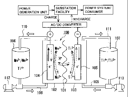
Redox flow batteries 100 according to the first reference embodiment and the
second to
third embodiments have similar basic structures, which are first described
with reference to Figs.
1 (I), 2 and 3. Redox flow battery 100 is representatively connected to a
power generation unit
(e.g., a solar photovoltaic power generator, a wind power generator, or a
common power plant)
and to a power system or a consumer through an AC/DC converter, charged with
the power
generation unit as a power supply source, and discharged to provide power to
the power system or
the consumer. To be charged and discharged, the following battery system
including redox flow
battery 100 and a circulation mechanism (tanks, ducts, pumps) for circulating
an electrolyte
through battery 100 is constructed.
Redox flow battery 100 includes a positive electrode cell 102 having a
positive electrode
104 therein, a negative electrode cell 103 having a negative electrode 105
therein, and a
membrane 101 separating cells 102 and 103 from each other, through which ions
permeate as
appropriate. Positive electrode cell 102 is connected to a tank 106 for a
positive electrode
electrolyte through ducts 108, 110. Negative electrode cell 103 is connected
to a tank 107 for a
negative electrode electrolyte through ducts 109, 111. Ducts 108, 109 include
pumps 112, 113
for circulating the electrolytes of the electrodes, respectively. In redox
flow battery 100, the
positive electrode electrolyte in tank 106 and the negative electrode
electrolyte in tank 107 are
supplied to positive electrode cell 102 (positive electrode 104) and negative
electrode cell 103
(negative electrode 105) through circulation, respectively, through ducts 108
to 111 and pumps
112, 113, to charge and discharge the battery through valence change reaction
of metal ions
serving as active materials in the electrolytes of both electrodes.
Redox flow battery 100 representatively has a form referred to as a cell
stack, which
includes a plurality of cells 102, 103 stacked therein. Cells 102, 103 are
representatively
structured with a cell frame including a bipolar plate (not shown) having
positive electrode 104
arranged on one surface and negative electrode 105 on the other surface, and a
frame (not shown)
having a liquid supply hole for supplying the electrolytes and a liquid
drainage hole for draining
the electrolytes, and formed on the periphery of the bipolar plate. By
stacking a plurality of cell
frames, the liquid supply holes and the liquid drainage holes form a fluid
path for the electrolytes,
-18-
CA 02748146 2011-10-18
which is connected to ducts 108 to 111 as appropriate. The cell stack is
structured by
successively and repeatedly stacking the cell frame, positive electrode 104,
membrane 101,
negative electrode 105, and the cell frame. A known structure may be used as
appropriate as a
basic structure of the redox flow battery system.
Particularly, in the redox flow battery according to the first reference
embodiment, the
positive electrode electrolyte contains a manganese ion, and the negative
electrode electrolyte
contains at least one type of metal ion selected from a titanium ion, a
vanadium ion, a chromium
ion, a zinc ion, and a tin ion (a titanium ion is shown as an example in Fig.
1 (I)). Redox flow
battery 100 according to the first reference embodiment uses the manganese ion
as the positive
electrode active material and the metal ion mentioned above as the negative
electrode active
material, and is operated such that the positive electrode electrolyte has an
SOC of not more than
90%. In this embodiment, it is preferable that the redox flow battery system
further include
control means for controlling an operating state such that the SOC is within
the specific range.
As will be described later, the SOC is determined from a charge time and a
theoretical charge
time. Thus, control means 200 may include, for example, input means 201 for
previously
inputting parameters (such as a charge current, a quantity of electricity of
the active material)
which are used for calculating the theoretical charge time as shown in Fig. 1
(II), charge time
operation means 202 for calculating the theoretical charge time from the input
parameters, storage
means 203 for storing various input values, timer means 204 for measuring the
charge time for
battery 100, SOC operation means 205 for operating the SOC from the measured
charge time and
the theoretical charge time obtained by operation, determination means 206 for
determining
whether or not the SOC is within the specific range, and instruction means 207
for indicating
continuation or termination of operation of battery 100 in order to adjust the
charge time for
battery 100 based on the results of the determination means. For such control
means, a computer
including a processor having the operation means and the like, and including
direct input means
210 such as a keyboard may be suitably used. Display means 211 such as a
monitor may also be
included.
-19-
CA 02748146 2011-10-18
Particularly, in the redox flow battery according to the second embodiment,
the positive
electrode electrolyte contains both of a manganese ion and a titanium ion, and
the negative
electrode electrolyte contains at least one type of metal ion selected from a
titanium ion, a
vanadium ion, a chromium ion, a zinc ion, and a tin ion (a titanium ion is
shown as an example in
Fig. 2). Redox flow battery 100 according to the second embodiment uses the
manganese ion as
the positive electrode active material and the metal ion mentioned above as
the negative electrode
active material.
Particularly, in the redox flow battery according to the third embodiment,
both of the
positive electrode electrolyte and the negative electrode electrolyte contain
both of a manganese
ion and a titanium ion, the manganese ion in the positive electrode
electrolyte serves as the
positive electrode active material, and the titanium ion in the negative
electrode electrolyte serves
as the negative electrode active material.
The electrolytes and operating conditions of the redox flow battery according
to the first
reference embodiment will be described below with reference to experimental
examples.
[First Experimental Example]
The redox flow battery system shown in Fig. 1 was structured, charged and
discharged
with an electrolyte containing a manganese ion for an active material as the
positive electrode
electrolyte, and relation between a state of charge (SOC) of the positive
electrode electrolyte and
a precipitation phenomenon was examined.
As the positive electrode electrolyte, an electrolyte having a manganese ion
(divalent)
concentration of 1M was prepared by dissolving manganese sulfate (divalent) in
a sulfuric acid
aqueous solution (H2SO4aq) having a sulfuric acid concentration of 4M. As the
negative
electrode electrolyte, an electrolyte having a vanadium ion (trivalent)
concentration of 1.7M was
prepared by dissolving vanadium sulfate (trivalent) in a sulfuric acid aqueous
solution (H2SO4aq)
having a sulfuric acid concentration of 1.75M.
-20-
CA 02748146 2011-08-08
110226-WO-00: 910722
A carbon felt was used for each electrode, and an anion exchange membrane was
used
for the membrane.
In this experiment, a small cell in which an electrode had an area of 9 cm2
was
made, 6 ml (6 cc) of the electrolyte was prepared for each electrode, and
charge and
discharge was performed with these electrolytes. Particularly, in this
experiment, a
battery voltage when switching takes place between charge and discharge, i.e.,
a
switching voltage was set as a maximum charge voltage, and the SOC of the
positive
electrode electrolyte upon completion of charge was varied by changing the
switching
voltage as shown in Table 1. Charge and discharge was performed with a
constant
current having a current density of 70 mA/cm2, and charge was switched to
discharge
when the switching voltage shown in Table 1 was reached. The SOC was
calculated as
indicated below, on the assumption that a quantity of conducted electricity
(integrated
value: Axh (time)) had entirely been used for charge (one-electron reaction:
Mn21---4
Mn3 + ej The SOC was measured using an initial charge time. In the first and
all
subsequent experimental examples, charge efficiency was almost 100%, and an
error
was considered to be small even on the assumption that the quantity of
conducted
electricity had entirely been used for charge.
Quantity of charged electricity (A = second) = charge time (t) x charge
current
(I)
Quantity of electricity of active material = mole number x Faraday constant =
volume x concentration x 96,485 (A = second/mol)
Theoretical charge time = quantity of electricity of active material/charge
current
(I)
State of charge = quantity of charged electricity/theoretical quantity of
charged
electricity
_ (charge time x current)/(theoretical charge time x current)
= charge time x theoretical charge time
A charge and discharge cycle was repeated three times under the above
-21-
CA 02748146 2011-08-08
110226-WO-00: 910722
conditions, and then presence of a precipitation was examined. The results are
shown
in Table 1.
[Table 1]
Switching voltage State of charge Presence of
(V) (%) Precipitation
1.70 14 No
1.80 47 No
1.82 70 No
1.84 90 No
1.85 104 Yes
1.9 139 Yes
2.0 148 Yes
2.1 159 Yes
As shown in Table 1, when the SOC was more than 90%, a precipitation was
generated even after three charge and discharge cycles, and it was difficult
to obtain
functionality of a battery after these cycles due to the precipitation. The
precipitation
was examined and found to be Mn02.
In contrast, when the SOC was not more than 90%, oxidation-reduction reaction
of divalent manganese ions and trivalent manganese ions occurred reversibly,
and
functionality of a battery could be obtained to a sufficient degree. When the
SOC was
near 90%, although a small amount of precipitation was observed, the battery
could be
used without any difficulty, and when the SOC was not more than 70%, a
precipitation
was not substantially observed. Further, by using the electrodes made of
carbon felt,
generated oxygen gas was substantially negligible.
It is thus shown that even in such redox flow battery using the positive
electrode
electrolyte containing a manganese ion as the positive electrode active
material,
generation of a precipitation of Mn02 can be effectively suppressed, and the
battery can
be charged and discharged well by being operated such that the positive
electrode
electrolyte has an SOC of not more than 90%. In particular, the vanadium-
manganese-
-22-
CA 02748146 2011-08-08
110226-WO-00: 910722
based redox flow battery shown in this experimental example can have a high
electromotive force of about 1.8V.
When chromium sulfate (trivalent), zinc sulfate (divalent) or tin sulfate
(tetravalent) are used instead of the vanadium sulfate (trivalent), generation
of a
precipitation can be suppressed by operating the battery such that the
positive electrode
electrolyte has an SOC of not more than 90% upon completion of charge.
[Second Experimental Example]
A redox flow battery system was structured, charged and discharged in the same
manner as the first experimental example, and battery properties (current
efficiency,
voltage efficiency, energy efficiency) were examined.
In this experiment, the negative electrode active material contained a metal
ion
different from that in the first experimental example. Specifically, as the
negative
electrode electrolyte, an electrolyte having a titanium ion (tetravalent)
concentration of
IM was prepared by dissolving titanium sulfate (tetravalent) in a sulfuric
acid aqueous
solution (H2SO4aq) having a sulfuric acid concentration of 3.6M. The positive
electrode electrolyte used was the same as that in the first experimental
example
(sulfuric acid concentration: 4M, manganese sulfate (divalent) was used,
manganese ion
(divalent) concentration: 1M). A carbon felt was used for each electrode, and
an anion
exchange membrane or a cation exchange membrane was used for the membrane.
As in the first experimental example, a small cell in which an electrode had
an
area of 9 cm2 was made, 6 ml (6 cc) of the electrolyte was prepared for each
electrode,
and charge and discharge was performed with these electrolytes and a constant
current
having a current density of 70 mA/cm2, as in the first experimental example.
In this
experiment, charge was terminated and switched to discharge when the switching
voltage reached 1.60V as shown in Fig. 4, such that the positive electrode
electrolyte
had an SOC of not more than 90% upon completion of charge.
As a result, although a small amount of precipitation (Mn02) was observed in
both cases where the anion exchange membrane and the cation exchange membrane
- 2 3 -
CA 02748146 2011-08-08
110226-WO-00: 910722
were used, it was confirmed that oxidation-reduction reaction of divalent
manganese
ions and trivalent manganese ions occurred reversibly, and functionality of a
battery
could be obtained without any difficulty as in the first experimental example,
as shown in
Fig. 4.
Further, for both cases where the anion exchange membrane was used and the
cation exchange membrane was used, current efficiency, voltage efficiency, and
energy
efficiency of charge and discharge described above were examined. Current
efficiency
is expressed as a quantity of discharged electricity (C)/a quantity of charged
electricity
(C), voltage efficiency is expressed as a discharge voltage (V)/a charge
voltage (V), and
energy efficiency is expressed as current efficiency x voltage efficiency.
Each
efficiency was calculated by measuring an integrated value of a quantity of
conducted
electricity (Axh (time)), an average voltage during charge and an average
voltage during
discharge, and using these measured values. Further, the SOC was determined in
the
same manner as the first experimental example.
As a result, when the anion exchange membrane was used, the current efficiency
was 97.8%, the voltage efficiency was 88.6%, the energy efficiency was 86.7%,
a
discharged capacity was 12.9 min (ratio to theoretical discharged capacity:
84%), and
the SOC was 86% (13.2 min), and when the cation exchange membrane was used,
the
current efficiency was 98.2%, the voltage efficiency was 85.1%, the energy
efficiency
was 83.5%, a discharged capacity was 12.9 min (ratio to theoretical discharged
capacity: 84%), and the SOC was 90% (14 min), and it was confirmed that
excellent
battery properties were obtained in both cases.
[Third Experimental Example]
Solubility of a manganese ion (divalent) in sulfuric acid (H2SO4) was
examined.
The results are shown in Fig. 5. As shown in Fig. 5, it can be seen that the
solubility of
a manganese ion (divalent) decreases as sulfuric acid concentration increases,
and the
solubility is 0.3M when the sulfuric acid concentration is 5M. Conversely, it
can be
seen that high solubility of 4M is obtained in an area of low sulfuric acid
concentration.
-24-
CA 02748146 2011-08-08
110226-WO-00: 910722
The results show that, in order to increase manganese ion concentration in an
electrolyte,
particularly in order to obtain a practically desired concentration of not
less than 0.3M,
when a sulfuric acid aqueous solution is used as a solvent for the
electrolyte, it is
preferable to have a low sulfuric acid concentration of less than 5M.
[Fourth Experimental Example]
A vanadium-manganese-based redox flow battery system was structured,
charged and discharged in the same manner as the first experimental example,
and a
precipitation state was examined.
In this experiment, as the positive electrode electrolyte, the following three
types
of positive electrode electrolytes (I) to (III) having different sulfuric acid
concentrations
and manganese ion (divalent) concentrations were prepared by dissolving
manganese
sulfate (divalent) in a sulfuric acid aqueous solution (H2SO4aq). As the
negative
electrode electrolyte, an electrolyte having a vanadium ion (trivalent)
concentration of
1.7M was prepared by dissolving vanadium sulfate (trivalent) in a sulfuric
acid aqueous
solution (H2SO4aq) having a sulfuric acid concentration of 1.75M. The
conditions
other than the electrolytes were the same as those for the redox flow battery
according
to the first experimental example (membrane: anion exchange membrane,
electrode:
carbon felt, area of electrode: 9 em2, amount of each electrolyte: 6 ml).
(I) Sulfuric acid concentration : manganese ion (divalent) concentration = 1M
:
4M
(II) Sulfuric acid concentration : manganese ion (divalent) concentration = 2M
:
3M
(III) Sulfuric acid concentration : manganese ion (divalent) concentration =
4M :
1.5M
Charge and discharge was performed with a constant current having a current
density of 70 mA/cm2, and repeatedly performed such that charge was terminated
and
switched to discharge when a battery voltage (switching voltage) reached 2. 1
OV, as
shown in Fig. 6.
-25-
CA 02748146 2011-08-08
110226-WO-00: 910722
As a result, when the positive electrode electrolytes (I) and (II) were used,
the
SOC was not more than 90%, and although a small amount of precipitation (MnO2)
was
observed, charge and discharge could be performed well without any difficulty,
as will
be described later. In contrast, when the positive electrode electrolyte (III)
was used,
the SOC was more than 90% (122%), and a large amount of precipitated Mn02 was
observed after a few cycles. As such, it can be seen that a different liquid
composition
results in a different SOC even with the same switching voltage. Thus, when
the
battery is operated over a long period of time with the positive electrode
electrolyte
having an SOC of more than 90%, measures to suppress precipitation of Mn02
need to
be taken.
Battery properties of the redox flow battery used in this experiment were
examined in the same manner as the second experimental example. The redox flow
battery using the positive electrode electrolyte (I) had a current efficiency
of 84,2%, a
voltage efficiency of 81.4%, an energy efficiency of 68.6%, a discharged
capacity of
18.2 min (ratio to theoretical discharged capacity: 30%), and an SOC of 44%
(26.8 min),
the redox flow battery using the positive electrode electrolyte (II) had a
current
efficiency of 94.2%, a voltage efficiency of 87.6%, an energy efficiency of
82.6%, a
discharged capacity of 25.7 min (ratio to theoretical discharged capacity:
56%), and an
SOC of 60% (27.4 min), and the redox flow battery using the positive electrode
electrolyte (III) had, when measured in an early stage of operation, a current
efficiency
of 97.1%, a voltage efficiency of 89.4%, an energy efficiency of 86.7%, a
discharged
capacity of 25.6 min (ratio to theoretical discharged capacity: 111%), and an
SOC of
122% (28.1 min). It can be seen that excellent battery properties are attained
when the
positive electrode electrolytes (I), (II) are used. In addition, it can be
said from these
results that the battery properties tend to be better with increase in
sulfuric acid
concentration, and with decrease in manganese ion (divalent) concentration
when the
concentration is not less than 0.3M and not more than 5M.
[Fifth Experimental Example]
-26-
CA 02748146 2011-08-08
110226-WO-00: 910722
A vanadium-manganese-based redox flow battery system was structured,
charged and discharged in the same manner as the fourth experimental example,
and a
precipitation state was examined.
In this experiment, three types of positive electrode electrolytes having a
manganese ion (divalent) concentration fixed to IM and different sulfuric acid
concentrations 2M, 3M, 4M (referred to as electrolytes (I), (II), (III),
respectively) were
prepared, and the other conditions were the same as those in the fourth
experimental
example (sulfuric acid concentration in negative electrode electrolyte: 1.75M,
vanadium
ion (trivalent) concentration in negative electrode electrolyte: 1.7M,
membrane: anion
exchange membrane, electrode: carbon felt, area of electrode: 9 cm2, amount of
each
electrolyte: 6 ml). Charge and discharge was repeatedly performed under the
same
conditions as those in the fourth experimental example (switching voltage: 2.
IV, current
density: 70 mA/cm2). Figs. 7 show relations between a cycle time of charge and
discharge and the battery voltage when the electrolytes (I) to (III) were
used.
As a result, the redox flow battery using the electrolytes (I) and (II) that
could
be operated such that the SOC was not more than 90% could be charged and
discharged
well without any difficulty although a small amount of precipitation (Mn02)
was
observed, as will be described later. In contrast, the redox flow battery
using the
electrolyte (III) having an SOC of more than 90% could be operated for about
three
cycles, but a large amount of precipitation was observed after a few cycles of
operation,
resulting in difficulty in continuing the operation.
Battery properties of the redox flow battery used in this experiment were
examined in the same manner as the second experimental example. The redox flow
battery using the electrolyte (I) had a current efficiency of 86. 1%, a
voltage efficiency of
84.4%, an energy efficiency of 72.6%, a discharged capacity of 7.3 min (ratio
to
theoretical discharged capacity: 48%), and an SOC of 63% (9.7 min), and the
redox
flow battery using the electrolyte (II) had a current efficiency of 89.1 %, a
voltage
efficiency of 87.3%, an energy efficiency of 77.7%, a discharged capacity of
11.8 min
-27-
CA 02748146 2011-08-08
110226-WO-00: 910722
(ratio to theoretical discharged capacity: 77%), and an SOC of 90% (13.7 min),
which
indicated excellent battery properties. In contrast, the redox flow battery
using the
electrolyte (III) had, when measured in an early stage of operation, a current
efficiency
of 96.9%, a voltage efficiency of 88.5%, an energy efficiency of 85.7%, a
discharged
capacity of 19.3 min (ratio to theoretical discharged capacity: 126%), and an
SOC of
159% (24.3 min).
Here, a theoretical discharged capacity (discharge time) of one-electron
reaction
in an electrolyte having a volume of 6 ml and a manganese ion (divalent)
concentration
of IM is 15.3 minutes. In contrast, when the electrolyte (III) having the
sulfuric acid
concentration of 4M was used in this experiment, a discharged capacity of 19.3
minutes
was surprisingly obtained. The reason for this increase in discharged capacity
may be
because Mn02 (tetravalent) generated through disproportionation reaction was
reduced
to a manganese ion (divalent) through two-electron reaction. It is thus
considered that
the phenomenon resulting from two-electron reaction (tetravalent -> divalent)
can be
utilized to increase energy density, thereby obtaining a higher battery
capacity.
The redox flow battery according to the second embodiment will be described
below with reference to an experimental example.
[Sixth Experimental Example]
The redox flow battery system shown in Fig. 2 according to the second
embodiment was structured, charged and discharged with an electrolyte
containing both
a manganese ion and a titanium ion as the positive electrode electrolyte, and
a
precipitation state and battery properties were examined.
In this experiment, as the positive electrode electrolyte, two types of
sulfuric
acid aqueous solutions (H2SO4aq) having different sulfuric acid concentrations
were
prepared, and manganese sulfate (divalent) and titanium sulfate (tetravalent)
were
dissolved in each of the sulfuric acid aqueous solutions, to prepare
electrolytes having a
manganese ion (divalent) concentration of 1M and a titanium ion (tetravalent)
concentration of IM. The positive electrode electrolyte having a sulfuric acid
-28-
CA 02748146 2011-08-08
110226-WO-00: 910722
concentration of 1M will be referred to as an electrolyte (I), and the
positive electrode
electrolyte having a sulfuric acid concentration of 2.5M will be referred to
as an
electrolyte (II). As the negative electrode electrolyte, an electrolyte having
a vanadium
ion (trivalent) concentration of 1.7M was prepared by dissolving vanadium
sulfate
(trivalent) in a sulfuric acid aqueous solution (H2SO4aq) having a sulfuric
acid
concentration of 1.75M. A carbon felt was used for each electrode, and an
anion
exchange membrane was used for the membrane.
In this experiment, a small cell in which an electrode had an area of 9 cm2
was
made, 6 ml (6 cc) of the electrolyte was prepared for each electrode, and
charge and
discharge was performed with these electrolytes. Particularly, in this
experiment, a
battery voltage when switching takes place between charge and discharge, i.e.,
a
switching voltage was set as a maximum charge voltage, and the switching
voltage was
set to 2.1V in both cases where the electrolytes (1) and (II) were used.
Charge and
discharge was performed with a constant current having a current density of 70
mA/cm2,
and charge was switched to discharge when the switching voltage was reached.
For the redox flow battery using the electrolytes (I), (II), the SOCs in an
early
stage of charge time were measured. The SOC was calculated in the same manner
as
the first experimental experiment, on the assumption that a quantity of
conducted
electricity (integrated value: Axh (time)) had entirely been used for charge
(one-electron
reaction: Mn" --> Mn3+ + e ). In this experiment, charge efficiency was almost
100%,
and an error was considered to be small even on the assumption that the
quantity of
conducted electricity had entirely been used for charge.
Figs. 8 (I) and 8 (II) show relations between the cycle time of charge and
discharge and the battery voltage when the electrolytes (I) and (II) were
used,
respectively. The redox flow battery using the electrolyte (I) had an SOC of
118% (18
min), and the redox flow battery using the electrolyte (II) had an SOC of
146%. It was
confirmed that, even if charge was performed until after the positive
electrode
electrolyte had an SOC of more than 100%, and further more than 130% upon
-29-
CA 02748146 2011-08-08
110226-WO-00: 910722
completion of charge in this manner, a precipitation (Mn02) was not
substantially
observed at all, and oxidation-reduction reaction of divalent manganese ions
and
trivalent manganese ions occurred reversibly, allowing functionality of a
battery without
any difficulty. It is assumed from these results that by containing a titanium
ion in the
positive electrode electrolyte, Mn" is stabilized, and any generated Mn02 is
not
precipitated but exists stably in the electrolyte, acting on charge and
discharge reaction.
Further, for both cases where the electrolytes (I) and (II) were used, current
efficiency, voltage efficiency, and energy efficiency of charge and discharge
described
above were examined. The current efficiency, voltage efficiency, and energy
efficiency
were calculated in the same manner as the second experimental example.
As a result, when the electrolyte (I) was used, the current efficiency was
98.4%,
the voltage efficiency was 85.6%, and the energy efficiency was 84.2%, and
when the
electrolyte (II) was used, the current efficiency was 98.3%, the voltage
efficiency was
87.9%, and the energy efficiency was 86.4%, and it was confirmed that
excellent battery
properties were obtained in both cases.
Here, a theoretical discharged capacity (discharge time) of one-electron
reaction
in an electrolyte having a volume of 6 ml and a manganese ion (divalent)
concentration
of 1 M is 15.3 minutes, as described above. In contrast, when the electrolytes
(I) and
(II) were used, the discharged capacities were 16.8 min, 19.7 min,
respectively, which
correspond to 110%, 129% with respect to the theoretical discharged capacity,
respectively. The reason for this increase in discharged capacity may be
because MnO2
(tetravalent) generated during charge was reduced to a manganese ion
(divalent)
through two-electron reaction. It is thus considered that the phenomenon
resulting
from two-electron reaction (tetravalent --> divalent) can be utilized as
described above
to increase energy density, thereby obtaining a higher battery capacity.
It is thus shown that even in such redox flow battery using the positive
electrode
electrolyte containing a manganese ion as the positive electrode active
material,
generation of a precipitation of Mn02 can be effectively suppressed, and the
battery can
-30-
CA 02748146 2011-08-08
110226-WO-00: 910722
be charged and discharged well by containing a titanium ion. In particular,
the
vanadium-manganese-based redox flow battery shown in this experimental example
can
have a high electromotive force of about 1. 8V. Further, by using the
electrodes made
of carbon felt, generated oxygen gas was substantially negligible.
When titanium sulfate (tetravalent), chromium sulfate (trivalent), zinc
sulfate
(divalent) or tin sulfate (tetravalent) are used instead of the vanadium
sulfate (trivalent)
above, generation of a precipitation can be suppressed by containing both a
manganese
ion and a titanium ion (tetravalent) in the positive electrode electrolyte.
The redox flow battery according to the third embodiment will be described
below with reference to an experimental example.
[Seventh Experimental Example]
The redox flow battery system shown in Fig. 3 according to the third
embodiment was structured, charged and discharged with an electrolyte
containing both
a manganese ion and a titanium ion as both of the positive electrode
electrolyte and the
negative electrode electrolyte, and a precipitation state and battery
properties were
examined.
In this experiment, for both of the positive electrode electrolyte and the
negative
electrode electrolyte to contain the same types of metal ions, an electrolyte
having a
manganese ion (divalent) concentration of 1.2M and a titanium ion
(tetravalent)
concentration of 1.2M was prepared by dissolving manganese sulfate (divalent)
and
titanium sulfate (tetravalent) in a sulfuric acid aqueous solution (H2SO4aq)
having a
sulfuric acid concentration of 2M. A carbon felt was used for each electrode,
and an
anion exchange membrane was used for the membrane.
In this experiment, a small cell in which an electrode had an area of 9 cm2
was
made, 6 ml (6 cc) of the electrolyte was prepared for each electrode in
Embodiment (I),
6 ml (6 cc) of the positive electrode electrolyte and 9 ml (9 cc) of the
negative electrode
electrolyte were prepared in Embodiments (II) and (III), and charge and
discharge was
performed with these electrolytes. Particularly, in this experiment, a battery
voltage
-31-
CA 02748146 2011-08-08
110226-WO-00: 910722
when switching takes place between charge and discharge, i.e., a switching
voltage was
set as a maximum charge voltage, and the switching voltage was set to 1.7V in
Embodiments (I) to (III). Charge and discharge was performed with a constant
current
having a current density of 50 mA/cm2 in Embodiments (I) and (III) and with a
constant
current having a current density of 70 mA/cm2 in Embodiment (II), and charge
was
switched to discharge when the switching voltage was reached.
For the redox flow battery in Embodiments (I), (II) and (III), the SOCs in an
early stage of charge time were measured. The SOC was calculated in the same
manner as the first experimental experiment, on the assumption that a quantity
of
conducted electricity (integrated value: Axh (time)) had entirely been used
for charge
(one-electron reaction: Mn21 -> Mn31 + e-). In this experiment, charge
efficiency was
almost 100%, and an error was considered to be small even on the assumption
that the
quantity of conducted electricity had entirely been used for charge.
Figs. 9 (I), 9 (II) and 9 (III) show relations between the cycle time of
charge and
discharge and the battery voltage in Embodiments (I), (II) and (III),
respectively. The
SOC in Embodiment (I) was 101% (26 min), and by making the amount of negative
electrode electrolyte higher than the amount of positive electrode electrolyte
to increase
the SOC, the SOC in Embodiment (II) was 110% (20.2 min). Further, by
decreasing
the current density from 70 mA/cm2 to 50 mA/cm2 to increase the SOC with the
same
amounts of electrolytes of both electrodes as in Embodiment (II), the SOC in
Embodiment (III) was 139% (35.6 min). It was confirmed that, even if charge
was
performed until after the positive electrode electrolyte had an SOC of more
than 100%,
and further more than 130% upon completion of charge in this manner, a
precipitation
(Mn02) was not substantially observed at all, and oxidation-reduction reaction
of
divalent manganese ions and trivalent manganese ions occurred reversibly,
allowing
functionality of a battery without any difficulty. It is assumed from these
results that by
containing a titanium ion in the positive electrode electrolyte, Mn31 is
stabilized, and any
generated Mn02 is not precipitated but exists stably in the electrolyte,
acting on charge
-32-
CA 02748146 2011-08-08
110226-WO-00: 910722
and discharge reaction.
Further, for Embodiments (I), (II) and (III), current efficiency, voltage
efficiency,
and energy efficiency of charge and discharge described above were examined.
The
current efficiency, voltage efficiency, and energy efficiency were calculated
in the same
manner as the second experimental example.
As a result, the current efficiency was 98.8%, the voltage efficiency was
88.9%,
and the energy efficiency was 87.9% in Embodiment (I), the current efficiency
was
99.8%, the voltage efficiency was 81.6%, and the energy efficiency was 81.4%
in
Embodiment (II), and the current efficiency was 99.6%, the voltage efficiency
was
85.3%, and the energy efficiency was 85.0% in Embodiment (III), and it was
confirmed
that excellent battery properties were obtained in all cases.
Here, a theoretical discharged capacity (discharge time) of one-electron
reaction
(Mn3+ + e = Mn2+) in an electrolyte having a volume of 6 ml and a manganese
ion
(divalent) concentration of 1.2M is 25.7 minutes (50 mA/cm2). In contrast, the
discharged capacities in Embodiments (I) to (III) were 24.2 min (50 mA/cm2),
20.1 min
(70 mA/cm2), and 33.5 min (50 mA/cm2), respectively. The reason for this
increase in
discharged capacity may be because Mn02 (tetravalent) generated during charge
was
reduced to a manganese ion (divalent) through two-electron reaction. It is
thus
considered that the phenomenon resulting from two-electron reaction
(tetravalent -*
divalent) can be utilized as described above to increase energy density,
thereby obtaining
a higher battery capacity.
It is thus shown that even in such redox flow battery using the positive
electrode
electrolyte containing a manganese ion as the positive electrode active
material,
generation of a precipitation of Mn02 can be effectively suppressed, and the
battery can
be charged and discharged well by containing a titanium ion. In particular,
the
titanium-manganese-based redox flow battery shown in this experimental example
can
have a high electromotive force of about 1.4V. Moreover, since the types of
metal
ions existing in the electrolytes of the positive and negative electrodes are
equal to each
-33-
CA 02748146 2011-08-08
110226-WO-00: 910722
other in this redox flow battery, excellent effects can be attained. Namely,
(1) battery
capacity decrease due to movement of the metal ions to a counter electrode
does not
substantially occur, (2) even if liquid transfer occurs to cause a difference
in amounts of
electrolytes of both electrodes, the difference can be readily corrected, and
(3) the
electrolytes can be readily produced. Further, by using the electrodes made of
carbon
felt, generated oxygen gas was substantially negligible.
The embodiments described above can be modified as appropriate without
departing from the substance of the present invention, and are not limited to
the
description provided above. For example, the manganese ion concentration and
the
titanium ion concentration in the positive electrode electrolyte, the acid
concentration in
the solvent of the positive electrode electrolyte, the type and concentration
of the metal
ion for the negative electrode active material, the type and concentration of
the solvent
in the electrolyte of each electrode, the material of the electrodes, the
material of the
membrane and the like can be modified as appropriate.
INDUSTRIAL APPLICABILITY
The redox flow battery according to the present invention can be suitably used
as
a large-capacity storage battery for stabilizing variations in power-
generation output,
storing surplus generated power, and load leveling for power generation of new
energy
such as solar photovoltaic power generation and wind power generation. The
redox
flow battery according to the present invention can also be suitably used as a
large-
capacity storage battery attached to a common power plant for voltage sag and
power
failure prevention and for load leveling.
DESCRIPTION OF THE REFERENCE SIGNS
100 redox flow battery; 101 membrane; 102 positive electrode cell; 103
negative
electrode cell; 104 positive electrode; 105 negative electrode; 106 tank for
positive
electrode electrolyte; 107 tank for negative electrode electrolyte; 108, 109,
110, 111
duct; 112, 113 pump; 200 control means; 201 input means; 202 charge time
operation
means; 203 storage means; 204 timer means; 205 SOC operation means; 206
-34-
CA 02748146 2011-08-08
110226-WO-00: 910722
determination means; 207 instruction means; 210 direct input means; 211
display means.
-35-