Note : Les descriptions sont présentées dans la langue officielle dans laquelle elles ont été soumises.
CA 02749764 2011-07-14
WO 2010/083308 PCT/US2010/021041
STIMULATION LEADS, DELIVERY SYSTEMS AND METHODS OF USE
CROSS-REFERENCES TO RELATED APPLICATIONS
[0001] This application claims priority under 35 U.S.C. 119(e) to U.S.
Provisional Patent
Application No. 61/144,690, entitled "Stimulation Lead, Delivery System and
Methods of Use",
filed January 14, 2009, and U.S. Provisional Patent Application No.
61/252,270, entitled "Strain
Relief Support for Lead Connection", filed October 16, 2009, both of which are
incorporated
herein by reference for all purposes.
STATEMENT AS TO RIGHTS TO INVENTIONS MADE UNDER
FEDERALLY SPONSORED RESEARCH AND DEVELOPMENT
[0002] NOT APPLICABLE
REFERENCE TO A "SEQUENCE LISTING," A TABLE, OR A COMPUTER
PROGRAM LISTING APPENDIX SUBMITTED ON A COMPACT DISK.
[0003] NOT APPLICABLE
BACKGROUND OF THE INVENTION
[0004] The application of specific electrical energy to the spinal cord for
the purpose of
managing pain has been actively practiced since the 1960s. It is known that
application of an
electrical field to spinal nervous tissue can effectively mask certain types
of pain transmitted
from regions of the body associated with the stimulated nervous tissue. Such
masking is known
as paresthesia, a subjective sensation of numbness or tingling in the
afflicted bodily regions.
Such electrical stimulation of the spinal cord, once known as dorsal column
stimulation, is now
referred to as spinal cord stimulation or SCS.
[0005] Figs. IA-1B illustrate conventional placement of an SCS system 10.
Conventional SCS
systems typically include an implantable power source or implantable pulse
generator (IPG) 12
and an implantable lead 14. Such IPGs 12 are similar in size and weight to
pacemakers and are
typically implanted in the buttocks of a patient P, as shown, or in the
abdominal wall, chest wall,
or under the arm. Using fluoroscopy, the lead 14 is implanted into the
epidural space E of the
spinal column and positioned against the dura layer D of the spinal cord S, as
illustrated in Fig.
1B.
-1-
CA 02749764 2011-07-14
WO 2010/083308 PCT/US2010/021041
[0006] Fig. 2 illustrates example conventional paddle leads 16 and
percutaneous leads 18.
Paddle leads 16 typically have the form of a slab of silicon rubber having one
or more electrodes
20 on its surface. Example dimensions of a paddle lead 16 are illustrated in
Fig. 3. Percutaneous
leads 18 typically have the form of a tube or rod having one or more
electrodes 20 extending
therearound. Example dimensions of a percutaneous lead 18 are illustrated in
Fig. 4.
[0007] Paddle leads 16 and percutaneous leads 18 are positioned within the
epidural space E of
the spinal column by different methods due to their size and shape.
Percutaneously leads 18 are
positioned with the use of an epidural needle. Referring to Fig. 5, an
epidural needle 22 is
inserted through the skin (not shown) and advanced between adjacent vertebrae
VI, V2 so that it
penetrates the epidural space. Thus, a conduit is formed from outside of the
body to the epidural
space. The lead 18 is then advanced through the needle 22 and into the
epidural space. The lead
18 is typically advanced in an antegrade fashion up the midline of the spinal
column until it
reaches the area of the spinal cord that, when electrically stimulated,
produces a tingling
sensation (paresthesia) that covers the patient's painful area. To locate this
area, the lead is
moved and/or turned on and off while the patient provides feedback about
stimulation coverage.
Often, inadequate stimulation is obtained and the lead may be repositioned
multiple times before
adequate coverage is received. Because the patient participates in this
operation and directs the
operator to the correct area of the spinal cord, the procedure is performed
under monitored
anesthesia care.
[0008] Conventional paddle leads 16 are too large to fit through an epidural
needle. Therefore,
implantation of paddle leads 16 typically involves a mini laminotomy. A
laminotomy is a
neurosurgical procedure that removes part of a lamina of the vertebral arch.
An incision is
typically made slightly below the spinal cord segment to be stimulated. The
laminotomy creates
an opening 24 in the bone large enough to pass one or more paddle leads 16
through. Fig. 6
illustrates a mini laminotomy with a paddle lead 16 inserted therethrough so
that the stimulating
portion of the lead 16 resides against the dura layer D of the spinal cord S.
The target area for
stimulation usually has been located before this procedure during a spinal
cord stimulation trial
with percutaneous leads 18.
[0009] As with any surgery, surgical placement of stimulation leads is a
serious procedure and
should be treated as such. A variety of complications may result, including
complications with
the anesthesia medication, deep vein thrombosis (DVT), nerve damage, and
infection, to name a
few. Thus, less invasive procedures are desired. Such procedures should be
effective in treating
pain while minimizing complications, cost and debilitation. At least some of
these objectives
will be met by the present invention.
-2-
CA 02749764 2011-07-14
WO 2010/083308 PCT/US2010/021041
BRIEF SUMMARY OF THE INVENTION
[0010] The present invention provides devices, systems and methods for
accessing and treating
anatomies associated with a variety of conditions while minimizing possible
complications and
side effects. This is achieved by directly neuromodulating a target anatomy
associated with the
condition while minimizing or excluding undesired neuromodulation of other
anatomies.
Typically, this involves stimulating portions of neural tissue of the central
nervous system,
wherein the central nervous system includes the spinal cord and the pairs of
nerves along the
spinal cord which are known as spinal nerves. In particular, some embodiments
of the present
invention are used to selectively stimulate portions of the spinal nerves,
particularly one or more
dorsal root ganglions (DRGs), to treat chronic pain while causing minimal
deleterious side
effects such as undesired motor responses. Such stimulation is typically
achieved with the use of
a lead having at least one electrode thereon. The lead is advanced through the
patient anatomy
so that the at least one electrode is positioned on, near or about the target
anatomy. A variety of
leads, delivery devices and methods are thus provided.
[0011] In a first aspect of the present invention, a system is provided for
positioning a lead
near a spinal nerve, the system comprising a lead comprising a shaft having at
least one electrode
disposed thereon, and a sheath having a curved distal end, wherein the sheath
is configured to
extend over the shaft of the lead causing the lead to bend. The sheath has an
outer diameter
which allows advancement through an introducing needle into an epidural space
of a spinal
column and a stiffness which allows advancement along the epidural space to a
position wherein
the curved distal end of the sheath directs the lead toward the spinal nerve,
and wherein
withdrawal of the sheath positions the lead near the spinal nerve.
[0012] In some embodiments, the introducing needle has an inner diameter of
less than or
equal to approximately 0.067 inches. Typically, a 14 gauge needle has an inner
diameter of
0.067 inches. In other embodiments, the sheath has a minimum stiffness of
approximately 0.65
lbs-in2. The sheath may be comprised of a variety of materials, such as
polyimide or
polyetheretherketone. In some embodiments, the lead has a shaped distal tip,
wherein the sheath
is configured to extend over the shaft of the lead until a portion of the
distal end abuts the shaped
distal tip of the lead resisting further advancement of the sheath.
Optionally, the distal tip of the
lead provides an atraumatic cover for the distal end of the sheath.
[0013] In some embodiments, the lead includes a stylet lumen extending at
least partially
therethrough, wherein the system includes a stylet configured to be positioned
within the stylet
lumen of the lead so that advancement of the stylet and withdrawal of the
sheath positions the
lead near the spinal nerve. In such embodiments, the stylet may have a curved
distal end,
-3-
CA 02749764 2011-07-14
WO 2010/083308 PCT/US2010/021041
wherein the positioning the curved distal end of the sheath over the lead
bends the lead along a
first curvature toward the spinal nerve and wherein advancement of the lead
and stylet therein
beyond the sheath bends the lead along a second curvature so that the lead
extends from the
spinal column along a nerve root angulation. In some instances, the nerve root
angulation is
equal to or less than 90 degrees. And in some instances, the nerve root
angulation is equal to or
less than 45 degrees. In some embodiments, the distal end of the stylet is
curved having a
primary curve and a secondary curve.
[00141 In some embodiments, the system further comprising an additional sheath
having a
distal end, wherein the additional sheath is configured to pass within the
sheath so that its distal
end extends beyond the curved distal end of the sheath. The distal end of the
additional sheath
may be curved so that positioning the curved distal end of the sheath over the
lead bends the lead
along a first curvature toward the spinal nerve and wherein advancement of the
curved distal end
of the additional sheath beyond the curved distal end of the sheath bends the
lead along a second
curvature toward a nerve root angulation. Or the distal end of the additional
sheath may be
substantially straight so that positioning the curved distal end of the sheath
over the lead bends
the lead along a first curvature toward the spinal nerve and wherein
advancement of the curved
distal end of the additional sheath beyond the curved distal end of the sheath
directs the lead in a
substantially straight direction toward the spinal nerve.
[0015] In a second aspect of the present invention, a system is provided for
positioning a lead
near a spinal nerve, the system comprising a lead comprising a shaft having a
stylet lumen
extending at least partially therethrough and at least one electrode disposed
thereon, a sheath
having a curved distal end, wherein the sheath is configured to extend over
the shaft of the lead
causing the lead to bend, and a stylet configured to be positioned within the
stylet lumen of the
lead. The sheath is advanceable through an introducing needle into an epidural
space of the
spinal column and along the epidural space to a position wherein the curved
distal end of the
sheath directs the lead toward the spinal nerve, and wherein advancement of
the stylet positions
the lead near the spinal nerve.
[00161 In some embodiments, the stylet has a substantially straight distal
end. In other
embodiments, the stylet has a curved distal end, wherein the positioning the
curved distal end of
the sheath over the lead bends the lead along a first curvature toward the
spinal nerve and
wherein advancement of the lead and stylet therein beyond the sheath bends the
lead along a
second curvature so that the lead extends from the spinal column along a nerve
root angulation.
In some instances, the nerve root angulation is equal to or less than 90
degrees. In some
-4-
CA 02749764 2011-07-14
WO 2010/083308 PCT/US2010/021041
instances, the nerve root angulation is equal to or less than 45 degrees. In
some embodiments,
the distal end of the stylet is curved having a primary curve and a secondary
curve.
[0017] In a third aspect of the present invention, a system is provided for
accessing a nerve
root which extends from a spinal column along a nerve root sleeve angulation,
the system
comprising a lead comprising a shaft having a stylet lumen extending at least
partially
therethrough and at least one electrode disposed thereon, a sheath having a
curved distal end,
wherein the sheath is configured to extend over the shaft of the lead, and a
stylet having a curved
distal end, wherein the stylet is configured to be positioned within the
stylet lumen of the lead.
The lead is configured to be positioned along the spinal column, wherein
positioning of the
curved distal end of the sheath over the lead bends the lead along a first
curvature toward the
nerve root and wherein advancement of the lead and the stylet therein beyond
the sheath bends
the lead along a second curvature so that the lead extends from the spinal
column along the nerve
root sleeve angulation.
[0018] In some embodiments, the sheath is configured to be advanced through an
introducing
needle configured to access an epidural space of the spinal column. In some
embodiments, the
introducing needle has an inner diameter of less than or equal to
approximately 0.067 inches. In
some instances, the nerve root angulation is equal to or less than 90 degrees.
In some instances,
the angulation is equal to or less than 45 degrees. In some embodiments, the
distal end of the
sheath is curved having an angle in the range of approximately 80 to 165
degrees. In other
embodiments, the distal end of the stylet is curved having a primary curve and
a secondary
curve. Optionally, the primary curve may have an arch shape of approximately
180 degrees.
Optionally, the secondary curve may be proximal and adjacent to the primary
curve. Optionally,
the secondary curve may have a larger radius of curvature than the primary
curve. In some
embodiments, the lead has a closed-end distal tip having a shape which resists
advancement of
the sheath over the distal tip. Optionally, the shape may comprise a ball
shape.
[0019] In a fourth aspect of the present invention, a system is provided
comprising a lead
comprising a shaft having at least one electrode and a shaped distal tip, and
a sheath having a
distal end, wherein the sheath is sized and configured to be advanced over the
shaft of the lead
until a portion of its distal end abuts the shaped distal tip of the lead
resisting further
advancement of the sheath. In some embodiments, the shaped distal tip has a
ball shape. In
other embodiments, the lead is sized to fill an inner diameter of the sheath
so as to resist kinking
of the sheath. In other embodiments, the shaped distal tip of the lead
provides an atraumatic
cover for the distal end of the sheath. Typically, the sheath is sized to be
advanced through an
introducing needle configured to access an epidural space of the spinal
column. Such an
-5-
CA 02749764 2011-07-14
WO 2010/083308 PCT/US2010/021041
introducing needle may have a variety of inner diameters, particularly an
inner diameter of less
than or equal to approximately 0.067 inches.
[0020] In some embodiments, the distal end of the sheath has a curve, wherein
the sheath
bends the lead therein along the curve. In some embodiments, the sheath is
comprised of a
thermoset material. In some embodiments, the sheath is comprised of a
unidurometer material.
Optionally, the sheath may be at least partially radiopaque, such as loaded
with radiopaque
material. Or, the sheath may include at least one radiopaque marker.
[0021] In a fifth aspect of the present invention, a system is provided for
accessing a spinal
nerve comprising a lead comprising a shaft having at least one electrode
disposed thereon, a first
sheath having a curved distal end, wherein the first sheath is configured to
extend over the shaft
of the lead, and a second sheath extending through the first sheath, wherein
the additional sheath
is configured to pass within the sheath so that its distal end extends beyond
the distal end of the
first sheath. The first sheath has an outer diameter which allows advancement
through an
introducing needle into an epidural space of a spinal column, wherein the
first and second
sheaths together have a stiffness which allows advancement along the epidural
space to a
position wherein the distal ends of the first and second sheaths direct the
lead toward the spinal
nerve.
[0022] In some embodiments, distal end of the second sheath is curved so that
positioning the
curved distal end of the first sheath over the lead bends the lead along a
first curvature toward the
spinal nerve and wherein advancement of the curved distal end of the second
sheath beyond the
curved distal end of the first sheath bends the lead along a second curvature
toward a nerve root
angulation. In other embodiments, the distal end of the additional sheath is
substantially straight
so that positioning the curved distal end of the first sheath over the lead
bends the lead along a
first curvature toward the spinal nerve, wherein advancement of the curved
distal end of the
second sheath beyond the curved distal end of the first sheath directs the
lead in a substantially
straight direction toward the spinal nerve.
[0023] In some embodiments, the system further comprising a curved stylet
positionable
within the lead, wherein advancement of the lead and stylet therein beyond the
second sheath
bends the lead along a second curvature so that the lead extends from the
spinal column along a
nerve root angulation. Optionally, the system further comprises a control hub
connectable with a
proximal end of the first sheath and a proximal end of the second sheath,
wherein manipulation
of the control hub moves the first or second sheath in relation to each other.
In some
embodiments, the control hub includes a limiter, wherein the limiter limits
the movement of the
-6-
CA 02749764 2011-07-14
WO 2010/083308 PCT/US2010/021041
first or second sheath in relation to each other. In some embodiments,
manipulation of the
control hub is achievable with the use of one hand.
[0024] In a sixth aspect of the present invention, a stimulation lead is
provided comprising a
shaft comprising a tube having a distal end and a proximal end, a stylet tube
disposed within the
shaft, at least one electrode disposed near the distal end of the shaft, and
at least one conductor
cable extending from the at least one electrode toward the proximal end of the
shaft. The stylet
tube is fixedly coupled to the shaft at a first location near the distal end
and at a second location
proximal to the first location allowing for movement of the stylet tube within
the shaft
therebetween.
[0025] In some embodiments, the at least one conductor cable is disposed
between the stylet
tube and shaft, wherein the at least one conductor cable is fixedly coupled to
the shaft near the
proximal end and another location allowing for movement within the shaft
therebetween. In
some embodiments, the lead further comprises a tensile element fixedly coupled
to the shaft in at
least one location along the shaft. Optionally, the tensile element may have
freedom of
movement within the shaft outside of the at least one location. In some
embodiments, the tensile
element has multiple diameters. For example, the tensile element may have a
larger diameter
near its proximal end and neck down toward its distal end. In some
embodiments, the stylet tube
has a lubricious inner surface. Optionally, the stylet tube may be comprised
of polyimide.
[0026] In some embodiments, the shaft has a closed-end shaped distal tip. Such
a closed-end
shaped distal tip may have a ball shape. In some embodiments, at least a
portion of the distal end
of the shaft is configured to extend at least 180 degrees along the perimeter
of a half circle,
wherein the half circle has a radius of 0.25 inches. In some embodiments, the
lead is configured
to be advanced through an introducing needle configured to access an epidural
space of the
spinal column. Typically, the introducing needle has an inner diameter of less
than or equal to
approximately 0.067 inches.
[0027] Other objects and advantages of the present invention will become
apparent from the
detailed description to follow, together with the accompanying drawings.
BRIEF DESCRIPTION OF THE DRAWINGS
[0028] Figs. 1 A, 1 B, 2, 3, 4, 5, 6 illustrate prior art.
[0029] Fig. 7 illustrates an embodiment of a lead of the present invention
advanced through a
nerve root sleeve angulation so that at least one of its electrodes is
positioned within a clinically
effective distance of a target DRG.
-7-
CA 02749764 2011-07-14
WO 2010/083308 PCT/US2010/021041
[0030] Figs. 8A, 8B, 8C, 8D illustrate an embodiment of a lead and delivery
system, including
a sheath, stylet and introducing needle of the present invention.
[0031] Fig. 9 illustrates an embodiment of a sheath advanced over a shaft of a
lead with
internal stylet forming a first curvature.
[0032] Fig. 10 illustrates the lead with internal stylet of Fig. 9 extending
beyond the sheath
forming a second curvature.
[0033] Fig. 11 illustrates a method of accessing an epidural space with the
use of an
introducing needle.
[0034] Fig. 12 illustrates a method of attaching a syringe to the needle of
Fig. 11.
[0035] Fig. 13 illustrates a method of inserting a stylet, lead and sheath of
the present invention
through the needle of Fig. 11 into the epidural space.
[0036] Fig. 14 illustrates the distal end of the needle passed through the
ligamentum flavum
into the epidural space and the assembled sheath/lead/stylet of Fig. 13
emerging therefrom.
[0037] Fig. 15 illustrates advancing the assembled sheath/lead/stylet of Fig.
13 within the
epidural space toward a target DRG.
[0038] Fig. 16 illustrates the precurvature of the sheath directing the lead
laterally outwardly.
[0039] Fig. 17 illustrates the lead extending beyond the distal end of the
sheath of Fig. 16.
[0040] Fig. 18 illustrates a method of using the needle of Fig. 11 to position
an additional lead
within the epidural space.
[0041] Fig. 19 illustrates an additional assembled sheath/lead/stylet advanced
within the
epidural space toward another or second target DRG.
[0042] Fig. 20 illustrates the precurvature of the sheath of Fig. 19 directing
the lead laterally
outwardly.
[0043] Fig. 21 illustrates the lead advanced beyond the distal end of the
sheath of Fig. 20.
[0044] Fig. 22 illustrates a plurality of leads positioned within the epidural
space, each lead
stimulating a different DRG.
[0045] Fig. 23A illustrates an embodiment of a sheath of the present
invention.
[0046] Fig. 23B illustrates an embodiment of a hub having a locking cap and
injection port.
-8-
CA 02749764 2011-07-14
WO 2010/083308 PCT/US2010/021041
[0047] Figs. 24A, 24B, 24C, 24D, 24E illustrate an embodiment of a lead of the
present
invention.
[0048] Fig. 24F illustrates an embodiment lead of the present invention
comprising a multi-
lumen tubing.
[0049] Figs. 25, 26A-26B illustrate embodiments of a stylet of the present
invention.
[0050] Fig. 27 illustrates an embodiment of a system of the present invention
having multiple
sheaths.
[0051] Fig. 28 illustrates the system of Fig. 27 positioned within the
epidural space.
[0052] Figs. 29A, 29B, 29C illustrate a perspective view, a side view and a
front view,
respectively, of an embodiment of a control hub.
[0053] Fig. 30 illustrates a conventional stimulation system used to stimulate
tissues or organs
within the body.
[0054] Fig. 31 illustrates an embodiment of a strain relief support of the
present invention.
[0055] Fig. 32 illustrates a cross-section of the strain relief support,
including the support
member and the hub.
[0056] Figs. 33-36 illustrate insertion of the support member into the
proximal end of a lead
and detachment of the hub.
[0057] Fig. 37 illustrates the proximal end of the lead inserted into the
connection port of the
IPG.
DETAILED DESCRIPTION OF THE INVENTION
[0058] The present invention provides devices, systems and methods for
accessing and treating
anatomies associated with a variety of conditions, particularly conditions
that are associated with
or influenced by the nervous system. Examples of such conditions include pain,
itching,
Parkinson's Disease, Multiple Sclerosis, demylenating movement disorders,
spinal cord injury,
asthma, chronic heart failure, obesity and stroke (particularly acute
ischemia), to name a few.
Typically, the systems and devices are used to stimulate portions of neural
tissue of the central
nervous system, wherein the central nervous system includes the spinal cord
and the pairs of
nerves along the spinal cord which are known as spinal nerves. The spinal
nerves include both
dorsal and ventral roots which fuse in the intravertebral foramen to create a
mixed nerve which is
part of the peripheral nervous system. At least one dorsal root ganglion (DRG)
is disposed along
-9-
CA 02749764 2011-07-14
WO 2010/083308 PCT/US2010/021041
each dorsal root prior to the point of mixing. Thus, the neural tissue of the
central nervous
system is considered to include the dorsal root ganglions and exclude the
portion of the nervous
system beyond the dorsal root ganglions, such as the mixed nerves of the
peripheral nervous
system.
[0059] In some embodiments, the systems and devices of the present invention
are used to
stimulate one or more dorsal root ganglia, dorsal roots, dorsal root entry
zones, or portions
thereof. Accessing these areas is challenging, particularly from an antegrade
epidural approach.
Fig. 7 schematically illustrates portions of the anatomy in such areas. As
shown, each DRG is
disposed along a dorsal root DR and typically resides at least partially
between the pedicles PD
or within a foramen. Each dorsal root DR exits the spinal cord S at an angle
0. This angle 0 is
considered the nerve root sleeve angulation and varies slightly by patient and
by location along
the spinal column. The average nerve root angulation in the lumbar spine is
significantly less
than 90 degrees and typically less than 45 degrees. Therefore, accessing this
anatomy from an
antegrade approach involves making a sharp turn through, along or near the
nerve root sleeve
angulation. It may be appreciated that such a turn may follow the nerve root
sleeve angulation
precisely or may follow various curves in the vicinity of the nerve root
sleeve angulation.
[0060] Fig. 7 illustrates an embodiment of a lead 100 of the present invention
inserted
epidurally and advanced in an antegrade direction along the spinal cord S. The
lead 100, having
at least one electrode 102 thereon, is advanced through the patient anatomy so
that at least one of
the electrodes 102 is positioned on a target DRG. Such advancement of the lead
100 toward the
target DRG in this manner involves making a sharp turn along the angle 0. A
turn of this
severity is achieved with the use of delivery tools and design features of the
present invention
specific to such lead placement. In addition, the spatial relationship between
the nerve roots,
DRGs and surrounding structures are significantly influenced by degenerative
changes,
particularly in the lumbar spine. Thus, patients may have nerve root
angulations which differ
from the normal anatomy, such as having even smaller angulations necessitating
even tighter
turns. The present invention also accommodates these anatomies.
[0061] The devices, systems and methods of the present invention allow for
targeted treatment
of the desired anatomies. Such targeted treatment minimizes deleterious side
effects, such as
undesired motor responses or undesired stimulation of unaffected body regions.
This is achieved
by directly neuromodulating a target anatomy associated with the condition
while minimizing or
excluding undesired neuromodulation of other anatomies. For example, this may
include
stimulating the dorsal root ganglia, dorsal roots, dorsal root entry zones, or
portions thereof while
minimizing or excluding undesired stimulation of other tissues, such as
surrounding or nearby
-10-
CA 02749764 2011-07-14
WO 2010/083308 PCT/US2010/021041
tissues, portions of the ventral root and portions of the anatomy associated
with body regions
which are not targeted for treatment. Such stimulation is typically achieved
with the use of a
lead having at least one electrode thereon. The lead is advanced through the
patient anatomy so
that the at least one electrode is positioned on, near or about the target. In
some embodiments,
the lead and electrode(s) are sized and configured so that the electrode(s)
are able to minimize or
exclude undesired stimulation of other anatomies. In other embodiments, the
stimulation signal
or other aspects are configured so as to minimize or exclude undesired
stimulation of other
anatomies. In addition, it may be appreciated that stimulation of other
tissues are also
contemplated.
[00621 In most embodiments, neuromodulation comprises stimulation, however it
may be
appreciated that neuromodulation may include a variety of forms of altering or
modulating nerve
activity by delivering electrical or pharmaceutical agents directly to a
target area. For illustrative
purposes, descriptions herein will be provided in terms of stimulation and
stimulation
parameters, however, it may be appreciated that such descriptions are not so
limited and may
include any form of neuromodulation and neuromodulation parameters.
System Overview
[00631 Referring to Figs. 8A-8D, an embodiment of a lead 100 (Fig. 8A) and
delivery system
120, including a sheath 122 (Fig. 8B), stylet 124 (Fig. 8C) and introducing
needle 126 (Fig. 8D),
of the present invention is illustrated. In this embodiment, the lead 100
comprises a shaft 103
having a distal end 101 and four electrodes 102 disposed thereon. It may be
appreciated that any
number of electrodes 102 may be present, including one, two, three, four,
five, six, seven, eight
or more. In this embodiment, the distal end 101 has a closed-end distal tip
106. The distal tip
106 may have a variety of shapes including a rounded shape, such as a ball
shape (shown) or tear
drop shape, and a cone shape, to name a few. These shapes provide an
atraumatic tip for the
lead 100 as well as serving other purposes. The lead 100 also includes a
stylet lumen 104 which
extends toward the closed-end distal tip 106.
[00641 Fig. 8B illustrates an embodiment of a sheath 122 of the present
invention. The sheath
122 has a distal end 128 which is pre-curved to have an angle a, wherein the
angle a is in the
range of approximately 80 to 165 degrees. The sheath 122 is sized and
configured to be
advanced over the shaft 103 of the lead 100 until a portion of its distal end
128 abuts the distal
tip 106 of the lead 100, as illustrated in Fig. 9. Thus, the ball shaped tip
106 of this embodiment
also prevents the sheath 122 from extending thereover. Passage of the sheath
122 over the lead
100 causes the lead 100 to bend in accordance with the precurvature of the
sheath 122. Thus, the
-11-
CA 02749764 2011-07-14
WO 2010/083308 PCT/US2010/021041
sheath 122 assists in steering the lead 100 along the spinal column S and
toward a target DRG,
such as in a lateral direction. It may be appreciated that the angle a may
optionally be smaller,
such as less than 80 degrees, forming a U-shape or tighter bend.
[0065] Referring back to Fig. 8C, an embodiment of a stylet 124 of the present
invention is
illustrated. In this embodiment, the stylet 124 has a distal end 130 which is
pre-curved so that its
radius of curvature is in the range of approximately 0.1 to 0.5 inches. The
stylet 124 is sized and
configured to be advanced within the stylet lumen 104 of the lead 100.
Typically the stylet 124
extends therethrough so that its distal end 130 aligns with the distal end 101
of the lead 100.
Passage of the stylet 124 through the lead 100 causes the lead 100 to bend in
accordance with the
precurvature of the stylet 124. Typically, the stylet 124 has a smaller radius
of curvature, or a
tighter bend, than the sheath 122. Therefore, as shown in Fig. 10, when the
stylet 124 is
disposed within the lead 100, extension of the lead 100 and stylet 124 through
the sheath 122
bends or directs the lead 100 through a first curvature 123. Further extension
of the lead 100 and
stylet 124 beyond the distal end 128 of the sheath 122 allows the lead 100 to
bend further along a
second curvature 125. When approaching a target DRG, the second curvature
allows the
laterally directed lead 100 to now curve around toward the target DRG, such as
along the nerve
root angulation. This two step curvature allows the lead 100 to be
successfully positioned so that
at least one of the electrodes 102 is on, near or about the target DRG,
particularly by making a
sharp turn along the angle 0. In addition, the electrodes 102 are spaced to
assist in making such a
sharp turn.
[0066] Thus, the lead 100 does not require stiff or torqueable construction
since the lead 100 is
typically not torqued or steered by itself. The lead 100 is positioned with
the use of the sheath
122 and stylet 124 which direct the lead 100 through the two step curvature.
This eliminates the
need for the operator to torque the lead 100 and optionally the sheath 122
with multiple hands.
This also allows the lead 100 to have a lower profile and smaller diameter, as
well as a very soft
and flexible construction. This, in turn, minimizes erosion, irritation of the
neural tissue and
discomfort created by pressure on nerve tissue, such as the target DRG and/or
the nerve root,
once the lead 100 is implanted. In addition, such a soft and flexible lead 100
will minimize the
amount of force translated to the distal end of the lead 100 by body movement
(e.g. flexion,
extension, torsion).
[0067] Referring back to Fig. 8D, an embodiment of an introducing needle 126
is illustrated.
The introducing needle 126 is used to access the epidural space of the spinal
cord S. The needle
126 has a hollow shaft 127 and typically has a very slightly curved distal end
132. The shaft 127
is sized to allow passage of the lead 100, sheath 122 and stylet 124
therethrough. In some
-12-
CA 02749764 2011-07-14
WO 2010/083308 PCT/US2010/021041
embodiments, the needle 126 is 14 gauge which is typically the size of
epidural needles used to
place conventional percutaneous leads within the epidural space. However, it
may be
appreciated that other sized needles may also be used, particularly smaller
needles such as 15-18
gauge. Alternatively, non-standardized sized needles may be used.
[0068] The needle is atraumatic so as to not damage the sheath 122 when the
sheath 122 is
advanced or retracted. In some embodiments, the shaft 127 comprises a low
friction material,
such as bright hypotubing, made from bright steel (a product formed from the
process of drawing
hot rolled steel through a die to impart close dimensional tolerances, a
bright, scale free surface
and improved mechanical properties. Other materials include
polytetrafluoroethylene (PTFE)
impregnated or coated hypotubing. In addition, it may be appreciated that
needles having
various tips known to practitioners or custom tips designed for specific
applications may also be
used. The needle 126 also typically includes a luer fitting 134, such as a
Luer-LokTM fitting, or
other fitting near its proximal end. The luer fitting 134 is a female fitting
having a tabbed hub
which engages threads in a sleeve on a male fitting, such as a syringe. The
needle 126 may also
have a luer fitting on a side port, so as to allow injection through the
needle 126 while the sheath
122 is in the needle 126. In some embodiments, the luer fitting is tapered to
allow for easier
introduction of a curved sheath into the hollow shaft 127.
Delivery Methods
[0069] The above described delivery system 120 is used for epidural delivery
of the lead 100
of the present invention through the patient anatomy toward a target DRG.
Thus, embodiments
of epidural delivery methods of the present invention are described herein. In
particular, such
embodiments are described and illustrated as an antegrade approach. It may be
appreciated that,
alternatively, the devices and systems of the present invention may be used
with a retrograde
approach or a contralateral approach. Likewise, at least some of the devices
and systems may be
used with a transforaminal approach, wherein the DRG is approached from
outside of the spinal
column. Further, the target DRG may be approached through the sacral hiatus or
through a bony
structure such as a pedicle, lamina or other structure.
[0070] Epidural delivery involves accessing the epidural space. The epidural
space is accessed
with the use of the introducing needle 126, as illustrated in Fig. 11.
Typically, the skin is
infiltrated with local anesthetic such as lidocaine over the identified
portion of the epidural
space. The insertion point is usually near the midline M, although other
approaches may be
employed. Typically, the needle 126 is inserted to the ligamentum flavum and a
loss of
resistance to injection technique is used to identify the epidural space.
Referring to Fig. 12, a
-13-
CA 02749764 2011-07-14
WO 2010/083308 PCT/US2010/021041
syringe 140 is then attached to the needle 126. The syringe 140 may contain
air or saline.
Traditionally either air or saline has been used for identifying the epidural
space, depending on
personal preference. When the tip of the needle 126 enters a space of negative
or neutral
pressure (such as the epidural space), there will be a "loss of resistance"
and it will be possible to
inject through the syringe 140. At that point, there is now a high likelihood
that the tip of the
needle 126 has entered the epidural space. Further, a sensation of "pop" or
"click" may be felt as
the needle breaches the ligamentum flavum just before entering the epidural
space. In addition
to the loss of resistance technique, realtime observation of the advancing
needle 126 may be
achieved with a portable ultrasound scanner or with fluoroscopy. Likewise, a
guidewire may be
advanced through the needle 126 and observed within the epidural space with
the use of
fluoroscopy.
[0071] Once the needle 126 has been successfully inserted into the epidural
space, the syringe
140 is removed. The stylet 124 is inserted into the lead 100 and the sheath
122 is advanced over
the lead 100. The sheath 122 is positioned so that its distal end 128 is near
or against the distal
tip 106 of the lead 100 causing the lead 100 to follow the curvature of the
sheath 122. The stylet
124, lead 100 and sheath 122 are then inserted through the needle 126, into
the epidural space, as
illustrated in Fig. 13. Referring to Fig. 14, the distal end 132 of the needle
126 is shown passed
through the ligamentum flavum L and the assembled sheath 122/lead 100/stylet
124 is shown
emerging therefrom. The rigidity of the needle 126 straightens the more
flexible sheath 122 as it
passes therethrough. However, upon emergence, the sheath 122 is allowed to
bend along or
toward its precurvature as shown. In some embodiments, the shape memory of the
sheath 122
material allows the sheath 122 to retain more than 50% of its precurved shape
upon passing
through the needle 126. Such bending assists in steering of the lead 100
within the epidural
space. This is particularly useful when using a retrograde approach to
navigate across the
transition from the lumbar spine to the sacral spine. The sacrum creates a
"shelf' that resists
ease of passage into the sacrum. The precurved sheath 122 is able to more
easily pass into the
sacrum, reducing operating time and patient discomfort.
[0072] Referring to Fig. 15, the assembled sheath 122/lead 100/stylet 124 is
advanced within
the epidural space toward a target DRG. Steering and manipulation is
controlled proximally and
is assisted by the construction of the assembled components and the
precurvature of the sheath
122. In particular, the precurvature of the sheath 122 directs the lead 100
laterally outwardly,
away from the midline M of the spinal column. Fig. 16 illustrates the
assembled sheath 122/lead
1 00/stylet 124 advanced toward the target DRG with the precurvature of the
sheath 122 directing
the lead 100 laterally outwardly.
-14-
CA 02749764 2011-07-14
WO 2010/083308 PCT/US2010/021041
[0073] Referring to Fig. 17, the lead 100/stylet 124 is then advanced beyond
the distal end 128
of the sheath 122. In some embodiments, the lead 100 extends approximately 1-3
inches beyond
the distal end 128 of the sheath 122. However, the lead 100 may extend any
distance, such as
less than 1 inch, 0.25-3 inches, or more than 3 inches. Likewise, the sheath
122 may be retracted
to expose the lead 100, with or without advancement of the lead 100. This may
be useful when
advancement of the lead 100 is restricted, such as by compression of the
foraminal opening. The
curvature of the stylet 124 within the lead 100 causes the lead 100 to bend
further, along this
curvature. This allows the laterally directed lead 100 to now curve around
toward the target
DRG along the nerve root angulation. This two step curvature allows the lead
100 to be
successfully steered to position at least one of the electrodes 102 on, near
or about the target
DRG. In addition, the ball shaped distal tip 106 resists trauma to the anatomy
within the spinal
column, such as the dural sac, ligaments, blood vessels, and resists imparting
trauma to the DRG
as the lead 100 is manipulated and advanced into place. Once desirably
positioned, the sheath
122 and stylet 124 are typically removed leaving the lead 100 in place.
However, optionally, the
stylet 124 may be left within the lead 100 to stabilize the lead 100, to
assist in maintaining
position and to resist migration. The DRG may then be stimulated by providing
stimulation
energy to the at least one electrode 102, as illustrated by energy ring 140 in
Fig. 17. It may be
appreciated that multiple electrodes may be energized to stimulate the target
DRG. It may also
be appreciated that the electrodes may be energized prior to removal of the
stylet 124 and/or
sheath 122, particularly to ascertain the desired positioning of the lead 100.
It may further be
appreciated that the sheath 122 may be retracted to expose the lead 100 rather
than advancing the
lead 100 therethrough.
[0074] The same needle 126 can then be used to position additional leads
within the epidural
space. Again, a stylet 124 is inserted into a lead 100 and a sheath 122 is
advanced over the lead
100. The sheath 122 is positioned so that its distal end 128 is near or
against the distal tipl06 of
the lead 100 causing the lead 100 to follow the curvature of the sheath 122.
The assembled stylet
124/lead 100/sheath 122 is then inserted through the needle 126, into the
epidural space, as
illustrated in Fig. 18. The rigidity of the needle 126 straightens the more
flexible sheath 122 as it
passes therethrough. And, upon emergence, the sheath 122 is allowed to bend
along its
precurvature as shown. This creates an atraumatic exit of the stylet 124/lead
100/sheath 122 out
of the needle 126 since such curvatures resist any directed force into the
dura layer of the spinal
cord. This also assists in steering of the lead 100 within the epidural space.
[0075] Referring to Fig. 19, the assembled sheath 122/lead 100/stylet 124 is
advanced within
the epidural space toward another or second target DRG. In this embodiment,
the second target
-15-
CA 02749764 2011-07-14
WO 2010/083308 PCT/US2010/021041
DRG is on an opposite side of the spinal column from the first target DRG.
Again, the
precurvature of the sheath 122 can be used to steer the lead 100 and direct
the lead 100 laterally
outwardly, away from the midline M of the spinal column. Thus, DRGs on each
side of the
spinal column can be accessed by manipulation of the sheath 122 while entering
the epidural
space from the same insertion point. Fig. 20 illustrates the assembled sheath
122/lead 1 00/stylet
124 advanced toward the second target DRG with the precurvature of the sheath
122 directing
the lead 100 laterally outwardly.
[0076] The lead 100/stylet 124 is then advanced beyond the distal end 128 of
the sheath 122.
Again, the curvature of the stylet 124 within the lead 100 causes the lead 100
to bend further,
along this curvature. This allows the laterally directed lead 100 to now curve
around toward the
target DRG along the nerve root angulation. This two step curvature allows the
lead 100 to be
successfully steered to position at least one of the electrodes 102 on, near
or about the target
DRG. Once desirably positioned, the sheath 122 and stylet 124 are removed
leaving the lead 100
in place, as illustrated in Fig. 21. The DRG may then be stimulated by
providing stimulation
energy to the at least one electrode 102, as illustrated by energy rings 140
in Fig. 21. Again, it
may be appreciated that multiple electrodes may be energized to stimulate the
target DRG. It
may also be appreciated that the electrodes may be energized prior to removal
of the stylet 124
and/or sheath 122, particularly to ascertain the desired positioning of the
lead 100.
[0077] It may be appreciated that any number of leads 100 may be introduced
through the
same introducing needle 126. In some embodiments, the introducing needle 126
has more than
one lumen, such as a double-barreled needle, to allow introduction of leads
100 through separate
lumens. Further, any number of introducing needles 126 may be positioned along
the spinal
column for desired access to the epidural space. In some embodiments, a second
needle is
placed adjacent to a first needle. The second needle is used to deliver a
second lead to a spinal
level adjacent to the spinal level corresponding to the first needle. In some
instances, there is a
tract in the epidural space and the placement of a first lead may indicate
that a second lead may
be easily placed through the same tract. Thus, the second needle is placed so
that the same
epidural tract may be accessed. In other embodiments, a second needle is used
to assist in
stabilizing the tip of a sheath inserted through a first needle. In such
embodiments, the second
needle is positioned along the spinal column near the target anatomy. As the
sheath is advanced,
it may use the second needle to buttress against for stability or to assist in
directing the sheath.
This may be particularly useful when accessing a stenosed foramen which
resists access.
[0078] Fig. 22 illustrates a plurality of leads 100 positioned within the
epidural space, each
lead 100 stimulating a different DRG. In this example, the DRGs are on
multiple levels and on
-16-
CA 02749764 2011-07-14
WO 2010/083308 PCT/US2010/021041
both sides of the spinal column. The proximal ends of the leads 100 are
connected with an IPG
(shown in part) which is typically implanted nearby.
[0079] Thus, delivery of the lead 100 of the present invention through the
patient anatomy
toward a target DRG involves more potential challenges than delivery of
conventional spinal
cord stimulator leads. For example, one significant challenge is steering the
lead 100 within the
epidural space, particularly laterally toward the target DRG and curving the
lead 100 through the
nerve root sleeve angulation to position at least one of the electrodes 106
on, near or about the
DRG. In addition, such leads 100 should be atraumatic and resist kinking,
migration, fracture or
pullout while implanted. Therefore, significant floppiness and flexibility is
desired. However, a
more flexible lead can be more difficult to manipulate. To overcome these
conflicting
challenges, a variety of design features have been incorporated into the
devices.
Lead and Delivery Devices
[0080] As described above, the present invention includes a variety of
devices, including one
or more leads 100 and a delivery system 120, including a sheath 122, stylet
124 and introducing
needle 126.
[0081] In some embodiments, the introducing needle 126 is a standard epidural
access device
used commonly with an anti-coring stylet. Such needles 126 are typically
comprised of stainless
steel and have an atraumatic tip to prevent insertion through the spinal dural
sac. In some
embodiments, the introducing needle is a 14 gauge thin-wall, however it may be
appreciated that
other sized needles may be used, particularly smaller diameter needles.
[0082] The sheath 122, lead 100 and stylet 124 are all passable through the
needle 126 for
introduction to the epidural space without damage to the needle 126 or to the
devices passed
therethrough. Thus, access can beachieved through a single entry point and the
devices can be
advanced, retracted, removed and reinserted through the needle 126 with ease
and without
irritation, injury or disruption to the tissues surrounding the entry point.
This provides a
significant improvement over conventional delivery systems which recommend
introduction of
devices using a Seldinger Technique. When using the Seldinger Technique, a
guidewire is
passed through the introducing needle and the needle is withdrawn. A
conventional delivery
sheath is then advanced over the guidewire into the epidural space. The
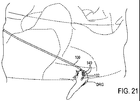
guidewire is then
removed and the sheath is used as a conduit for delivery of devices to the
epidural space.
However, the tip of the sheath tends to fold and irritate the patient during
placement through the
ligamentum flavum. Also, the conventional sheath lacks the column strength to
push through
calcified or difficult to pass tissue. Further, the introduction and removal
of each of these
-17-
CA 02749764 2011-07-14
WO 2010/083308 PCT/US2010/021041
devices increases the risk of dural puncture and patient discomfort.
Consequently, conventional
sheaths are typically abandoned in favor of directly advancing the lead into
the epidural space.
This may be possible since conventional lead placement simply involves linear
advancement
along the spinal column without significant steering, bending or curving and
conventional
sheaths provide no guiding or steering capability anyway. Conventional sheaths
are also
incapable of fitting through a conventional introducing needle due to their
size and wall
thickness. Thus, practitioners are left with manipulating the lead itself.
Sheath
[0083] The sheath 122 of the present invention comprises a hollow tube having
a stiffness
which allows advancement along the epidural space. In some embodiments, such
stiffness has a
minimum of approximately 0.65 lbs-in2 and a maximum of approximately 2.25 lbs-
in2. Thus, in
some embodiments, the sheath 122 has a stiffness of approximately 1.81 lbs-
in2.
[0084] In most embodiments, the sheath 122 has a preformed or preset bend near
its distal end
128, as illustrated in Fig. 23A, to assist in accessing the target anatomy. In
some embodiments,
the bend has an angle a of approximately 15-165 degrees, however any suitable
angle may be
used. The bend can also be characterized by the lateral distance D from the
distal tip to the outer
surface of the shaft, as illustrated in Fig. 23A. In some embodiments, the
distance D is
approximately 0.030-0.375 inches. In some embodiments, the sheath 122 is sized
and shaped for
particular types of delivery, such as antegrade, retrograde, and contralateral
approaches, to name
a few. In some embodiments, an antegrade sheath (configured for antegrade
delivery) has a bend
with an angle a of approximately 90-110 degrees and a distance D of
approximately 0.325-0.375
inches. Bends having an angle a less than or equal tol50 degrees and a
distance D of greater
than or equal to 0.225 inches typically improve the ease of delivery when
using an antegrade
approach to the DRG. In some embodiments, an alternate sheath (configured for
retrograde or
contralateral delivery) has a bend with an angle a of approximately 130-150
degrees and a
distance D of approximately 0.045-0.095 inches. Bends having an angle a less
than or equal to
165 degrees and a distance D of greater than or equal to 0.030 inches
typically improve the ease
of delivery when using a retrograde or contralateral approach to the DRG. The
sheath 122 can
be rigid enough to guide the lead 100/stylet 124 without the sheath 122
significantly deflecting.
Alternatively, the sheath 122 may be more flexible to allow increased steering
or guiding
through the anatomy.
[0085] Typically, the sheath 122 is comprised of a polymer, such as polyimide,
or
polyetheretherketone (PEEK). In preferred embodiments, the sheath 122 is
comprised of a
-18-
CA 02749764 2011-07-14
WO 2010/083308 PCT/US2010/021041
plastic material, such as a thermoset and/or thermoplastic material. Polyimide
is preferred due to
the thinness of its walls while retaining high strength, superior shape memory
and shape
retention. Polyimide can also be straightened for passage through the
introducing needle 126
without kinking. In some embodiments, the sheath 122 is comprised of polyimide
material
having a wall thickness in the range of approximately 0.002-0.006, more
particularly
approximately 0.003-0.006 inches. It may be appreciated that other materials
may be used
provided the resulting sheath has an appropriate stiffness to allow
advancement along the
epidural space, while having a wall-thickness thin enough to allow passage of
the sheath and lead
through an introducing needle to the epidural space, and while having a
sufficiently low
coefficient of friction to allow desirable passage of the lead therethrough.
Further, the resulting
sheath should be kink-resistant and formable into a desired shape. Examples of
other materials
potentially meeting these criteria include nylon, polycarbonate, acrylonitrile
butadiene styrene
(ABS), Polyethylene terephthalate (PET) and Pebax, to name a few.
[0086] Typically, the sheath 122 is comprised of a single stiffness or
unidurometer material.
This is possible because the sheath 122, lead 100 and stylet 124 are
introduced together to the
epidural space, sharing the delivery workload. In particular, since the lead
100 and stylet 124
substantially fill the inner diameter of the sheath 122, strength and kink
resistance are bolstered
for delivery robustness. In contrast, if the sheath 122 were introduced alone,
stiffness transitions,
such as durometer/materials changes, or reinforcements, such as braiding, may
be needed for
kink resistance. However, it may be appreciated that sheath 122 may optionally
be comprised of
a reinforced polymer, such as a braided polymer, or may be comprised of a
construct of various
materials. For example, the tip of the sheath 122 may be comprised of a
differing material or a
thinner material to create a less traumatic or an atraumatic tip. Such a tip
may be more flexible
than the remainder of the sheath which provides increased torqueability and
pushability. Further
it may be appreciated that the sheath 122 may optionally be comprised of a
flexible metal or
metal/polymer construct.
[0087] Delivery of the lead 100, stylet 124 and sheath 122 together also
provides a number of
other benefits. For example, preloading of the lead 100, stylet 124 and sheath
122 and
simultaneous delivery eliminates multiple steps and complications associated
with separate
introduction of each device. Further, matching the coaxial shapes of the lead
100, stylet 124 and
sheath 122 create steerability and lead control without the need for
stiffening lead construction
and without sacrificing lead flexibility and profile. In addition, preloading
of the sheath 122 with
a lead 100 having a ball shaped distal tip 106 allows the sheath 122 to have a
comparatively hard
or sharp tip because it is shielded by the atraumatic ball shape of the distal
tip 106 of the lead
-19-
CA 02749764 2011-07-14
WO 2010/083308 PCT/US2010/021041
100. Thus, the practitioner may be less concerned with traumatizing
surrounding tissue during
delivery in comparison to advancing a traditional open-tipped sheath. However,
it may be
appreciated that the distal end of the sheath 122 may optionally be formed
from a soft material,
such as Pebax, to create a more atraumatic tip for the sheath 122 itself. In
such instances, the
sheath 122 may optionally be used with a lead 100 without a ball shaped distal
tip 106 and may
be loaded on the lead 100 either from the proximal or distal ends of the lead
100.
[0088] The ball shaped distal tip 106 of the lead 100 also provides tactile
feedback when
retracted against the sheath 122. Such feedback allows the practitioner to
tactilely determine the
relative position of the lead 100 to the sheath 122. It may be appreciated
that other mechanisms
may be used to register the distal tip 106 of the lead 100 against the sheath
122, such as slots,
pins, and bands, to name a few. Alternatively, such registering may be
achieved near the
proximal end of the lead 100 and sheath 122.
[0089] In some embodiments, the sheath 122 includes a chamfer or flared edge
near its distal
end to assist in retraction of the lead 100 therein. In some instances, the
chamfer comprises
radiusing of the inside of the sheath 122 near the distal end by, for example,
approximately 0.002
inches or more. Such radiusing provides an atraumatic, smooth edge to funnel
the lead 100 and
electrodes 102 thereon into the sheath 122. Likewise, a flared edge assists in
allowing the lead
100 and electrodes 102 thereon to pass into the sheath 122 without hooking on
the distal end of
the sheath 122. This reduces any risk of damage to the lead 100, such as due
to the electrodes
102 catching on the sheath 122, and reduces procedure time since the physician
can reposition
the device without removing the entire system.
[0090] In most embodiments, the sheath 122 also includes a hub 162, such as
illustrated in Fig.
23A, near its proximal end wherein the hub 162 assists in manipulation of the
sheath 122. The
torsional rigidity of the sheath 122 allows the sheath 122 to be torqued by
rotation of the hub
162. In some embodiments, the hub 162 also provides indication of the
direction of the bend.
This assists in steering the lead 100 with or without the aid of
visualization. In instances where
visualization is used, such as fluoroscopy, an embodiment of the sheath 122
may be used which
has a radiopaque marker 164 near its distal end 128. Alternatively, the sheath
122 may be
marked with radiopaque stripes, such as along the distal end 128 or along the
length of the sheath
122. Likewise, the sheath 122 may be marked with radiopaque marker bands, such
as tungsten
or platinum marker bands, since the wall thickness of the sheath 122 is not
limited by the
epidural space.
-20-
CA 02749764 2011-07-14
WO 2010/083308 PCT/US2010/021041
[0091] Alternatively or in addition, the sheath 122 may be loaded with
radiopaque material to
provide radiopacity along the distal end 128 or along its length. In any case,
any suitable
radiopaque material may be used, such as tungsten or barium sulfate. In some
embodiments, the
sheath 122 is less radiopaque than the lead 100 so that the practitioner can
maintain visualization
of the lead 100 and can visualize the interaction of the sheath 122 and lead
100 together. Or, in
some embodiments, the sheath 122 and lead 100 each have radiopaque markers at
their
respective ends so that the practitioner is aware of their locations, both
within the anatomy and in
relation to each other. Visualization of the lead 100 and sheath 122 is
particularly useful for the
methods of the present invention which typically involve manipulation of the
devices in three
dimensions, such as movement in and out of different planes, as opposed to
conventional SCS
lead placement which occurs in two dimensions.
[0092] Such movement of the lead 100, including curving of the lead 100
through the nerve
root sleeve angulation, typically involves more and greater bends (bends
having lower radii) to
the distal end 101 of the lead 100 than conventional leads used in standard
SCS therapy.
Consequently, embodiments of the lead 100 of the present invention have a
variety of design
features to accommodate such bending and increased manipulation demands.
Typically, the lead
100 has a more flexible distal end 101 than conventional leads and has a lower
diameter. Most
embodiments of the lead 100 also minimize constraints on internal components
and utilize low
stiffness materials. Such features ease manipulation, reduce any possibility
of trauma to the
DRG and resist lead migration since less load and strain from the body will be
translated to the
distal end of the lead itself.
[0093] Referring to Fig. 23B, in some embodiments the hub 162 includes a
locking cap 165
which is used to lock the lead 100 in position within the sheath 122. Such
locking may assist in
reducing movement of the lead 100 during manipulation of the sheath 122. In
one embodiment,
the locking cap 165 has a threaded elongated portion 166 which engages with
threads within the
hub 162. The locking cap 165 also has an aperture 168 which aligns with a
lumen extending
through the sheath 122. The lead 100 is advanceable through the aperture 168
and into the
lumen of the sheath 122. When the lead 100 is desirably positioned, the lead
100 may be locked
in place by rotating the locking cap 165 which advances the threaded elongated
portion 166 into
the hub 162 and compresses a gasket 170. The gasket 170 may be comprised of
any flexible
material, such a silicone. Compression of the gasket 170 causes the gasket 170
to engage the
lead 100, thereby locking the lead 100 in place by frictional forces.
Optionally, the hub 162 may
include an injection port 172 which may be used to inject a desired medium,
such as contrast,
saline or other fluids.
-21-
CA 02749764 2011-07-14
WO 2010/083308 PCT/US2010/021041
Lead
[0094] Figs. 24A-24E illustrate an embodiment of a lead 100 of the present
invention. Fig.
24A provides a perspective view of an embodiment of a lead 100. The lead 100
comprises a
shaft 103 having a distal end 101 and a proximal end 105. In this embodiment,
the shaft 103
comprises a single lumen tube 172 formed from an extruded polymer, such as
urethane. Fig.
24B provides a cross-sectional view of the shaft 103 of Fig. 24A. Typically,
the tube 172 has an
outer diameter in the range of approximately 0.040-0.050 inches, a wall
thickness in the range of
approximately 0.005-0.010 inches and a length of approximately 12-30 inches,
however such
dimensions serve only as an example. For instance, in other embodiments, the
tube 172 has an
outer diameter in the range of approximately 0.028-0.050 inches, a wall
thickness in the range of
approximately 0.003-0.010 inches and a length of approximately 30-120cm. It
maybe
appreciated that other materials may be used, such as silicone or other
commonly used
implantable polymers.
[0095] Referring to Fig. 24B, the lead 100 also includes a stylet tube 174
disposed within the
single lumen tube 172. The stylet tube 174 forms a stylet lumen 176 and
isolates the stylet 124
from the other components of the lead 100. The stylet tube 174 also provides a
smooth or
lubricious surface against which the stylet 124 passes during insertion and
retraction. Such
lubriciousness is desirable to resist jamming or hang-ups of the highly curved
stylet 124 within
the lead 101. In addition, the lubricious surface reduces the effects on
delivery of contamination
by bodily fluids. The stylet tube 174 may also provide tensile strength to the
lead 100 during
delivery.
[0096] In some embodiments, the stylet tube 174 is comprised of polyimide.
Polyimide is a
biocompatible, high strength, smooth, flexible material. Smoothness is
provided by the means of
manufacturing, and adequate lubriciousness is provided by the low coefficient
of friction (0.7) of
the material. In some embodiments the polyimide is combined with Teflon to
lower the
coefficient of friction while maintaining high strength. Because polyimide is
high strength,
tough and smooth, stylets 124 having highly radiused bends are easier to
introduce and
manipulate therein without the stylet 124 catching, hanging, jamming or
piercing into or through
the sides of the stylet tube 174 as may occur with some polymers. In some
embodiments, the
polyimide material is loaded with a strengthening material to increase its
overall tensile strength.
Examples of such strengthening materials include engineering fibers, such as
Spectra fiber,
VectranTM fiber and Kevlar fiber, to name a few.
-22-
CA 02749764 2011-07-14
WO 2010/083308 PCT/US2010/021041
[0097] The physical qualities of the polyimide material also allows the stylet
lumen walls to be
very thin, such as approximately 0.001 inches or less, which helps to
minimizes the overall
diameter of the lead 100. Such thinness may not be achieved with the use of
some other
biocompatible polymer materials with equivalent strength and resistance to
buckling.
[0098] In other embodiments, the stylet tube 174 is comprised of
polyetheretherketone
(PEEK). PEEK is a biocompatible, high strength, and smooth material, and in a
thin-walled tube
configuration is a sufficiently flexible material. Smoothness is provided by
the means of
manufacturing, and adequate lubriciousness is provided by the fairly low
coefficient of friction
(0.35) of the material. Because PEEK is high strength, tough and smooth,
stylets 124 having
highly radiused bends are easier to introduce and manipulate therein without
the stylet 124
catching, hanging, jamming or piercing into or through the sides of the stylet
tube 174 as may
occur with some polymers.
[0099] And, in other embodiments, the stylet tube 174 is comprised of other
polymers, such as
Polyethylene Terephthalate (PET) film (also known as polyester or Mylar), or
other materials,
such as a metal tube, a flexible metal tube (such as formed from nitinol), a
laser-cut metal tube, a
spring or coil (such as a metal close-coiled spring), or a combination of
materials and forms.
[0100] As mentioned above, the stylet tube 174 may have a lubricious surface,
such as a
coating or embedded layer, along at least a portion of the stylet lumen 176 to
provide the desired
lubriciousness. An example of such a surface is a polytetrafluoroethylene
(PTFE) or parylene
coating. The tube 174 may be comprised of a material such as polyimide and
additionally
coated, or the tube 174 may be comprised of a less lubricious material and
coated to attain the
desired lubricity. Such a coating may be particularly useful when the shaft
103 is comprised of a
multi-lumen extrusion.
[0101] It maybe appreciated that alternatively, a multi-lumen tube maybe used
for the shaft
103 of the lead 100, or a combination of multi-lumen and single lumen tubing.
When such a
multi-lumen tube is formed from an extruded polymer, various other components
of the lead 100
may be coextruded with the multi-lumen tube (such as conductor cables, a
stylet tube and/or a
tensile wire described herein below). Fig. 24F illustrates an embodiment of a
shaft 103 of the
lead 100, wherein the shaft 103 comprises a 5 lumen extrusion. Four of the
lumens house
conductor cables 182; each conductor cable 182 loosely filling each lumen.
And, one larger
lumen serves as the stylet lumen 176. Typically, the stylet lumen 176 includes
a lubricious
surface 175, such as a coating or embedded layer, along at least a portion of
the stylet lumen 176
to provide the desired lubriciousness. In addition a tensile element 188 may
be co-extruded with
-23-
CA 02749764 2011-07-14
WO 2010/083308 PCT/US2010/021041
the extrusion, as shown, or the tensile element may be loosely embedded in a
sixth lumen of the
extrusion. The ability to per-insert a cable or element loosely into a small
lumen is a specialized
aspect that allows the lead 100 increased flexibility. And, although the lead
100 is typically
curved by devices such as a stylet, the distal end of the multi-lumen tube may
optionally be
thermally precurved to assist in such curvatures.
[0102] Referring back to Fig. 24A, the lead 100 also includes at least one
electrode 102. In
this embodiment, the lead 100 includes four electrodes 102 disposed along its
distal end 101.
Typically, the electrodes 102 are comprised of platinum or platinum/iridium
alloy. In this
embodiment, the electrodes 102 have a ring shape, extending around the shaft
103, and have an
outer diameter approximately equal to the outer diameter of the shaft 103. In
some
embodiments, the electrodes have a wall thickness of approximately 0.002-0.004
inches and a
length of approximately 0.030-0.060 inches or greater. It may be appreciated
that the shaped
distal tip 106 of the lead 100 may be formed from the most distal electrode.
And, it may be
appreciated a proximal end cap (described below) may serve as the most
proximal electrode.
[0103] The lead 100 also includes at least one electrical contact 180 disposed
near its proximal
end 105 which is removably connectable with a power source, such as an
implantable pulse
generator. In this embodiment, the lead 100 includes a corresponding
electrical contact 180 for
each electrode 102. Electrical energy is transmitted from the electrical
contact 180 to the
corresponding electrode 102 by a conductor cable 182 which extends
therebetween. Thus, the
cables 182 are typically approximately 18-22 inches long, but are typically up
to 120 cm (47.24
inches) long.
[0104] Referring to Fig. 24B, the conductor cables 182 extend through a space
186 between
the stylet tube 174 and the single lumen tube 172. The cables 182 may be
comprised of any
suitable material, preferably multiple Drawn Filled Tube (DFT) strands each
comprising a high
strength outer layer of cobalt-chrome alloy and a high conductivity core of
silver, platinum or
platinum/iridium alloy. Typically, the cables 182 are electrically insulated
by a thin layer of
material, such as polytetrafluoroethylene (PTFE) or perfluoroalkoxy (PFA).
Consequently, the
cables 182 typically have an outer diameter of approximately 0.006 inches.
However, it may be
appreciated that the cables 182 may be uncoated or uninsulated when the shaft
103 is comprised
of a multi-lumen extruded tube and each cable 182 extends through a dedicated
lumen, or
alternatively, when the cables are embedded in the wall of the extruded tube.
Another type of
cable construction can include a combination of high strength strands and high
conductivity
strands. Alternatively, only high strength strands, such as cobalt-chrome
alloy or stainless steel,
-24-
CA 02749764 2011-07-14
WO 2010/083308 PCT/US2010/021041
may be used. In such embodiments, resistance may be decreased by enlarging the
cable cross
section.
[0105] Each cable 182 is joined to an electrode 102 and a corresponding
electrical contact 180
by a suitable method, such as welding, brazing, soldering or crimping, to name
a few. The
joining process provides an electrical contact between the cable and the
electrode, and also
resists separation of the cable from the electrode due to any tensile forces
that the lead may be
subjected to during or after implantation. Therefore, the joining process
should be electrically
low resistance and be physically high strength. A high strength joint is
enabled by ensuring that
neither of the materials being joined are degraded by the joining process, in
addition to having
sufficient surface area, compatible materials and other factors. In preferred
embodiments, such
joining is achieved by welding which is performed using a YAG laser from the
outside of the
electrode 102, through the electrode wall. The laser joins the cable 182 with
the inner surface of
the electrode 102. In some embodiments, the weld melts the electrode alloy so
that the melt at
least partially penetrates the strands of the cable 182 which are touching the
inner surface of the
electrode 102. It is desirable that little melting of the cable 182 (e.g.
strands of DFT) occurs
because the strength properties of cobalt-chrome alloy may decrease when it is
overheated due to
welding.
[0106] In preferred embodiments, each electrode 102 is welded to the conductor
cable 182
with two welds. The two welds are approximately 0.020-0.040 inches apart along
the electrode
102. When stranded cables are used, twisting of the strands between the two
welds captures a
different set of strands in each weld. After the welding is complete, the
strands at the end of the
cable 182 are laser fused together by cutting the cable 182 to length near the
end of the electrode
102. It may be appreciated that the same methods may be used to weld the cable
182 to the
corresponding electrical contact 180.
[0107] This welding method ensures that many strands are captured by the welds
to connect
the cable 182 with the electrode 102 or electrical contact 180 without
overheating the cable
material. However, it may be appreciated that a single weld may be used. In
any case, fusing
the end of the cable 182 after welding can increase the load sharing of the
strands and the
breaking strength of the cable weld. Thus, even those strands that are not
directly welded to the
electrode 102 or electrical contact 180 can at least partially share the
tensile load through the
fusing operation.
[0108] It may be appreciated that, in some embodiments, at least some of the
cables 182 are
comprised of a single wire. In such instances, a single weld may be
sufficient. In other
-25-
CA 02749764 2011-07-14
WO 2010/083308 PCT/US2010/021041
embodiments, the cables 182 are formed together in a composite cable.
Optionally, the cables
182 may be embedded in the wall of the shaft 103.
[0109] It may also be appreciated that the electrodes 102 may have other
forms. For example,
in some embodiments, at least one electrode 102 is comprised of a plurality of
elements that are
electrically connected to each other. In other embodiments, at least one
electrode 102 extends
partially around the shaft of the lead 100 so as to impart a directional
field. In still other
embodiments, at least one electrode has a hollow cylinder shape wherein one or
more features
are cut from or through its surface. This may allow extension of the length of
the electrode
without increasing its surface area. Such longer electrodes may reduce the
effects of lead
migration. Other embodiments include diverse electrode shapes and edge
geometries in order to
affect the level and variation of current density to optimize the effect of
the energy on the target
anatomy. It may also be appreciated that at least one electrode 102 may have a
composite
structure or be comprised of pyrolite carbon which provides for surface
geometry increases.
[0110] In some embodiments, the lead 100 also includes a tensile element 188,
as illustrated in
Fig. 24B. The tensile element 188 extends through the space 186 between the
stylet tube 174
and the single lumen tube 172. In some embodiments, the tensile element 188
comprises a single
strand wire of suitable material, such as cobalt-chrome alloy. In such
embodiments, the element
188 typically has a diameter of 0.004 inches. Optionally, the element 188 may
have multiple
diameters. For instance, the element 188 may have a larger diameter near the
proximal end 105
(such as approximately 0.010 inches) and then neck down toward the distal end
101. This may
increase the ease of insertion of at least a portion of the proximal end 105
into the implantable
pulse generator yet maintain adequate flexibility in the distal end 101 of the
lead 100 while
retaining adequate tensile strength. It may be appreciated that in some
embodiments, more than
one tensile element 188 may be used. And, in some embodiments the tensile
element 188 is
comprised of other materials and forms such as metals, polymers, stainless
steel, braids, and
cables, to name a few.
[0111] The element 188 typically extends from the distal end 101 to the
proximal end 105 of
the lead 100, however the element 188 may extend any desirable distance. The
element 188 is
fastened to portions of the lead 100 that allow the element 188 to absorb
tensile stress applied to
the lead 100 during or after implantation. In particular, the element 188 is
tighter or straighter
than the conductor cables 182 so as to absorb the tensile load first. Thus,
the tensile element 188
is flexible, at least near the distal end 101, but has adequate tensile
strength (such as greater than
or equal to 2 lbf) to guard the cables 182 and welds from breakage. This is
preferable to the
conductor cables 182 and welds absorbing the tensile load and increases the
tensile strength of
-26-
CA 02749764 2011-07-14
WO 2010/083308 PCT/US2010/021041
the lead 100. Such fastening may be achieved with welding, potting, crimping,
wrapping, insert
molding or any suitable method.
[0112] In the embodiment of Fig. 24B, the stylet tube 174, the tensile element
188, and the
conductor cables 182 extend through the single lumen tube 172 and are free to
move therein.
Typically, these components are fixed to the single lumen tube 172 near its
proximal and distal
ends and the components are unattached therebetween. Thus, as the lead 100
bends or curves
during positioning, the stylet tube 174, the tensile element 188, and the
conductor cables 182 are
each able to move somewhat independently within the single lumen tube 172.
Such movement
allows greater flexibility in bending and lower applied forces to achieve
reduced curve radii in
the lead 100. It may be appreciated that the components may be fixed at other
locations,
allowing freedom of movement therebetween. Likewise, it may be appreciated
that the space
186 may optionally be filled with potting material, such as silicone or other
material.
[0113] In some embodiments, the lead 100 does not include a separate tensile
element 188. In
such embodiments, the stylet tube 174 may be reinforced with longitudinal
wires, strips, coils,
embedded braids or other elements to provide additional tensile strength.
[0114] As mentioned previously, the distal end 101 of the lead 100 has a
closed-end distal tip
106. The distal tip 106 may have a variety of shapes including a ball shape,
as shown. The
shaped tip provides an atraumatic tip for the lead 100 as well as serving
other purposes, such as
preventing the distal tip 106 from being withdrawn into the sheath 122. This
also serves as an
atraumatic tip for the sheath 122. In some embodiments, the diameter of the
shaped distal tip
106 is approximately the same as the outer diameter of the sheath 122. For
example, in the
instance of a ball shaped distal tip 106, if the diameter of the sheath 122 is
approximately 0.052-
0.057 inches, the diameter of the ball may be 0.055-0.060 inches. The ball is
also sized so as to
be passable through the introducing needle 126. However, it may be appreciated
that the distal
tip 106 may optionally be shaped to allow the lead 100 to be retracted into
the sheath 122. For
example, the lead 100 and the sheath 122 may have corresponding "keyed"
features that allow
certain rotations of the lead 100 to pass thru the sheath 122. Or, the lead
100 may include a
mechanism which causes the distal tip 106 to be reduced in diameter. Such a
mechanism may be
actuated at the proximal end of the lead, such as by the stylet 124.
[0115] Fig. 24C illustrates a cross-sectional view of an embodiment of a
distal tip 106 of a lead
100 having a ball shape, wherein the distal tip 106 is retracted against the
distal end of the sheath
122. In this embodiment, the tip 106 is molded from the same material as the
shaft 103, such as
by a catheter tipping operation. However, it may be appreciated that the ball
shape may be
-27-
CA 02749764 2011-07-14
WO 2010/083308 PCT/US2010/021041
formed from any variety of methods and materials, such as silicone, UV
adhesives,
cyanoacrylates or any suitable material that can be flowed into a shape and
cured to maintain the
shape. It may also be appreciated that the ball shaped distal tip 106 may also
have an additional
distal atraumatic feature, such as a silicone tip. Alternatively or in
addition, the distal tip 106
may be configured to allow ingrowth of tissue. For example, the distal tip 106
may be
comprised of multifilament polymers.
[0116] In this embodiment, the tip 106 also includes an internal assembly 200,
as illustrated in
Fig. 24C. Typically the internal assembly 200 is comprised of metal, such as
cobalt-chrome or
stainless steel, or other suitable material. The internal assembly 200 acts as
a hard barrier that
prevents the stylet 124 from protruding out the distal end 100 of the lead
100. In addition, the
internal assembly 200 may serve as a mechanism of attaching the stylet tube
174 to the single
lumen tube 172. Further, the internal assembly 200 may serve as an anchoring
point for the
tensile element 188. In addition, when the internal assembly 200 is comprised
of a radiopaque
material, the assembly may serve as a radiopaque marker under fluoroscopy.
[0117] It maybe appreciated that in some embodiments the distal tip 106 is not
closed-ended.
For example, the distal tip 106 may include a passageway to allow pressure
relief to aid in
inserting or withdrawing the stylet 124. Likewise, it may be appreciated that
in some
embodiments, the distal tip 106 does not include an internal assembly 200. In
such
embodiments, the stylet tube 174 maybe attached to the single lumen tube 172
by potting or
other mechanisms.
[0118] In some embodiments, the lead 100 includes potting 190 between the
stylet tube 174
and the single lumen tube 172, as illustrated in Fig. 24C. Examples of such
potting 190 include
silicone, other polymers, adhesive, or melting of the material which forms the
single lumen tube
172. Potting 190 may be disposed along the distal end 101, the proximal end
105 or along the
length of the lead 100. In some instances, the potting 190 provides additional
resistance to
failure due to such factors as electrical shorting or weld breakage. Potting
can also prevent
migration of bodily fluids through portions of the lead. Potting can also
improve ease of
insertion of the proximal end of the lead into the pulse generator.
[0119] In some embodiments, the distal end of the lead 100 is overmolded or
cast with
polymer or other suitable material to encapsulate the components, with the
exception of the outer
surface of the electrodes.
[0120] Fig. 24D provides a side cut-away view a portion of the distal end 101
of the lead 100
of Fig. 24A. An electrode 102 is shown wrapped around the single lumen tube
172, and a
-28-
CA 02749764 2011-07-14
WO 2010/083308 PCT/US2010/021041
conductor cable 182, having a stripped end, is attached to the electrode 102.
The stylet tube 174
is shown extending through the single lumen tube 172. Likewise, the tensile
element 188 is
shown extending alongside the stylet tube 174.
[0121] In some embodiments, the lead 100 includes a proximal end cap 200, such
as illustrated
in Fig. 24E. The proximal end cap 200 is disposed on the proximal end 105 of
the lead 100, as
illustrated in Fig. 24A. In this embodiment, the end cap 200 comprises a
clamping ring 202 and
a hollow shaft 204, wherein the shaft 103 of the lead 100 extends over the
hollow shaft 204 and
abuts the clamping ring 202. The shaft 103 is attached to the end cap 200 by
suitable
mechanisms, such as by adhesive, melting of the shaft material, overmolding or
by clamping
with an external ring, to name a few. The end cap 200 also includes a lumen
206 which connects
with the stylet lumen 104 of the lead 100. Thus, the stylet 124 is insertable
through the lumen
206 and advanceable therethrough. In some embodiments, the opening to the
lumen 206 is
beveled, as shown, to assist in such insertion.
[0122] The clamping ring 202 provides a solid point against which an
implantable pulse
generator connector block set screw may fixate, holding the lead 100 in place
within the header
of the pulse generator. The end cap 200 may also serve as an anchoring point
for the tensile
element 188. Likewise, the end cap 200 may be used to connect stylet tube 174
and the single
lumen tube 172 together. Typically, the end cap 200 is comprised of a metal,
such as cobalt-
chrome or stainless steel. However, the end cap 200 may alternatively be
comprised of a
polymer, optionally with an embedded strength member along the clamping ring
202 to resist the
force of the set screw. In some embodiments, the end cap 200 is used as an
electrode. In such
embodiments, the end cap 200 is connected with a conductor cable 182 and an
electrode 102
disposed on the distal end of the lead 100.
Stylet
[0123] Figs. 25, 26A-26B illustrate embodiments of a stylet 124 of the present
invention. In
some embodiments, the stylet 124 is comprised of superelastic nitinol. Nitinol
is biocompatible
and provides a variety of desirable features. For example, the nitinol
material is elastic enough
to allow the stylet 124 to straighten when inserted into a lead 100 and
captured within a straight
portion of the sheath 122. However, it is able to recover its shape once the
lead 100 is advanced
past the distal end 128 of the sheath 122, at which point the stylet 124 has
enough bending
stiffness to force the distal end 101 of the lead 100 into a desired curve for
delivery. In
particular, it forces the distal end 101 of the lead 100 to curve around
toward the target DRG
along the nerve root angulation. This allows the lead 100 to be successfully
steered to position at
-29-
CA 02749764 2011-07-14
WO 2010/083308 PCT/US2010/021041
least one of the electrodes 102 on, near or about the target DRG, particularly
by making a sharp
turn along the angle 0 of Fig. 7.
[0124] Typically, the stylet 124 has a diameter in the range of approximately
0.008-0.024
inches, preferably approximately 0.008-0.018 inches. In some embodiments, the
stylet 124 has a
diameter of 0.010 inches, particularly when used with a lead 100 having an
outer diameter of
0.040 inches. Superelastic nitinol, especially in the 0.010 inch diameter
range, has relatively low
stiffness which is beneficial for atraumatic guidance of the stylet 124/lead
100 combination near
nerve and other tissue. Thus, the stylet 124/lead 100 combination may tend to
be guided
between anatomical layers rather than be forced through tissue.
[0125] Typically, the stylet 124 has a length that is approximately 1 cm
longer than the lead
100. In addition, the distal end 130 of the stylet 124 is preset into a curve.
Fig. 25 illustrates a
stylet 124 having a primary curve X. The primary curve X may be described in
terms of an arch
shape or half circle having a perimeter along which the stylet 124 extends.
Thus, a 180 degree
primary curve X would be comprised of the distal end of the stylet 124
extending along the
entire half circle. A 90 degree primary curve X would be comprised of the
distal end of the
stylet 124 extending half way around the half circle. The primary curve X may
be formed by the
stylet 124 extending up to 360 degrees, typically up to 270 degrees, more
typically up to 180
degrees. The embodiment of Fig. 25 illustrates a primary curve X formed by the
distal end of the
stylet 124 extending 170 degrees along the perimeter of the half circle,
wherein the half circle
has a radius of 0.25 inches. In this embodiment, the distal tip of the stylet
124 has a 0.10 inch
straight section.
[0126] In some embodiments, the curve is comprised of a primary curve X and a
secondary
curve Y. The embodiment of Fig. 26A illustrates a primary curve X formed by
the distal end of
the stylet 124 extending 180 degrees along the perimeter of the half circle,
wherein the half circle
has a radius of 0.25 inches. In this embodiment, stylet 124 also has a
secondary curve Y which
is proximal and adjacent to the primary curve X. It maybe appreciated,
however, that no
secondary curve Y may be present (as in Fig. 25) or the secondary curve Y may
be formed at any
location along the stylet 124 and may not be adjacent to the primary curve X.
Typically, the
secondary curve Y has a larger radius of curvature than the primary curve X.
In this
embodiment, the secondary curve Y has a radius of curvature of 1.5 inches.
[0127] In other embodiments, the primary curve X and/or secondary curve Y are
compound
curves. A compound curve is comprised of two or more subcurves. For example,
Fig. 26B
illustrates primary curve X comprised of a subcurve having a radius of
curvature of 0.25 inches
-30-
CA 02749764 2011-07-14
WO 2010/083308 PCT/US2010/021041
and another subcurve having a radius of curvature of 0.37 inches. Such
compound curvatures
allow for greater variety of overall shape. In this example, the compound
curvature creates a
slightly wider primary curve X.
[0128] Overall, the primary curve X may be considered "U" shaped. It may be
appreciated,
that other curve shapes may be used to increase ease of delivery or increase
anchoring of the lead
100 about the desired anatomy. Examples include a "V" shape, an "S" shape or a
coil, to name a
few.
[0129] It may be appreciated that the stylet 124 is formed from other
materials in other
embodiments, such as metals, alloys, polymers and stainless steel. Stainless
steel may be
preferred with the lead 100 is to be delivered in a relatively straight or
straighter configuration.
The stylet 124 may be supplied in a straight or pre-bent configuration.
Likewise, the stylet 124
may be bent by the practitioner prior to insertion into the lead 100.
[0130] In some embodiments, the distal tip of the stylet 124 is rounded or
otherwise formed to
resist embedding into the wall of the stylet tube 174 or damaging the stylet
tube 174 during
insertion. Likewise, in some embodiments, the stylet 124 is coated with
polytetrafluoroethylene
(PTFE), parylene or other coating material to increase lubricity. This eases
insertion of the stylet
124 through the stylet tube 174 and resists jamming or hangups. In addition, a
lubricious coating
can increase tactile feedback of the stylet motion within the lead 100. As
mentioned above, such
lubricity may be provided by the stylet tube 174 itself or a coating along the
stylet lumen 176,
however such coating of the stylet 124 may be used alternatively or in
addition.
[0131] In some embodiments, the stylet 124 includes a gripping device near its
proximal end.
The gripping device allows the stylet 124 to be more easily or more
ergonomically grasped for
torquing the stylet 124. Such torquing changes the steering direction of the
distal end 130 of the
stylet 124. The gripping device may be fixedly or removably attached to the
stylet 124. In some
embodiments, the gripping device also indicates the direction of the curvature
of the distal end
130.
[0132] It maybe appreciated that more than one stylet 124 maybe inserted into
a lead 100,
particularly into the same stylet tube 174. In such instances, each stylet 124
may have a different
bend geometry or stiffness and manipulation of the stylets 124 could allow for
increased steering
capability. Likewise, the lead 100 may include more than one stylet tube 174
or insertion of
multiple stylets 174.
[0133] Alternatively or in addition, the shape and stiffness of the stylet 124
may be actively
controlled with the use of control wires or other similar devices. For
instance, in some
-31-
CA 02749764 2011-07-14
WO 2010/083308 PCT/US2010/021041
embodiments, the stylet 124 has a tubular shape and features are cut partially
through the tube
diameter near the distal end of the stylet 124. This allows the tube to
elastically bend in the
region of the cut features. A thin wire is attached to an inner wall of the
tubular stylet 124
distally of the cut features and extends through the proximal end of the tube
to an actuating
handle. When the wire is put under tension, the distal end of the stylet 124
bends from its
original shape. When the tension is removed, the distal end of the stylet 124
recovers to its
original shape. More than one wire can be used for multiple bends. Such a
stylet 124 may be
comprised of any suitable materials, particularly superelastic nitinol.
[0134] It may be appreciated that in some embodiments, the stylet 124 is
fixedly attached or
embedded in the lead 100. In such instances, the stylet 124 serves to maintain
curvature,
steerability and stiffness to the lead 100 and is not removed.
[0135] It may further be appreciated that the lead 100, stylet 124 or sheath
122 may
alternatively be manipulated by active steering control elements. Such control
elements would
be managed by external controls.
[0136] It may further be appreciated that the stylet 124 and/or sheath 122 may
have a
substantially straight configuration. Such a straight configuration may be
particularly useful
when making larger bends, such as 90 degree bends. For example, if the nerve
root angulation of
the target DRG is relatively large, a straight sheath 122 may be used to
position the lead 100 near
the nerve root wherein the curved stylet 124 allows the lead 100 to bend along
the nerve root
angulation upon exiting the sheath 122. Thus, together the sheath 122 and
stylet 124 form an
approximately 90 degree bend. Or, the curvature of the sheath 122 itself may
be sufficient to
direct the lead 100 toward the target DRG. In such instances, a straight
stylet 124 may be used
or the lead 100 may be advanced without the use of a stylet.
Shapeable Sheath Embodiments
[0137] In some embodiments, the sheath 122 is comprised of a shapeable
material. Such a
material is shapeable by simply bending the material, wherein the material
substantially
maintains the bent shape. In preferred embodiments, the shapeable material
comprises
polyimide with stainless steel wires embedded therein. The wires assist in
providing strength
and shapeability. In some embodiments, the wires are embedded axially therein.
Any number of
wires may be present, such as one, two, three, four, six, eight or more. In
some embodiments,
four wires are present. The wires may have a variety of thicknesses. Example
materials include
470-VII.5 PTFE ID/BRAID w/4 AXIAL supplied by MicroLumen (Tampa, FL). In other
embodiments, one or more wires are embedded in a coiled configuration.
-32-
CA 02749764 2011-07-14
WO 2010/083308 PCT/US2010/021041
[0138] Typically, sheaths 122 comprised of a shapeable material have the same
features as the
sheaths 122 described above and are used with the other delivery devices in
the same manner.
However, the shapeable sheath does not rely on a preformed or preset bend near
its distal end.
Rather, the shapeable sheath can be bent to any angle a at the time of use.
Likewise, the
shapeable sheath can be rebent and readjusted as many times as desired. This
allows the
practitioner to adjust the angle a as needed before or during a procedure to
more desirably access
the target anatomy. This may be particularly useful in patients that have
irregular anatomy or
unanticipated anatomical features, such as due to progressive disease.
Multiple Sheath Embodiments
[0139] It may also be appreciated that multiple sheaths may be used to
desirably direct the lead
100 toward a target anatomy, such as a target DRG. For example, as illustrated
in Fig. 27, an
additional sheath 122' may be used with the above described delivery system
120. In such
situations, the additional sheath 122' is advanceable through sheath 122, and
the lead 100 is
advanceable through the additional sheath 122'. The additional sheath 122' may
have any
desired curvature or may be substantially straight. Each of the sheath 122,
the additional sheath
122' and the lead 100 may be advanced and retracted in relation to each other.
In some
embodiments, the sheaths are moveable so that its distal end of the additional
sheath 122'
extends approximately 12-20mm, typically approximately 15mm, beyond the distal
end of the
sheath 122. Such movements, in combination with the shapes (e.g. curvatures)
of the delivery
devices, provide increased maneuverability and variety in the angles through
which the devices
may be advanced. In addition, the multiple sheath design increases the ability
to impart lateral
forces, such as toward a foramen, particularly at substantial distances from
the entry point to the
epidural space. As described above, the delivery system 120 may be used to
target anatomy at
multiple spinal levels above or below the insertion point of the needle. The
greater the distance
from the insertion point, the ability to impart lateral forces with the sheath
122 becomes more
challenging. In some instances, a foramen may be at least partially stenosed,
creating difficulty
in advancing a lead therein. It maybe desired to impart lateral forces with
the sheathl22 to
access this type of foramen. The additional sheath 122' provides additional
stiffness,
steerability, and length which can be helpful in such access.
[0140] In some embodiments, the additional sheath 122' has a substantially
straight
configuration. A straight configuration may be used to traverse greater
expanses than with the
sheath 122 alone. For example, in some patients and/or in some portions of the
anatomy (such as
in the sacrum or when advancing through the sacral hiatus) the epidural space
may be
particularly wide. Or, the sheath 122 may be positioned within the epidural
space between the
-33-
CA 02749764 2011-07-14
WO 2010/083308 PCT/US2010/021041
midline and the "gutter" of the epidural space opposite the target DRG, as
illustrated in Fig. 28,
so that a larger portion of the epidural space is to be traversed. Traversing
these greater expanses
may be more easily achieved with the use of an additional sheath 122'. In such
embodiments, the
additional sheath 122' has a stiffness that allows for transverse translation.
Advancement or
translation of the sheath 122' may be achieved with the use of, for example, a
sliding mechanism
disposed within the hub 162. The lead 100 is then advanceable through the
additional sheath
122', such as described above, to a position so as to stimulate the target
DRG.
[0141] In one embodiment, the sheath 122 has an outer diameter of
approximately 0.063
inches, an inner diameter of approximately 0.057 inches, and a working length
of approximately
30 cm. In this embodiment, the additional sheath 122' has an outer diameter of
approximately
0.052 inches, an inner diameter of approximately 0.046 inches and a working
length of
approximately 45cm. Together, the sheaths 122, 122' are passable through a 14
gauge needle
having an inner diameter of approximately 0.067 inches.
[0142] In some embodiments, the sheath 122 has a curvature and the additional
sheath 122'
also has a curvature. In such instances, retraction of the additional sheath
122' within the sheath
122 may cause the two curvatures to wedge together. This may be prevented by
restricting the
distance the additional sheath 122 may be retracted within the sheath 122. In
some
embodiments, this is achieved by a control hub 162 having a sliding mechanism
and a limiter.
Figs. 29A, 29B, 29C illustrate a perspective view, a side view and a front
view, respectively, of
an embodiment of such a control hub 162. Here, the hub 162 includes a base 300
and a slidable
extender 302. The base 300 attaches to the proximal end of the sheath 122 and
the slidable
extender 302 attaches to the proximal end of the additional sheath 122'.
Advancement and
retraction of the extender 302 in relation to the base 300, moves the
additional sheath 122' in
relation to the sheath 122. Such advancement and retraction is limited by a
limiter. In this
embodiment, the limiter comprises a protrusion 306 along the extender 302
which protrudes into
a slot 308 along the base 300. The protrusion 306 slides along the slot 308 as
the extender 302
moves, limited at each end by the confines of the slot 308. Thus, in this
embodiment,
advancement is limited in addition to retraction. Such limitation of
advancement may be used
when a predetermined or known distance of advancement is desired. In some
embodiments, the
predetermined distance is 15mm. Likewise, when repeated advancement and
retraction is
desired, such as to penetrated through an obstruction, the use of the limiter
304 may be desired.
This allows quick, repeatable movements through a known distance without risk
of over-
advancement or over-retraction. In some embodiments, the hub 162 includes
ergonomic handles
to assist in manipulation. For example, in one embodiment, the extender 302
includes a ring 310
-34-
CA 02749764 2011-07-14
WO 2010/083308 PCT/US2010/021041
and the base 300 includes hooks 312. Insertion of fingers under the hooks 312
and a thumb
through the ring 310 allows easy one-handed manipulation of the hub 162 by
moving the thumb
toward and away from the fingers of the hand.
Other Embodiments
[0143] It maybe appreciated that the devices of the present invention maybe
used in any
combination or subcombination. For example, one or more leads 100 may be
delivered with the
use of one or more sheaths 122, without the use of a stylet 124. In some
instances, the lead 100
is floppy, having no preset curvature, and is simply directed by the sheath(s)
to the target
anatomy. The lead 100 is then advanced, or the sheath(s) are retracted, so
that the lead is
desirably positioned. In other instances, the lead 100 has a preset curvature
which assists in
directing the lead 100 to the target anatomy upon advancement.
[0144] Likewise, the lead 100 maybe delivered with the use of a stylet 124,
without the use of
one or more sheaths. In such instances, the lead 100 may be steered by
manipulation of the stylet
124, such as by advancing, retracting and torquing the stylet 124. The lead
100 and/or the stylet
124 may have a curvature.
[0145] It maybe appreciated that the devices of the present invention maybe
substantially
straight or may have one or more curves. As mentioned above, the devices may
be used in any
combination or sub combination, including any combination of straightness or
curvatures. For
example, a curved sheath may be used with a straight stylet or a straight
sheath may be used with
a curved stylet. Any of these can be used with a lead having no curvature or
with a lead having a
preset curvature. Similarly, a substantially straight first sheath may be used
with a curved
second sheath or vice versa. Or both sheaths may be curved. Likewise, any
number of sheaths
may be used with any combination of curvatures. Likewise, each combination can
be used with
curved or straight stylets or curved or straight leads. Thus, all combinations
and
subcombinations are conceived.
[0146] The desired combination of devices and curvatures may depend on a
variety of factors,
including the approach used (such as antegrade, retrograde or contralateral),
the choice of target
anatomy, and the particular anatomical features of the individual patient, to
name a few.
[0147] It may further be appreciated that when a delivery device is described
as directing the
lead toward a target anatomy, such direction may be in the general vicinity of
the target anatomy
allowing for additional steps to direct the lead even closer toward the target
anatomy. For
example, a curved sheath may direct the lead away from the midline of the
spinal column,
toward a target DRG. However, straight advancement of the lead therefrom may
be below,
-35-
CA 02749764 2011-07-14
WO 2010/083308 PCT/US2010/021041
above or not desirably close enough to the target DRG. Therefore, additional
directing of the
lead toward the target DRG may be desired to position the lead closer to the
target DRG. For
example, a curved stylet may be used to direct the lead again toward the
target DRG, such as
along a nerve root sleeve angulation. Such steps may optimize positioning of
the lead.
Connection to Implantable Pulse Generator
[01481 As mentioned above, the proximal ends of the leads 100 are connected
with an IPG
which is typically implanted nearby, such as along the back, buttock or
abdomen. The IPG may
be any conventional IPG which provides stimulation signals to the one or more
leads. Or, the
IPG may be particularly adapted for targeted treatment of the desired
anatomies. For example,
the delivery devices of the present invention may be used in combination with
the implantable
stimulation system described in U.S. Patent Application No. 12/607,009,
"Selective Stimulation
Systems and Signal Parameters for Medical Conditions" filed October 27, 2009,
incorporated
herein by reference for all purposes. Such targeted treatment minimizes
deleterious side effects,
such as undesired motor responses or undesired stimulation of unaffected body
regions. This is
achieved by directly neuromodulating a target anatomy associated with the
condition while
minimizing or excluding undesired neuromodulation of other anatomies. In some
embodiments,
the lead and electrode(s) are sized and configured so that the electrode(s)
are able to minimize or
exclude undesired stimulation of other anatomies. In other embodiments, the
stimulation signal
or other aspects are configured so as to minimize or exclude undesired
stimulation of other
anatomies.
Strain Relief Support for Lead Connection to IPG
[0149] Typically, the IPG is surgically implanted under the skin at a location
that is remote
from the stimulation site. The leads are tunneled through the body and
connected with the IPG
to provide the stimulation pulses. Fig. 30 illustrates a conventional
stimulation system 510 used
to stimulate tissues or organs within the body. The system 510 includes an IPG
512 and at least
one lead 514. The IPG 512 includes a header 516 having at least one connection
port 518 for
electrically connecting with the lead 514. The lead 514 includes at least one
electrode 520,
typically disposed near its distal end 522, and a conductive wire extending
from each electrode
520 to its proximal end 524. The proximal end 524 of the lead 514 is inserted
into the
connection port 518 to electrically connect the conductive wire with the
electronic circuitry
within the IPG 512.
[0150] The leads are generally of a fragile nature and care must be taken to
minimize strain on
the leads during implantation and throughout the life of the device. To reduce
strain on the lead,
-36-
CA 02749764 2011-07-14
WO 2010/083308 PCT/US2010/021041
the lead is often implanted in a looped configuration and sutured in place. In
this manner, strain
put on the lead may be absorbed by the looped coil. However, this practice
involves additional
manipulation of the fragile lead and a larger implantation area to accommodate
the looped
configuration.
[0151] In addition, a particularly vulnerable portion of the lead is the point
of connection with
the IPG. It is typically desired that the lead be soft and "floppy" so as to
conform to bends in the
anatomy along its path. In contrast, the IPG is typically a rigid body
configured to withstand
encapsulation and tissue contraction. To connect the lead to the IPG a portion
of the lead is
inserted into the IPG and fixed in place. Thus, as the lead exits the IPG the
lead endures an
abrupt transition from fully supported by the IPG to fully unsupported. This
portion of the lead
is vulnerable to kinking, strain and damage. In addition, the soft and floppy
characteristics of the
lead may also prove challenging when trying to insert the lead into the IPG.
[0152] Thus, it is desired to provide devices, systems and methods for
improving handling of
the lead, including insertion of the lead into an IPG, and reducing any
vulnerability of the lead in
the area of connection to the IPG. At least some of these objectives will be
met by the present
invention.
[0153] Devices, systems and methods are provided to improve connectability of
a lead, such as
a conventional lead or any of the leads of the present invention described
herein, to an IPG and
to reduce any vulnerabilities of this connection. As mentioned above, the soft
and floppy
characteristics of many leads may provide both handling issues and longevity
issues when
connected with an IPG. For example, insertion of a floppy lead into an IPG may
be difficult and
time consuming. And, the portion of the lead exiting the IPG may be vulnerable
to kinking,
strain and damage. The present invention assists in overcoming these issues by
providing a
strain relief support which is joinable with the proximal end of a lead. The
support provides
rigidity to the proximal end of the lead to assist in handling and insertion
of the proximal end of
the lead into an IPG. And the support protects the lead from possible
vulnerabilities near the
connection point with the IPG.
[0154] Fig. 31 illustrates an embodiment of a strain relief support 530 of the
present invention.
The support 530 comprises a support member 532 and a detachable hub 534. In
this
embodiment, the support member 532 comprises an elongate shaft sized to be
inserted into the
proximal end 524 of a lead 514. Typically, the lead includes a plurality of
lumens, such as a
separate lumen for each conductive wire. Additionally, the lead may include a
stylet lumen or
other lumen. The support member 532 is typically inserted into the stylet
lumen or other lumen
-37-
CA 02749764 2011-07-14
WO 2010/083308 PCT/US2010/021041
so as to internally support the proximal end of the lead. However, it may be
appreciated that the
support member 532 may be inserted into any lumen or be attached to an outer
surface of the
lead. The hub 534 is attachable to the support member 532 to provide a handle
or gripping
structure to assist in manipulating the support member 532.
[0155] The strain relief support 530 maybe comprised of any suitable materials
including
metals (such as stainless steel, nitinol, MP35N, etc.) or plastics (such as
nylon, polycarbonate,
polyurethane, etc.).
[0156] Fig. 32 illustrates a cross-section of the strain relief support 530,
including the support
member 532 and the hub 534. As shown, the support member 532 has an end
structure 536
which is disposed within the hub 534. The hub 534 includes a plunger 538
comprising a plunger
button 540 attached to a plunger shaft 542. The plunger shaft 542 extends
through a channel 544
in the hub 534 toward the end structure 536 of the support member 532.
Depression of the
plunger button 540 translates the plunger shaft 542 through the channel 544 so
that the plunger
shaft 542 contacts the end structure 536. Continued depression applies force
to the end structure
536 and pushes the end structure 536 out of the hub 534 as the hub material
flexes to allow such
movement. The support member 532 is thus released and the hub 34 is considered
detached. It
may be appreciated that the hub 534 may alternatively be detached by other
mechanisms, such as
by break-away from a friction fit with the support member 532.
[0157] Figs. 33-35 illustrate insertion of the support member 32 into the
proximal end 524 of a
lead 514. Once the proximal end 524 of the lead 514 has been tunneled to a
pocket location
within the patient's body and the pocket is ready to accept the IPG, the
proximal end 524 is
ready to receive the support member 532. Typically, the support member 532 is
pre-attached to
the hub 534 to allow easy grasping by the user. The user holds the hub 534 and
directs the
support member 532 into the proximal end 524 of the lead 514, as shown in Fig.
33. In
particular, the support member 532 is inserted into a desired lumen in the
lead 514. The hub 534
is then detached from the support member 532 by depression of the plunger
button 540, as
illustrated in Fig. 34. Fig. 35 provides a side view of Fig. 34. As shown, the
plunger shaft 542
has pushed the end structure 536 out of the hub 534 so that the hub 534 is
detached and can be
disposed or recycled. The support member 532 can be further inserted into the
lead 514 so that
the end structure 536 abuts the lead 514, as shown in Fig. 36. Such insertion
can be achieved by
pushing the end structure 536, such as with a finger or tool, until the end
structure 536 is
desirably positioned. Typically, the end structure 536 is sized to be larger
than the lumen into
which the support member 532 is being inserted so as to remain outside of the
lead 514. This
resists distal migration of the support member 532 and allows for easy removal
of the support
-38-
CA 02749764 2011-07-14
WO 2010/083308 PCT/US2010/021041
member 532 from the proximal end 524 if desired. In this embodiment, the end
structure 536
has a round or ball shape, however it may be appreciated that the structure
536 may have any
suitable shape, particularly a shape which is easily graspable and resists
insertion into the lead
514. However, it may be appreciated that the end structure 536 may optionally
be sized and
shaped to be inserted into the proximal end 524 of the lead 514 if desired.
[0158] The proximal end 524 of the lead 514 may then be inserted into the
connection port 518
of the IPG 512, as illustrated in Fig. 37. The support member 532 provides
rigidity to the
proximal end 524 of the lead 514 to assist in handling during insertion of the
proximal end 524
into the connection port 518. The proximal end 524 may then be fixed within
the connection
port 518 with the use of a set screw 550. The set screw 550 is advanced toward
the lead 514 and
tightened against the lead 514 to hold the lead 514 within the connection port
518 by frictional
force. In some embodiments, the lead 514 includes a cuff 552 aligned to
contact the set screw
550. The cuff may be comprised of any suitable material, such as MP35N (CoCr).
Such fixation
of the support member 532 within the connection port 518 also resists
dislodgement of the
support member 532 and possible migration.
[0159] As shown, the support member 532 extends beyond the IPG 512 so that the
lead 514 is
supported outside of the IPG 512. This diminishes the abrupt transition from
fully supported by
the IPG 512 to fully unsupported. Consequently, this portion of the lead is
less vulnerable to
kinking, strain and damage. It may be appreciated that the support member 532
may be tapered
toward its distal end to gradually reduce stiffness along the lead 514 as the
lead 514 exits the
connection port 518.
[0160] The above described embodiment shows the support member 532 having a
straight
shape. It may be appreciated that the support member 532 may alternatively
have a curved, bent,
folded, compound shape or other shape.
Applications
[0161] It may be appreciated that the devices, systems and methods of the
present invention
may be used or adapted for use in stimulating other neural targets or other
tissues throughout the
body. Some examples include occipital nerves, peripheral nerve branches,
nerves in the high
cervical area, nerves in the thoracic area, and nerves in the lower sacral
area.
[0162] A variety of pain-related conditions are treatable with the systems,
methods and devices
of the present invention. In particular, the following conditions may be
treated:
1) Failed Back Surgery syndrome
-39-
CA 02749764 2011-07-14
WO 2010/083308 PCT/US2010/021041
2) Chronic Intractable Low Back Pain due to:
A) Unknown Etiology
B) Lumbar facet disease as evidenced by diagnostic block(s)
C) Sacroiliac Joint disease as evidenced by diagnostic block(s)
D) Spinal Stenosis
E) Nerve root impingement - non-surgical candidates
F) Discogenic Pain - discography based or not
3) Complex Regional Pain Syndrome
4) Post-Herpetic Neuralgia
5) Diabetic Neuropathic Pain
6) Intractable Painful Peripheral Vascular Disease
7) Raynaud's Phenomenon
8) Phantom Limb Pain
9) Generalized Deafferentation Pain Conditions
10) Chronic, Intractable Angina
11) Cervicogenic Headache
12) Various Visceral Pains (pancreatitis, etc.)
13) Post-Mastectomy Pain
14) Vulvodynia
15) Orchodynia
16) Painful Autoimmune Disorders
17) Post-Stroke Pain with limited painful distribution
18) Repeated, localized sickle cell crisis
19) Lumbar Radiculopathy
20) Thoracic Radiculopathy
-40-
CA 02749764 2011-07-14
WO 2010/083308 PCT/US2010/021041
21) Cervical Radiculopathy
22) Cervical axial neck pain, "whiplash"
23) Multiple Sclerosis with limited pain distribution
Each of the above listed conditions is typically associated with one or more
DRGs wherein
stimulation of the associated DRGs provides treatment or management of the
condition.
[0163] Likewise, the following non-painful indications or conditions are also
treatable with the
systems, methods and devices of the present invention:
1) Parkinson's Disease
2) Multiple Sclerosis
3) Demylenating Movement Disorders
4) Physical and Occupational Therapy Assisted Neurostimulation
5) Spinal Cord Injury - Neuroregeneration Assisted Therapy
6) Asthma
7) Chronic Heart Failure
8) Obesity
9) Stroke - such as Acute Ischemia
Again, each of the above listed conditions is typically associated with one or
more DRGs
wherein stimulation of the associated DRGs provides treatment or therapy. In
some instances,
Neuroregeneration Assisted Therapy for spinal cord injury also involves
stimulation of the spinal
column.
[0164] It maybe appreciated that the systems, devices and methods of the
present invention
may alternatively or additionally be used to stimulate ganglia or nerve
tissue. In such instances,
the condition to be treated is associated with the ganglia or nerve tissue so
that such stimulation
provides effective therapy. The following is a list of conditions or
indications with its associated
ganglia or nerve tissue:
1) Trigeminal Neuralgia (Trigeminal Ganglion)
2) Hypertension (Carotid Sinus Nerve / Glossopharangyl Nerve)
3) Facial Pain (Gasserian Ganglion)
-41-
CA 02749764 2011-07-14
WO 2010/083308 PCT/US2010/021041
4) Arm Pain (Stellate Ganglion)
5) Sympathetic Associated Functions (Sympathetic Chain Ganglion)
6) Headache (Pterygoplatine Ganglion/Sphenopalatine Ganglion)
[0165] It may also be appreciated that the systems and devices of the present
invention may
also be used to stimulate various other nerve tissue including nerve tissue of
the peripheral
nervous system, somatic nervous system, autonomic nervous system, sympathetic
nervous
system, and parasympathetic nervous system, to name a few. Various features of
the present
invention maybe particularly suited for stimulation of portions of these
nervous systems. It may
further be appreciated that the systems and devices of the present invention
may be used to
stimulate other tissues, such as organs, skin, muscle, etc.
[0166] Although the foregoing invention has been described in some detail by
way of
illustration and example, for purposes of clarity of understanding, it will be
obvious that various
alternatives, modifications, and equivalents may be used and the above
description should not be
taken as limiting in scope of the invention which is defined by the appended
claims.
-42-