Sélection de la langue

Search

Sommaire du brevet 2750567 

Énoncé de désistement de responsabilité concernant l'information provenant de tiers

Une partie des informations de ce site Web a été fournie par des sources externes. Le gouvernement du Canada n'assume aucune responsabilité concernant la précision, l'actualité ou la fiabilité des informations fournies par les sources externes. Les utilisateurs qui désirent employer cette information devraient consulter directement la source des informations. Le contenu fourni par les sources externes n'est pas assujetti aux exigences sur les langues officielles, la protection des renseignements personnels et l'accessibilité.

Disponibilité de l'Abrégé et des Revendications

L'apparition de différences dans le texte et l'image des Revendications et de l'Abrégé dépend du moment auquel le document est publié. Les textes des Revendications et de l'Abrégé sont affichés :

  • lorsque la demande peut être examinée par le public;
  • lorsque le brevet est émis (délivrance).
(12) Brevet: (11) CA 2750567
(54) Titre français: STRUCTURE POUR ASSUJETTIR UN OUTIL A UN TUBE DE CADRE
(54) Titre anglais: STRUCTURE FOR ATTACHING A TOOL TO A FRAME TUBE
Statut: Périmé et au-delà du délai pour l’annulation
Données bibliographiques
(51) Classification internationale des brevets (CIB):
  • A01B 23/00 (2006.01)
  • A01B 23/02 (2006.01)
(72) Inventeurs :
  • BEECK, MARK D. (Etats-Unis d'Amérique)
  • CONNELL, RICHARD J. (Etats-Unis d'Amérique)
  • HACKERT, RYAN A. (Etats-Unis d'Amérique)
(73) Titulaires :
  • DEERE & COMPANY
(71) Demandeurs :
  • DEERE & COMPANY (Etats-Unis d'Amérique)
(74) Agent: BORDEN LADNER GERVAIS LLP
(74) Co-agent:
(45) Délivré: 2018-01-23
(22) Date de dépôt: 2011-08-26
(41) Mise à la disponibilité du public: 2012-03-09
Requête d'examen: 2016-07-26
Licence disponible: S.O.
Cédé au domaine public: S.O.
(25) Langue des documents déposés: Anglais

Traité de coopération en matière de brevets (PCT): Non

(30) Données de priorité de la demande:
Numéro de la demande Pays / territoire Date
12/878,617 (Etats-Unis d'Amérique) 2010-09-09

Abrégés

Abrégé français

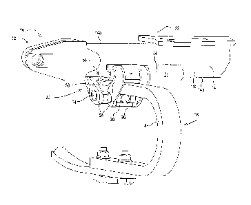
Une structure de rail à tube multiple est fixée aux angles inférieurs avant et arrière du tube multiple pour fournir un support de serrage inférieur. Deux mâchoires de serrage pivotantes reliées au support de serrage sont fixées contre ce dernier en serrant un boulon de serrage unique sétendant entre les parties les plus basses des mâchoires. Un patin de positionnement est fixé entre le tube et le ressort en C et comporte une partie saillante qui fait saillie dans un orifice dans le ressort en C. Les extrémités du patin de positionnement comprennent de petites pattes qui senroulent autour du rail à tube multiple. Le boulon de serrage unique fournit une force de serrage verticale qui correspond à environ deux fois la tension générée dans le boulon lorsque lécrou est serré.


Abrégé anglais


Gang tube rail structure is attached to the lower front and rear corners of
the
implement gang tube to provide a lower clamp support. Two pivoting clamp jaws
are
attached to the clamp support and secured against the support by tightening a
single
clamp bolt extending between the lowermost portions of the jaws. A locator
shoe is
secured between the tube and the c-spring and includes a protrusion that
projects
into a hole in the c-spring. The ends of the locator shoe include short legs
that wrap
around the gang tube rail. The single clamp bolt provides a vertical clamp
force that
is approximately twice the tension generated in the bolt when the nut is
tightened.

Revendications

Note : Les revendications sont présentées dans la langue officielle dans laquelle elles ont été soumises.


CLAIMS:
1. A tool mount for connecting a tool shank to a horizontal frame member of
an
implement, the tool mount comprising:
first and second spaced rail members disposed horizontally and respectively
being connected to opposite sides of a lowermost portion of the frame member;
a tool support including opposed first and second clamp members having
upper ends defining jaws respectively engaging the first and second spaced
rail
members and being joined to lower ends spaced below the frame member, with
each clamp member defining a tool shank-receiving opening below, and extending
crosswise to, the frame member;
a jaw tightening member extending between the opposed clamp members
below the spaced rail members and the tool shank-receiving opening of each
clamp
member to urge lower portions of the clamp members towards each other to clamp
the tool support to the rail members at the lowermost portion of the frame
member
independently of additional fasteners above the rail members.
2. A tool mount for connecting a tool shank to a horizontal frame member of
an
implement, the tool mount comprising:
first and second first and second spaced rail members disposed horizontally
and respectively being connected to opposite sides of a lowermost portion of
the
frame member;
a tool support including opposed first and second clamp members having
upper ends defining jaws respectively engaging the first and second spaced
rail
members, with the clamp members depending from the rail members and defining a
tool shank-receiving portion below the frame member;
a jaw tightening member extending between the opposed clamp members
below the spaced rail members and the tool shank-receiving portion to urge
lower
portions of the clamp members towards each other to clamp the tool shank to
the

rail members at the lowermost portion of the frame member independently of
additional fasteners above the rail members; and
a positioning member located in the tool shank-receiving portion mating with
the clamp members and the tool shank and preventing relative movement of the
tool shank and the rail members.
3. The tool mount as set forth in claim 2 wherein the positioning member
includes legs embracing the rail members.
4. The tool mount as set forth in claim 1 wherein the jaw tightening member
includes a bolt-receiving member pivotally mounted to a lower portion of each
clamp
member, thereby defining a trunnion, and a bolt extending between the clamp
members and through the bolt-receiving member of each clamp member and
having nut on one end that is tightenable for drawing the lower portions of
the clamp
members together.
5. The tool mount as set forth in claim 1 wherein the frame member is
substantially rectangular in cross section thereby defining first and second
lower
corners; the first and second rails comprise respective metal plates formed so
as to
have a J-shaped cross section and being respectively fixed to said frame
member
so as to extend along said first and second lower corners of the frame member.
6. The tool mount as set forth in claim 1 wherein the rails and jaws are
shaped
to permit the jaws to pivot on the rails and wherein the jaw tightening member
includes a bolt extending between the clamp members and tightenable to draw
the
lower portions together and upwardly towards the frame member.
7. A tool mount for connecting a tool shank to a horizontal, transverse
frame
member of an implement, the frame member having upper and lower faces joined
by front and rear sides, the tool mount comprising:
6

spaced horizontal, parallel front and rear rails respectively being connected
to lowermost portions of the front and rear sides of the frame member;
a clamping structure including opposed first and second clamp members
having upper ends defining first and second jaws respectively engaging the
spaced
rail members, the clamp members depending from the rail members and defining a
tool shank-receiving portion below the frame member with respective engaged
surfaces of the rails and jaws being shaped such that the tool shank receiving
portions of the clamp members move upwardly as lower ends of the clamp
members are moved toward each other;
a jaw tightening member extending between the opposed clamp members
below the tool shank-receiving portion, and hence below the lower face of the
frame
member, and acting to urge the clamp jaws towards each other and urge the
shank-
receiving portion upwardly towards the lower face of the frame member so as to
impart a clamping force on a tool shank received in the shank-receiving
portion, the
clamp members and rails thus being located substantially below the upper face
of
the frame.
8. The tool mount as set forth in claim 7 wherein the first and second
rails are
respectively connected to lowermost corners of the frame member defined by the
lowermost face and the front and rear sides.
9. The tool mount as set forth in claim 7 wherein the clamp members are
each
j-shaped in side view, with the rail members having mating cross sections
which
respectively mate with the engaged surfaces of the jaws.
10. The tool mount as set forth in claim 9 wherein the jaw-tightening
member
comprises a bolt member extending between lower ends of the clamp members.
7

11. A tool mount for connecting a tool shank to a horizontal, transverse
frame
member of an implement, the frame member having upper and lower faces joined
by front and rear sides, the tool mount comprising:
rail members connected to a lowermost portion of the front and rear sides of
the frame member;
a clamping structure including opposed first and second clamp members
having upper ends defining first and second jaws respectively engaging the
spaced
rail members, the clamp members depending from the rail members and defining a
tool shank-receiving portion below the frame member;
a jaw tightening member extending between the opposed clamp members
below the tool shank-receiving portion, and hence below the lower face of the
frame
member, and acting to urge the clamp jaws towards each other and to impart an
upward clamping force on a tool shank received in the shank-receiving portion,
with
the clamp members jaws and rails thus being located substantially below the
upper
face of the frame; and
a tool mounting insert being connected between the clamp members for
engaging the tool shank and the rails.
12. The tool mount as set forth in claim 11 wherein the insert includes an
indexing portion for mating with the tool shank.
13. The tool mount as set forth in claim 11 wherein the insert includes
downturned sides embracing opposite sides of the tool shank.
14. The tool mount as set forth in claim 11 wherein the insert includes
ends
embracing the rail members.
15. The tool mount as set forth in 7 wherein the clamp members together
with
the jaw tightening member are supported from the rail members independently of
additional fasteners.
8

16. The tool mount as set forth in claim 15 wherein first and second
bolt-receiving members are respectively mounted in lower portions of said
first and
second clamp members for rotation about horizontal, parallel first and second
axes,
and wherein the jaw tightening member comprises a single bolt extending
through
the bolt-receiving members.
9

Description

Note : Les descriptions sont présentées dans la langue officielle dans laquelle elles ont été soumises.


Structure for Attaching a Tool to a Frame Tube
Field of the Invention
The present invention relates generally to attaching structure for mounting
tools on a frame tube of an implement and, more specifically, to attaching
structure
for mounting structure such as a disk gang c-spring or standard to the lower
portion
of a frame or gang tube.
Background of the Invention
Traditional disk gang c-spring attachments wrap around the gang tube with
u-bolts or bolts and plates. The c-spring is typically clamped to the lower
surface of
the gang tube. Bolts and plates or u-bolts clamp over the top of the tube.
Having
portions of components projecting over the tube introduces interference
problems
when utilizing a common gang tube for multiple disk blade spacings because
several locations on the top of the gang tube must be kept free of hardware to
attach other frame members or other implement components.
Summary of the Invention
Formed gang tube rail structure is attached to the lower front and rear
corners of the implement gang tube to provide a lower clamp support. A
clamping
structure comprises two pivoting clamp members having jaws are attached to the
clamp support and secured against the support by tightening a single clamp
bolt
extending through trunnions in the lowermost portions of the clamp members. To
positively position a c-spring, a locator shoe is secured between the tube and
the c-
spring and includes a protrusion that projects into a hole in the c-spring. In
addition
to the protrusion, the ends of the locator shoe include short legs that
respectively
wrap around the gang tube rails at the front and rear tube corners and acts
together
with short down-turned legs that embrace the sides of the c-spring to prevent
relative motion. The geometry of the clamp support rails, claim member jaws
and
bolt result in a vertical clamp force that is a multiple of the tension
generated in the
1
CA 2750567 2017-07-25

bolt when the nut is tightened. The resulting mechanical advantage reduces the
force needed to provide a tight joint. A single clamp bolt and nut provide
quick
assembly for reduced cost and quick and easy field service. Different mounting
locations along the length of the rail structure can be selected while
avoiding any
interference with hardware near the top of the frame tube.
Brief Description of the Drawings
Figure 1 is a perspective view of a portion of a tillage implement frame
including a tool clamp supporting a shank on frame rails.
Figure 2 is an enlarged lower perspective view of the tool clamp and frame
rails of Figure 1.
Figure 3 is a perspective view of the tool clamp of Figure 1 removed from the
frame rails to better show the locator shoe.
Description of the Preferred Embodiment
Referring to Figure 1, therein is shown a portion of an implement 10 having a
main frame 12 with a generally transversely extending frame member or frame
tube
14 of rectangular cross section. The frame tube 14 includes an uppermost wall
14a
and lowermost wall 14b joined by upright fore-and-aft spaced walls 14c. The
implement 10 is shown as a tillage implement supporting disk structure (not
shown)
from a tool support or shank assembly 16. However, it is to be understood that
other types of tool supports or shank assemblies may also be used with the
structure described below.
The shank assembly 16 includes a c-shank standard 18 supported by tool
mount structure 20 from the lower extremity of the frame tube 14 so that none
of the
structure 20 projects above the plane of the uppermost wall 14a of the frame
tube
14. Additional mounting structure 22 may be connected to the frame tube 14
directly above the tool mount structure 20 for supporting frame components or
other
implement structure.
2
CA 2750567 2017-07-25

The tool mount structure 20 includes a clamping structure 24 and a rail
structure 26 releasably supporting the clamping structure 24 adjacent lower
front
and rear corners 14f and 14r of the frame tube 14. The clamping structure 24
includes front and rear generally identical clamp members 24f and 24r,
respectfully,
which are formed as castings having transversely spaced J-shaped legs 28f, 28r
(Fig. 2) that generally embrace the sides of the c-shank 18 and have upper
ends
defining jaws that extend upwardly and around the rail structure 26. Each
clamp
member 24f, 24r includes a lower connecting portion 30 supporting a pivoting
bolt-
receiving member 34, thereby defining a trunnion member. A single clamping
bolt
36 extends through the bolt-receiving members 34, and a nut 38 is threaded
onto
one end of the bolt 36 to draw the lower connecting portions 30 together and
tighten
the clamp members 24f and 24r against the rail structure 26. As the clamping
bolt
36 is tightened, the lower connecting portions 30 of the clamp members 24f and
24r
of the clamping structure 24 will move upwardly against the c-shank 18.
The rail structure 26 includes front and rear rails 26f, 26r with a J-shaped
cross section. Upturned flanges 40 on the rails 26f, 26r are welded to the
respective walls 14c near the lower front and rear corners 14f,14r. Leg
portions 42
are welded to the lowermost wall 14b. The rails 26f, 26r include curved
portions 44
conforming to the shape of the jaws defined by the upper ends of the clamp
members 24r, 24f and support the clamp members in both a loosened state during
assembly and a tightened state when the bolt 36 is tensioned to secure the c-
shank
18 to the frame tube 14.
To positively position the c-spring 18 or other tool support member, an insert
or locator shoe 50 is supported between the frame tube 14 and the c-spring 18.
The locator shoe 50 conforms to the shape of the c-spring 18 or other
supported
member. As shown, the locator shoe 50 includes a protrusion 52 that projects
into
a hole in the c-spring 18. In addition to the protrusion 52, ends of the
locator shoe
50 include short legs 56 that wrap around the rails 26f, 26r and act together
with
downturned sides 58 that embrace the c-shank to help prevent relative motion
between components.
3
CA 2750567 2017-07-25

As the clamping bolt 36 is tightened to draw the lower connecting portions 30
of the clamp members 24f and 24r together, the top face of the locator shoe 50
is
urged upwardly against lower surfaces on the leg portions 42 of the front and
rear
rails 26f and 26r of the rail structure 26, and the c-shank 18 is firmly
secured in
position between the shoe 50 and the clamp members 24f and 24r of the clamping
structure 24. The geometry of the clamp members 24f, 24r and bolt 36 result in
a
vertical clamp force that is a multiple of the tension generated in the bolt
36 when
the nut 38 is tightened. The single clamping bolt 36 and nut 38 provide a
mechanical advantage that reduces the force needed to provide a tight joint.
The
above-described structure reduces the number of tightening operations during
assembly compared to a conventional mounting arrangement.
Having described the preferred embodiment, it will become apparent that
various modifications can be made without departing from the scope of the
invention as defined in the accompanying claims.
4
CA 2750567 2017-07-25

Dessin représentatif
Une figure unique qui représente un dessin illustrant l'invention.
États administratifs

2024-08-01 : Dans le cadre de la transition vers les Brevets de nouvelle génération (BNG), la base de données sur les brevets canadiens (BDBC) contient désormais un Historique d'événement plus détaillé, qui reproduit le Journal des événements de notre nouvelle solution interne.

Veuillez noter que les événements débutant par « Inactive : » se réfèrent à des événements qui ne sont plus utilisés dans notre nouvelle solution interne.

Pour une meilleure compréhension de l'état de la demande ou brevet qui figure sur cette page, la rubrique Mise en garde , et les descriptions de Brevet , Historique d'événement , Taxes périodiques et Historique des paiements devraient être consultées.

Historique d'événement

Description Date
Le délai pour l'annulation est expiré 2022-03-01
Lettre envoyée 2021-08-26
Lettre envoyée 2021-03-01
Lettre envoyée 2020-08-31
Inactive : COVID 19 - Délai prolongé 2020-08-19
Représentant commun nommé 2019-10-30
Accordé par délivrance 2018-01-23
Inactive : Page couverture publiée 2018-01-22
Préoctroi 2017-12-07
Inactive : Taxe finale reçue 2017-12-07
Un avis d'acceptation est envoyé 2017-11-03
Lettre envoyée 2017-11-03
Un avis d'acceptation est envoyé 2017-11-03
Inactive : Approuvée aux fins d'acceptation (AFA) 2017-10-31
Inactive : Q2 réussi 2017-10-31
Modification reçue - modification volontaire 2017-07-25
Inactive : Dem. de l'examinateur par.30(2) Règles 2017-05-18
Inactive : Rapport - Aucun CQ 2017-05-18
Lettre envoyée 2016-08-02
Requête d'examen reçue 2016-07-26
Exigences pour une requête d'examen - jugée conforme 2016-07-26
Toutes les exigences pour l'examen - jugée conforme 2016-07-26
Demande publiée (accessible au public) 2012-03-09
Inactive : Page couverture publiée 2012-03-08
Inactive : CIB attribuée 2011-11-28
Inactive : CIB en 1re position 2011-11-28
Inactive : CIB attribuée 2011-11-28
Inactive : Certificat de dépôt - Sans RE (Anglais) 2011-09-09
Demande reçue - nationale ordinaire 2011-09-09

Historique d'abandonnement

Il n'y a pas d'historique d'abandonnement

Taxes périodiques

Le dernier paiement a été reçu le 2017-08-02

Avis : Si le paiement en totalité n'a pas été reçu au plus tard à la date indiquée, une taxe supplémentaire peut être imposée, soit une des taxes suivantes :

  • taxe de rétablissement ;
  • taxe pour paiement en souffrance ; ou
  • taxe additionnelle pour le renversement d'une péremption réputée.

Les taxes sur les brevets sont ajustées au 1er janvier de chaque année. Les montants ci-dessus sont les montants actuels s'ils sont reçus au plus tard le 31 décembre de l'année en cours.
Veuillez vous référer à la page web des taxes sur les brevets de l'OPIC pour voir tous les montants actuels des taxes.

Historique des taxes

Type de taxes Anniversaire Échéance Date payée
Taxe pour le dépôt - générale 2011-08-26
TM (demande, 2e anniv.) - générale 02 2013-08-26 2013-08-01
TM (demande, 3e anniv.) - générale 03 2014-08-26 2014-08-01
TM (demande, 4e anniv.) - générale 04 2015-08-26 2015-08-06
Requête d'examen - générale 2016-07-26
TM (demande, 5e anniv.) - générale 05 2016-08-26 2016-08-04
TM (demande, 6e anniv.) - générale 06 2017-08-28 2017-08-02
Taxe finale - générale 2017-12-07
TM (brevet, 7e anniv.) - générale 2018-08-27 2018-08-20
TM (brevet, 8e anniv.) - générale 2019-08-26 2019-08-16
Titulaires au dossier

Les titulaires actuels et antérieures au dossier sont affichés en ordre alphabétique.

Titulaires actuels au dossier
DEERE & COMPANY
Titulaires antérieures au dossier
MARK D. BEECK
RICHARD J. CONNELL
RYAN A. HACKERT
Les propriétaires antérieurs qui ne figurent pas dans la liste des « Propriétaires au dossier » apparaîtront dans d'autres documents au dossier.
Documents

Pour visionner les fichiers sélectionnés, entrer le code reCAPTCHA :


Pour visualiser une image, cliquer sur un lien dans la colonne description du document (Temporairement non-disponible). Pour télécharger l'image (les images), cliquer l'une ou plusieurs cases à cocher dans la première colonne et ensuite cliquer sur le bouton "Télécharger sélection en format PDF (archive Zip)" ou le bouton "Télécharger sélection (en un fichier PDF fusionné)".

Liste des documents de brevet publiés et non publiés sur la BDBC .

Si vous avez des difficultés à accéder au contenu, veuillez communiquer avec le Centre de services à la clientèle au 1-866-997-1936, ou envoyer un courriel au Centre de service à la clientèle de l'OPIC.

({010=Tous les documents, 020=Au moment du dépôt, 030=Au moment de la mise à la disponibilité du public, 040=À la délivrance, 050=Examen, 060=Correspondance reçue, 070=Divers, 080=Correspondance envoyée, 090=Paiement})


Description du
Document 
Date
(aaaa-mm-jj) 
Nombre de pages   Taille de l'image (Ko) 
Revendications 2011-08-25 2 83
Abrégé 2011-08-25 1 17
Description 2011-08-25 4 159
Dessins 2011-08-25 3 64
Dessin représentatif 2012-01-05 1 11
Revendications 2017-07-24 5 167
Description 2017-07-24 4 158
Abrégé 2017-11-01 1 16
Dessin représentatif 2018-01-08 1 9
Certificat de dépôt (anglais) 2011-09-08 1 156
Rappel de taxe de maintien due 2013-04-28 1 114
Rappel - requête d'examen 2016-04-26 1 126
Accusé de réception de la requête d'examen 2016-08-01 1 175
Avis du commissaire - Demande jugée acceptable 2017-11-02 1 163
Avis du commissaire - Non-paiement de la taxe pour le maintien en état des droits conférés par un brevet 2020-10-18 1 549
Courtoisie - Brevet réputé périmé 2021-03-28 1 540
Avis du commissaire - Non-paiement de la taxe pour le maintien en état des droits conférés par un brevet 2021-10-06 1 543
Requête d'examen 2016-07-25 1 35
Demande de l'examinateur 2017-05-17 5 257
Modification / réponse à un rapport 2017-07-24 23 1 122
Taxe finale 2017-12-06 1 33