Note : Les descriptions sont présentées dans la langue officielle dans laquelle elles ont été soumises.
CA 02753071 2011-09-22
709070CA
FLEXIBLE ASSEMBLY PROCESS
FIELD OF THE INVENTION
[0001] The instant invention relates generally to the field of manufacturing
processes,
and more particularly to a flexible assembly line process and system.
BACKGROUND OF THE INVENTION
[0002] An assembly line is a manufacturing process in which parts are added to
a
product in a sequential manner to create a finished product much faster than
is
possible using handcrafting-type methods. The automotive industry is one
example of
an industry that utilizes assembly line manufacturing processes. Briefly,
different
to manufacturing steps are performed repeatedly at various stations, which
typically are
arranged along main assembly lines and sub-assembly lines. By way of a
specific and
non-limiting example, truck frame front modules and rear modules are assembled
at
respective stations of sub-assembly lines, and are assembled together
subsequently at
a marriage station of the main assembly line. Efficiency is achieved in an
assembly
line manufacturing process due to the division of labor and specialization
that results
from individuals performing the same task over and over, and due to the fact
that
many different steps of the assembly process can be performed simultaneously
at
different stations along the assembly line.
[0003] Today, industrial robots perform many of the tasks at the different
stations of
an assembly line manufacturing process, such as for instance welding,
riveting,
bolting, painting etc. In a typical automobile assembly line, each station is
based on a
dedicated tool including a base that is mounted to the floor. A plurality of
tooling
elements is mounted to the base, providing a predetermined arrangement of
tooling
elements for performing predetermined assembly steps of the assembly of a
predetermined product. These bases have standard heights, widths and mounting
patterns and can be removed and replaced by other bases, having different
tooling
elements mounted thereto, when it is necessary to retool the assembly line in
order to
make a different product. Continuing with the truck frame assembly example,
the
tooling elements that are mounted to the base module may include fixtures for
holding
CA 02753071 2011-09-22
709070CA
the individual frame components in a secure fashion while robots fasten the
frame
components together, such as by welding.
[0004] Of course, an assembly line is most efficient when it is used to
produce only
one type of product. In that case every product that comes off the assembly
line is
identical, and there is no need to change the arrangement of the tooling
elements that
are employed in the assembly line. Accordingly, the amount of downtime of the
assembly line is minimized.
[0005] Unfortunately, vehicle purchasers have varying requirements and
preferences,
and therefore it is not desirable for a manufacturer to offer just one type of
vehicle.
For instance, the Ford Motor Company offers a number of different truck
families,
including the F-150, F-250, F-350, F-450 and F-550. Within each family a
number of
different length variants are also available, such as for instance the F-150
regular cab
with a 6.5' box, the F-150 regular cab with an 8' box, the F-150 super cab
with a 6.5'
box, the F-150 super cab with an 8' box and the F-150 super crew. It would be
impractical to build and operate a different assembly line facility for
manufacturing
each one of the above-mentioned truck variants. Rather, in view of the high
capital
costs that are associated with modern automotive assembly line facilities, it
is
necessary to use the same assembly line for manufacturing a plurality of
length
variations within a family of vehicles, or even for manufacturing entirely
different
families of vehicles.
[0006] Clearly, a problem may arise when the decision is made to stop
production of
one product, such as for instance the F-150 regular cab with a 6.5' box, and
begin
production of a different product, such as for instance the F-150 regular cab
with an 8'
box. In this specific and non-limiting example, the different length of the
longitudinal
frame rails and/or the different spacing between cross members in the two
types of
truck frames necessitates a different mounting 'arrangement of the tooling
elements on
the base modules. Further, the different types of truck frames may require
different
processes, such as for instance joining by welding instead of, or in addition
to,
riveting.
2
709070CA
[0007] Since the stations of a typical assembly line are based on dedicated
tools, in
order to assemble a different product it is necessary to remove and replace
the bases
and associated tooling elements of the assembly line with different bases
having
different associated tooling elements. Unfortunately, the process of switching
the
dedicated tools is currently done manually and results in substantial
downtime,
ranging from between typically half an hour to half a day, depending on the
nature of
the differences between the current product and the next product.
[0008] Prior attempts have been made to mitigate some of the problems that are
encountered when assembly line production is switched from one product to
another.
For instance, in order to accommodate different vehicle frame lengths it is
known to
put part of a dedicated tool on pneumatically driven sliders, which are
mounted onto a
base. According to this approach, a fixed tool is provided with a limited
amount of
variability for accommodating different rear frame modules. When production is
switched from one product to another, the sliders are driven to a
predetermined
location that depends upon the length of the new product. Unfortunately, idle
stations
are required when this solution is implemented since the sliders can be used
to adapt
the tool to accommodate only a limited amount of length variation.
[0009] It would be desirable to provide a method and a system that overcome at
least
some of the above-mentioned limitations of the prior art.
SUMMARY OF EMBODIMENTS OF THE INVENTION
100101 In accordance with an aspect of an embodiment of the instant invention,
there
is provided an assembly line system, comprising a plurality of tooling
elements; a
plurality of moveable base modules, each base module having a mounting
structure
for detachably receiving at least one tooling element of the plurality of
tooling
elements; and, a driving system for driving each base module to a respective
first
position relative to the other base modules for configuring the plurality of
tooling
elements to cooperatively support a first product during the assembly thereof
and for
driving each base module to a respective second position relative to the other
base
modules for configuring the plurality of tooling elements to cooperatively
support a
second product during the assembly thereof, wherein the first product is
dimensionally
3
CA 2753071 2017-09-13
709070CA
different than the second product and wherein for at least one of the
plurality of base
modules the respective first position is different than the respective second
position.
[0011] In accordance with an aspect of an embodiment of the instant invention,
there
is provided an assembly line system, comprising: a plurality of base modules,
each
base module of the plurality of base modules being moveable relative to each
of the
other base modules of the plurality of base modules for supporting variable
spacing
between said base modules within a product assembly area, and each base module
of
the plurality of base modules being movable between the product assembly area
and a
tool-mounting area; a plurality of tooling elements for being detachably
mounted to
the base modules when the base modules are within the tool-mounting area and
for
performing an assembly function when the base modules are within the product
assembly area; a driving system for driving the plurality of base modules
between the
product assembly area and the tool-mounting area and for driving each base
module of
the plurality of base modules to a predetermined position within the product
assembly
area; wherein the assembly line system supports assembly of a first product
and of a
second product that is dimensionally different than the first product, and
wherein at
least one base module is driven to a first predetermined position within the
product
assembly area for assembly of the first product and is driven to a second
predetermined position within the product assembly area for assembly of the
second
product, and wherein the first predetermined position is selected for
configuring the
plurality of tooling elements to cooperatively support the first product
during
assembly thereof and the second predetermined position is selected for
configuring the
plurality of tooling elements to cooperatively support the second product
during
assembly thereof.
[0012] In accordance with an aspect of an embodiment of the instant invention,
there
is provided a method of operating an assembly line, comprising: providing an
indication of a product that is to be assembled using the assembly line;
providing a
plurality of moveable base modules, each one of the plurality of moveable base
modules carrying a detachably mounted tooling element; moving each one of the
plurality of moveable base modules to a predetermined location within a
product
assembly area of the assembly line to configure the plurality of tooling
elements to
cooperatively support the indicated product during assembly thereof; and,
assembling
4
CA 2753071 2017-09-13
709070CA
the indicated product using the tooling elements carried on the plurality of
moveable
base modules, wherein for different indicated products at least some base
modules of
the plurality of base modules are moved to different predetermined positions.
[0012.5] In accordance with an aspect of an embodiment of the instant
invention,
there is provided a n assembly line system for manufacturing products that are
dimensionally different on an assembly line with more than one production
zone,
comprising: a plurality of tooling elements for performing assembly functions
on the
products within a single production zone; a plurality of moveable base modules
configured together to hold one of the products within the single production
zone
during the assembly functions, each base module having a mounting structure
for
detachably receiving a tooling element of the plurality of tooling elements;
and a
driving system configured to drive said base modules relative to one another
to
respective first positions within the single production zone for performing
assembly
functions on a first product and configured to drive said base modules to
respective
second positions within the single production zone in between performing the
assembly functions the first product and a second product for performing
assembly
functions on the second product which is dimensionally different than the
first
product, and wherein said movement of said respective base modules between
said
respective first and second positions is confined to within the single
production zone;
wherein each tooling element is a cassette tool having a mounting structure
for being
coupled to the mounting structure of one of the base modules of the plurality
of base
modules; and wherein when one of the tooling elements is mounted onto one of
the
base modules, the mounting structure of the one of the tooling elements and
the
mounting structure of the one of the base modules are in alignment and
cooperate to
form a communication pathway that extends between the one of the tooling
elements
and the controller, and wherein the communication pathway for transmitting
control
signals from the controller to the one of the tooling elements is via the one
of the base
modules.
[0013] According to an aspect of at least one embodiment of the instant
invention, the
driving system is controlled using a programmable logic controller (PLC).
4a
CA 2753071 2017-09-13
CA 02753071 2011-09-22
=
709070CA
100141 According to an aspect of at least one embodiment of the instant
invention,
each tooling element of the plurality of tooling elements is a "tool
cassette."
[0015] According to an aspect of at least one embodiment of the instant
invention,
each tool cassette has a mounting structure for coupling with a complementary
mounting structure of one of the moveable base modules.
[0016] According to an aspect of at least one embodiment of the instant
invention, the
driving system comprises guide rails or guide tracks extending between an
assembly
area and a tool mounting area.
[0017] According to an aspect of at least one embodiment of the instant
invention, a
robot proximate the tool mounting area is provided for mounting the tool
cassettes on
the complementary mounting structure of the moveable base modules.
BRIEF DESCRIPTION OF THE DRAWINGS
[0018] Exemplary embodiments of the instant invention will now be described in
conjunction with the following drawings, wherein like numerals represent like
5 elements, and in which:
[0019] FIG. la is a top view showing a system according to an embodiment of
the
instant invention in a first configuration for assembling a first product;
[0020] FIG. lb is a top view showing the system of FIG. la in a second
configuration
for assembling a second product;
[0021] FIG. 2a is a side view showing the system of FIG. la with the base
modules
positioned in an assembly area;
[0022] FIG. 2b is a side view showing a communication pathway extending from a
PLC to a tooling element mounted on a base module;
[0023] FIG. 2c is an enlarged side view showing the mounting structure of the
base
module and the mounting structure of the tooling clement;
5
CA 02753071 2011-09-22
709070CA
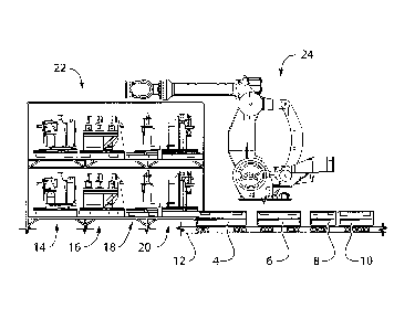
[0024] FIG. 3 is a side view of the system of FIG. la with the base modules
positioned in a tool mounting area;
100251 FIG. 4a is a top view showing a system according to an embodiment of
the
instant invention, with base modules positioned in an assembly area for
assembling a
first product;
100261 FIG. 4b is atop view of the system of FIG. 4a, with the base modules
positioned in a tool mounting area for receiving tool cassettes for assembling
a second
product;
[0027] FIG. 4c is a top view of the system of FIG. 4a, with the base modules
positioned in the assembly area for assembling the second product;
[0028] FIG. 5 is a top view of an assembly line according to an embodiment of
the
instant invention;
[0029] FIG. 6 is an enlarged top view showing zone I and zone 2 of the
assembly line
of FIG. 5; and,
is [0030] FIG. 7 is a simplified flow diagram of a method of operating an
assembly line
according to an embodiment of the instant invention.
DETAILED DESCRIPTION OF THE DRAWINGS
[0031] The following description is presented to enable a person skilled in
the art to
make and use the invention, and is provided in the context of a particular
application
and its requirements. Various modifications to the disclosed embodiments will
be
readily apparent to those skilled in the art, and the general principles
defined herein
may be applied to other embodiments and applications without departing from
the
scope of the invention. Thus, the present invention is not intended to be
limited to the
embodiments disclosed, but is to be accorded the widest scope consistent with
the
principles and features disclosed herein.
[0032] FIG. la is a top view showing a system according to an embodiment of
the
instant invention in a first configuration for assembling a first product.
FIG. lb is a
6
CA 02753071 2011-09-22
709070cA
top view showing the system of FIG. la in a second configuration for
assembling a
second product. By way of a specific and non-limiting example, the system that
is
shown in FIGS. la and lb is implemented in a vehicle assembly line, and more
particularly in a truck frame assembly line. As such, FIG. la shows a
configuration of
the system during assembly of a truck frame for a F-150 regular cab with a
6.5' box
(frame shown at 2a), and FIG. lb shows a configuration of the system during
assembly of a truck frame for a F-150 regular cab with an 8' box (frame shown
at 2b).
[0033] The system that is shown in FIGS. la and lb includes a plurality of
moveable
bases 4-10, to which different tooling elements can be detachably mounted.
Guide
tracks or rails 12, or another suitable guiding structure, are provided along
the ground
beneath the moveable bases 4-10. The guide tracks 12 extend between an
assembly
area, which is shown in FIGS. la and lb, and a not illustrated tool mounting
area. A
driving system drives the moveable bases 4-10 between respective first
positions
shown in FIG. la for assembling the first product 2a, and respective second
positions
shown in FIG. lb for assembling the second product 2b. By way of a specific
and
non-limiting example, the driving system 12 is a servo controlled, rack and
pinion
drive system. The drive system is controlled by a programmable logic
controller
(PLC), or by another suitable controller unit or a plurality of separate
controller units.
[0034] Referring now to FIG. 2a, shown is a side view of the system of FIG. la
with
the base modules 4-10 located in the product assembly area. During use, the
base
modules 4-10 are guided along the guide track 12 in the direction of the
double-
headed arrows in order to support assembly of the product frame 2a or 2b. The
system
that is shown in FIG. 2a includes a plurality of tooling elements 14-20, each
of the
tooling elements 14-20 being detachably mounted to a respective one of the
base
module 4-10. In the example that is shown in FIG. 2a, each tooling element 14-
20
includes a fixture for securing frame components in position for being welded
or
riveted etc. by robots, which are located adjacent to the product assembly
area.
[0035] The plurality of tooling elements 14-20, in aggregate, function in a
manner that
is analogous to a dedicated tool mounted on a single, fixed base in a typical
assembly
line of the prior art. However, since each tooling element of the plurality of
tooling
elements 14-20 has a cassette (modular) construction, the individual tooling
elements
7
CA 02753071 2011-09-22
709070CA
can be mounted onto separate base modules and variably spaced one from
another.
As is shown in FIG. 2b, for a representative base module 8 and tooling element
18, the
PLC 30 controls not only the position of the moveable bases 4-10 but also the
function of the tooling elements 14-20, such as for instance controlling which
clamps
to fire and which clamps to release, etc. As is shown in FIG. 2c, in an
enlarged view
of a portion of the representative base module 8 and tooling element 18, a
mounting
structure 34 of tooling element 18 detachably engages a complementary mounting
structure 36 of the base module 8, thereby securing the tooling element 18 to
the base
module 8 and completing a communication pathway between the PLC 30 and the
tooling element 18. As such, commands from the PLC 30 pass up to the tooling
elements 14-20 via respective base modules 4-10.
[0036] FIG. 3 is a side view showing the system described above with reference
to
FIGS. la-2c with the base modules positioned in a tool mounting area. Tooling
elements 14-20 are stored on robot accessible shelves 22, which are located
adjacent
to the tool mounting area. An industrial robot 24 is also provided adjacent to
the tool
measuring area. During use, the base modules 4-10 are moved along guide track
12
from the product assembly area to the tool mounting area, which is close to
the robot
24. Subsequently, using the robot 24, tooling elements 14-20 are transferred
onto and
detachably mounted to respective ones of the base modules 4-10. The particular
tooling elements 14-20 that are mounted onto the base modules are selected in
dependence upon the product that is to be assembled. Under the control of PLC
30,
tooling elements 14-20 are removed from base modules 4-10 and replaced with
different tooling elements 14-20 in an automated fashion. When it is necessary
to
retool an assembly line in order to stop assembling one product and begin
assembling
a different product, the base modules 4-10 are moved from their respective
positions
in the product assembly area, into the tool mounting area where new tooling
elements
are detachably mounted onto the base modules 4-10, and then returned to their
respective positions in the product assembly area. Performing this series of
steps
takes a robot 24 at each station approximately live minutes or less.
Accordingly, an
entire assembly line can be retooled to produce a different product in a
manner of
minutes.
8
CA 02753071 2011-09-22
709070CA
[0037] FIGS. 4a to 4c illustrate in greater detail the steps that are
performed during
retooling of one assembly line station. It should be noted that similar steps
arc
performed substantially simultaneously at each assembly line station of the
assembly
line. FIG. 4a is a top view showing a system according to an embodiment of the
instant invention, with the base modules 4-10 positioned in an assembly area
for
assembling a first product. In FIG. 4a, the base modules 4-10 are at
predetermined
positions A-D, respectively. FIG. 4b is a top view of the system of FIG. 4a,
with the
base modules 4-10 positioned in a tool mounting area for receiving tool
cassettes for
assembling a second product. FIG. 4c is a top view of the system of FIG. 4a,
with the
base modules positioned in the assembly area for assembling the second
product. In
FIG. 4c, at least some of the base modules 4-10 are located at a new
predetermined
position, offset from the respective predetermined position A-D, respectively.
For
instance, in the configuration that is shown in FIG. 4c the frame that is
being
assembled is a longer length variant compared to the frame that is assembled
using the
configuration shown in FIG. 4a.
[0038] Referring still to FIGS. 4a-4c, initially a first product having a
first length is
assembled, using the configuration of the system that is shown in FIG. 4a.
When it is
necessary to stop assembling the first product and begin assembling a second
product
having a second length longer than the first lern2th, then the moveable bases
4-10 are
moved out of the product assembly area along guide track 12 toward the robot
24.
The robot 24 replaces at least some tooling elements with different tooling
elements,
which are retrieved from storage locations on robot accessible shelves 22.
Finally, the
moveable bases 4-10 move away from the robot along guide track 12, and are
positioned at respective predetermined positions within the product assembly
area.
Optionally, when none of the tooling elements arc changed, the moveable bases
are
simply repositioned from their respective first predetermined positions A-D,
shown in
FIG. 4a, to respective second predetermined positions, shown in FIG. 4c.
[0039] FIG. 5 is a top view of an assembly line according to an embodiment of
the
instant invention. By way of a specific and non-limiting example, the assembly
line is
a truck frame assembly line, wherein: zone 1 is frame marriage; zone 2 is
frame
bracket application; zone 3 is for robotic piercing of critical holes; zone 4
is weld
inspection; and, zone 5 is dimensional inspection. The areas 50 along the
length of
9
CA 02753071 2011-09-22
709070CA
the assembly line are product assembly areas, and the areas 52 along the
length of the
assembly line are tool-mounting areas. Adjacent to at least some of the areas
50 is a
plurality of robots 54, which are for performing various functions for
assembling and
inspecting the product as it moves along the assembly line. Additional, larger
robots
56 are situated within the areas 52 between the areas 50. The larger robots 56
are for
detachably mounting tooling elements on the mobile bases, for transferring the
product from one assembly station to the next, and/or for inverting the
product as the
product moves along the assembly line.
[0040] Referring now to FIG. 6, shown is an enlarged top view showing zones 1
and 2
of the assembly line of FIG. 5. Guide tracks 12 extend between a product
assembly
area, which is located between robots 54, and a tool mounting area proximate
the
robot 56. Movable bases (only moveable base 4 has been labeled in order to
preserve
the clarity of the drawing) are positionable at different locations along the
guide tracks
12, for supporting assembly of different products. The robots 56 are for
detachably
mounting tooling elements on the mobile bases, for transferring the product
from one
assembly station to the next, and/or for inverting the product as the product
moves
along the assembly line.
[0041] Referring now to FIG. 7, shown is a method of operating an assembly
line
according to an embodiment of the instant invention. At 700 a tooling element,
in the
form of a cassette, is detachably mounted onto each one of a plurality of
moveable,
programmable bases. At 702, under the control of a programmable logic
controller,
the programmable bases are moved to respective First predetermined positions
for
assembling a first product. In particular, the moveable bases are driven along
a guide
track using a driving system. In order to stop manufacturing the first product
and
begin manufacturing the second product, the moveable bases are driven at 704
along
the guide track to a tool mounting area, and at 706 a robot is used to switch
out the
cassette tools on the moveable bases with other cassette tools that are stored
on robot
accessible shelves. Once the appropriate cassette tools are detachably mounted
onto
the moveable bases, then at 708 the moveable bases are driven along the guide
track
and stopped at respective second predetermined positions for assembling a
second
product. When the first and second products are different length variants, the
CA 02753071 2011-09-22
709070CA
respective first predetermined position is different than the respective
second
predetermined position for at least some of the moveable bases.
[0042] Using the systems and methods described above, it is possible to retool
an
entire assembly line having approximately 20 different stations in an
automated
fashion. The time that is required to retool the entire assembly line
typically is no
more than about five minutes.
[0043] It should be appreciated that the foregoing description is illustrative
in nature
and that the present invention includes modifications, changes, and
equivalents
thereof, without departure from the scope of the invention.
io
11