Note : Les descriptions sont présentées dans la langue officielle dans laquelle elles ont été soumises.
CA 02756363 2016-04-06
SELF LOCATING TIE BAR GUIDE FOR SASH LOCK TIE BARS
FIELD OF THE INVENTION
The invention relates generally to locking mechanism for casement windows and
doors. More specifically, the invention relates to self locating tie bar
guides used to secure
tie bars to the frame of a casement window or a door.
BACKGROUND
Multi point sash lock systems and multi point door lock systems are known.
These
systems typically have a single operating control, usually a lever or door
knob. The
operating control is linked to a tie bar that allows activation of the remote
locking points in
addition to the main locking point. Operation of the lever or knob causes the
tie bar to
move longitudinally, generally along the long axis of the window or the door.
Tie bar
guides are used to secure the tie bar to the sash or door preventing
transverse movement of
the tie bar while permitting the tie bar to move longitudinally.
Increasingly, self locating tie bar guides are utilized when tie bars are
installed in
casement windows. Self locating tie guide bars simplify the construction and
assembly of
casement windows and doors. Self locating tie bar guides are prepositioned at
desired
locations along the length of the tie bar until they are secured, typically by
screws, to the
sash, window
1
CA 02756363 2011-10-27
frame or door. Self locating tie bar guides eliminate the need to either pre-
drill holes that locate
the guide securing screws or to build jigs or fixtures to hold the guides in
place during the
assembly process. They thus facilitate and speed assembly of the locking
mechanism with the
window or door.
There are several tie bar systems that have self locating tie bar guides. Self
locating tie
bar guides are positioned along the tie bar at predefined locations and are
secured to the tie bar in
such a way as to stay in position until the tie bar guides are secured to the
sash and the
mechanism is operated.
There are generally two types of self locating tie bar guides. First, are
those that include
I() a tab pin or
some other feature that is frangible and that is broken off when the lock is
operated
for the first time and the tie bar is moved longitudinally. Second are those
that have a detent
feature that is engaged and disengaged every time the lock is operated. Each
of these designs has
certain short comings.
In systems that require a feature to be broken with the first operational
cycle of the lock,
the lock can be difficult to operate on the first cycle because sufficient
force must be applied to
sever the breakable feature. This is especially true when multiple locking
points are used. Very
often, the first operator of the lock is a homeowner. Homeowners commonly
assume that there ,
is something wrong with the window when it is difficult to operate the lock
mechanism the first
time Alternately, they may believe that a part of the lock mechanism not
intended to break has
been broken when they initially operate the lock. This can lead to increased
warranty claims and
dissatisfaction on the part of the homeowner
-
2
CA 02756363 2011-10-27
An additional concern that arises with systems that have a breakable feature,
is that a
broken off piece, when it is separated, can become free and lodge in some
moving part of the
lock mechanism. This can cause binding, noise or other problems which can also
lead to
increased warranty claims and homeowner dissatisfaction.
In the case of systems that have a permanent detent feature which engages and
disengages every time the lock is operated, the detent can be felt every time
the locked is cycled.
This prevents smooth operation of the lock hardware which is generally
desirable.
One example of prior art breakaway pin designs includes a tab on a plastic tie
bar guide
that engages in a notch on the steel tie bar to position the guide. The tab
breaks away when the
lock is first cycled. Another example of a prior art tie bar system uses a
small tab to hold a t-
shaped guide into a c-shaped tie bar_ When the tie bar guide is secured with a
screw, a shoulder
of the mounting screw pushes the location tab into a recess in the tie bar
guide. This allows the
tie bar to slide freely once installed.
Another prior art approach uses a leg with a post that fits into a hole in the
tie bar guide.
When the lock is first cycled, the post is forced out of the hole by movement
of the tie bar and
forces the leg upward. This causes the leg to yield or break at a weak point
built into the leg.
After the material of the leg has yielded, there is no downward pressure on
the post and the post
does not reengage into the hole, thereby freeing the tie bar for use. Another
prior art device
includes a dual tie bar guide with a breaking tab. The tab is fastened to the
tie bar at a lock roller
rivet. When the lock is operated for the first time, two small attachment
points break allowing
the tie bar to travel freely. The tab remains attached to the tie bar.
3
CA 02756363 2011-10-27
Accordingly, there is still room for improvement in the design of self
locating tie bar
guides.
SUMMARY OF THE INVENTION
The invention solves many of the above discussed problems by providing a self
locating
tie bar guide that has a locating tongue that holds the guide in place on the
tie bar prior to
installation. The locating tongue releases when the guide is secured to the
frame. No parts are
broken during the release. The release of the tongue permits free operation of
the tie bar. The
present invention does not require the lock to be cycled to release or break
the locating tab. This
allows free movement of the lock from the very first cycle. In addition, there
are no broken or
frangible pieces produced that can lodge in and interfere with operation of
the locking
mechanism.
The tie bar guide according to an embodiment of the invention has a generally
u-shaped
design which allows it to be snapped onto a tie bar. The open end of the u-
shape is smaller than
the thickness of the tie bar. This prevents the tie bar guide from falling off
the tie bar prior to
installation. In the center of an example tie bar guide is a tongue with a
roughly hemispherical
bump on its tip that engages an opening in the tie bar. This prevents the tie
bar guide from
sliding along the length of the tie bar prior to installation. The tongue is
attached at its base to
one side of the u-shaped tie bar guide. Near the base of the tongue is a short
leg extending
perpendicularly outward from the tongue. When mounting screws are inserted and
tightened, the
U-shaped guide is forced closed. As the guide closes the leg under the tongue
contacts an
opposing wall of the u-shaped tie bar guide thus forcing the tongue away from
the tie bar and
lifting the hemispherical bump at the tip of the tongue out of the hole in the
tie bar.
4
In a typical installation, two or more tie bar guides are located along the
length of a
tie bar prior to installation. The holes in the tie bar are located so that
the self locating tie
bar guides are at desired locations along the length of the tie bar for
installation. The tie
bar is then placed against the installation surface to which it will be
attached and screws are
inserted through openings in each of the tie bar guides to secured to the tie
bar guides to the
window sash or door frame. Tightening of the screws causes the leg to contact
the opposite
wall of the tie bar guide forcing the tongue away from the tie bar and
releasing the
hemispherical bump from the hole in the tie bar thereby releasing the tie bar
for free
longitudinal movement relative to the tie bar guide.
The invention includes a self locating tic bar guide for usc with a tic bar of
a
locking mechanism for a window, the tie bar having prelocated openings located
thereon,
the tie bar guide comprising: a unitary body comprising a tie bar receiving
portion, a
locator engaging portion and a fastener receiving portion; the tie bar
receiving portion
comprising an upper portion and an opposing lower plate joined by a c-shaped
portion, the
upper portion being shiftable relative to the lower plate between an open
orientation in
which the tie bar is insertable into the tie bar receiving portion through a
gap defined
between the upper portion and the lower plate and a closed orientation in
which the upper
portion contacts the lower plate to prevent the tie bar from passing through
the gap, the tie
bar receiving portion defining a longitudinal passage therethrough, the
passage being sized
and shaped, when in the closed orientation, to slidably receive the tie bar
therein; the
locator engaging portion including a resilient tie bar engaging member that
engages at least
one of the prelocated openings when the tie bar receiving portion is in the
open orientation,
and that is resiliently biased toward and into the passage when the tie bar
receiving portion
5
CA 2756363 2017-12-06
is in the open orientation and is shifted away from the passage and disengaged
from the at
least one of the prelocated openings when the tie bar receiving portion is in
the closed
orientation, wherein the resilient tie bar engaging member further includes a
tongue portion
including a tie bar engaging bump, wherein the tie bar engaging bump is sized
and shaped
to engage at least one of the prelocated openings when the tie bar receiving
portion is in the
open orientation, wherein the tongue portion includes a tongue leg extending
away
therefrom toward the lower plate when the tie bar receiving portion is in the
open
orientation and being in contact with the lower plate when the tie bar
receiving portion is in
the closed orientation, and wherein contact of the tongue leg with the lower
plate shifts the
tie bar engaging bump out of engagement with the prelocated opening; and the
fastener
receiving portion defining at least one aperture therethrough and being
oriented such that a
received fastener passing therethrough abuts at least part of the fastener
receiving portion
and urges the tie bar receiving portion toward the closed position when the
fastener is
tightened.
The invention also includes a tie bar assembly for use with a window or door
locking assembly, comprising: a tie bar having a plurality of prelocated
openings located
thereon; at least one tie bar guide releasably secured to the tie bar at one
of the plurality of
prelocated openings; the tie bar guide comprising a unitary body comprising a
tie bar
receiving portion, a locator engaging portion and a fastener receiving
portion; the tie bar
receiving portion comprising an upper portion and an opposing lower plate
joined by a e-
shaped portion, the upper portion being shiftable relative to the lower plate
between an
open orientation in which the tie bar is insertable into the tie bar receiving
portion through
a gap defined between the upper portion and the lower plate and a closed
orientation in
6
CA 2756363 2017-12-06
which the upper portion contacts the lower plate to prevent the tie bar from
passing through
the gap, the tie bar receiving portion defining a longitudinal passage
therethrough, the
passage being sized and shaped, when in the closed orientation, to slidably
receive the tie
bar therein; the locator engaging portion including a resilient tie bar
engaging member that
engages at least one of the prelocated openings when the tie bar receiving
portion is in the
open orientation, and that is resiliently biased toward and into the passage
when the tie bar
receiving portion is in the open orientation and is shifted away from the
passage and
disengaged from the at least one of the prelocated openings when the tie bar
receiving
portion is in the closed orientation, wherein the resilient tie bar engaging
member further
includes a tongue portion including a tie bar engaging bump, wherein the tie
bar engaging
bump is sized and shaped to engage at least one of the prelocated openings
when the tie bar
receiving portion is in the open orientation, wherein the tongue portion
includes a tongue
leg extending away therefrom toward the lower plate when the tie bar receiving
portion is
in the open orientation and being in contact with the lower plate when the tie
bar receiving
portion is in the closed orientation, and wherein contact of the tongue leg
with the lower
plate shifts the tie bar engaging bump out of engagement with the prelocated
opening; and
the fastener receiving portion defining at least one aperture therethrough and
being oriented
such that a received fastener passing therethrough abuts at least part of the
fastener
receiving portion and urges the tie bar receiving portion toward the closed
position when
the fastener is tightened.
6a
CA 2756363 2017-12-06
BRIEF DESCRIPTION OF THE DRAWINGS
Fig. 1 is cross sectional view of casement window including three self
locating tie
bar guides according to an embodiment of the invention;
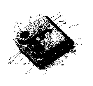
Fig. 2 is a perspective view of a self locating tic bar guide according to an
embodiment of the invention;
Fig. 3 is plan view of a self locating tie bar guide according to an
embodiment of
the invention;
Fig. 4 is a cross sectional view of a self locating tie bar guide according to
an
embodiment of the invention;
Fig. 5 is a perspective view of a self locating tie bar guide according to an
embodiment of the invention including extended supports;
Fig. 6 is a cross sectional view of an uninstalled self locating tie bar guide
secured
to a tie bar according to an embodiment of the invention; and
6b
CA 2756363 2017-12-06
CA 02756363 2011-10-27
Fig. 7 is a cross sectional schematic view of an installed self locating tie
bar guide
including a tie bar that has been freed according to an embodiment of the
invention.
DETAILED DESCRIPTION
Referring to Fig. 1, self locating tie bar guide 10 according to the invention
is typically
used with a casement window assembly 12. A casement window assembly generally
includes
sash 14 and frame 16. Sash 14 can be secured to frame 16 when sash 14 is
closed by activation
of locking mechanism 18. Locking mechanism 18 includes tie bar 20. Tie bar 20
is slidably
moveable to actuate locking mechanism 18 when handle 22 is manipulated.
Self locating tie bar guide 10 is temporarily secured to tie bar 20 at desired
locations by
its interaction with an aperture (not shown in Fig. 1, see Figs_ 6 and 7)
located in tie bar 20.
According to an embodiment of the invention depicted in Figs. 2, 3 and 4, tie
bar guide
10 generally includes body 24 having lower plate 26, upper portion 28 and c-
shaped portion 30.
Lower plate 26 is joined to upper portion 28 by e-shaped portion 30. Tie bar
guide 10 may be
formed, for example, of a polymer by a molding process or from resilient
metal.
Lower plate 26 generally includes planar mounting plate 32, defining screw
mounting
apertures 36. Lower plate 26 may further include extension 38.
Upper portion 28 generally includes tie bar bridge 40, screw bosses 42 and
tongue
portion 44. Tie bar bridge 40 extends between c-shaped portion 30 and screw
bosses 42 and may
be divided by tongue portion 44 as depicted in Figs. 2 and 3.
7
CA 02756363 2011-10-27
Lower plate 26, upper portion 78 and c-shaped portion 30 together define and
surround
tie bar passage 46 as can be seen in Fig. 4. Tie bar passage 46 is sized to
slidably receive tie bar
20 therein as can be seen in Fig. 6. Tie bar passage 46 is sized and shaped to
permit sufficient
freedom of movement for tie bar 20, once installed on a window or door, to
longitudinally slide
while holding tie bar 20 substantially in a transverse position with minimal
transverse movement.
In the embodiment depicted in Figs. 2-4, screw bosses 42 define upper screw
mounting
apertures 48. Lipper screw mounting apertures 48 are aligned with screw
mounting apertures 36
so that a screw or other fastener (not shown) inserted therethrough passes
through both upper
screw mounting apertures 48 and screw mounting apertures 36 to secure tic bar
guide 10 to sash
14.
In this example embodiment, tongue portion 44 is positioned within tongue
opening 50,
which is formed through upper portion 28 and tie bar bridge 40. Tongue portion
44 includes
tongue support 52, tongue arch 54 and tongue end 56. Tongue support 52
supports tongue arch
54, which in turn supports tongue end 56. Tongue support 52 extends into
tongue opening 50
from recessed portion 58, which in this example embodiment is located
generally between screw
bosses 42.
Referring particularly to Fig. 2 and Fig. 4; in the depicted example
embodiment, tongue
arch 54 rises above tongue support 52 and tongue end 56.
Referring particularly to Fig_ 4, tongue support 52 presents tongue leg 60,
which extends
downwardly toward lower plate 26 when tie bar guide 10 is in an open
orientation and not
secured by fasteners. On the underside thereof, tongue end 56 presents plateau
62 and tie bar
engaging bump 64. Tie bar engaging bump 64 may have a hemispherical or
partially spherical
8
CA 02756363 2011-10-27
shape as depicted in Fig. 4 or another shape. When in a relax state or open
orientation, in this
example embodiment, self locating tie bar guide 10 presents gap 66 between
lower plate 26 and
upper portion 28 in the vicinity of screw bosses 42.
Referring to Fig. 5, tie bar guide 10 in accordance with another embodiment of
the
invention, may include locating legs 68 extending outwardly away from lower
plate 26.
Locating legs 68 may include u-shaped locating legs 70 and/or linear locating
leg 72 as depicted
in Fig. 5. Locating legs 68 may assume other shapes as well.
Referring to Fig. 6, a cross sectional view of tie bar guide 10 is shown along
with tie bar
20. Tie bar engaging bump 64 is engaged in opening 74 of tie bar 20.
Referring to Fig. 7, a schematic cross sectional view of tie bar guide 10
after it has been
secured, with screws or other fasteners (not shown), is depicted along with
tie bar 20. Here tie
bar guide 10 is depicted in a closed orientation_ As depicted, upper portion
28 has been brought
into contact with planar mounting plate 32. Accordingly, tongue leg 60 has
contacted planar
mounting plate 32, thus forcing tongue portion 44 upward so that tie bar
engaging bump 64 has
been disengaged from opening 74 in tie bar 20. Thus, tie bar 20, whik being
generally secured
transversely, is free to move longitudinally with minimal friction by sliding
within tic bar
passage 46.
In operation, at least one self locating tie bar guide 10 is placed onto tie
bar 20 by
inserting tie bar 20 transversely through gap 66 and into tie bar passage 46.
Alternately, tie bar
guide 10 can be slid onto tie bar 20 longitudinally from one end of tie bar
20. Tie bar guide 10 is
then slid along tie bar 20 until tie bar engaging bump 64 engages opening 74
in tie bar 20. As
many tie bar guides 10 are desired are placed onto tie bar 20 at prelocated
openings 74. Tie bar
9
CA 02756363 2011-10-27
20 is provided with at least as many openings 74 along its length as the
desired number of tie bar
guides 10 that it is desired to use to secure tie bar guides 10 along the
length thereof. Openings
74 are located at the desired locations of tie bar guides 10 relative to tie
bat 20 when tie bar 20 is
secured to casement window assembly 12.
Tie bar 20 with self locating tie bar guides 10 thereon is then placed against
a sash 14 in a
desired mounting location.
Referring to Figs. 6 and 7, mounting screws (not shown) are inserted through
upper screw
mounting apertures 48 and screw mounting apertures 36 and tightened by driving
them into sash
14, or other desired mounting location, As screws (not shown) are tightened,
upper portion 28 of
tie bar 10 is drawn toward lower plate 26 of tie bar guide 10. During this
Process c-shaped
portion 30 and tie bar bridge 40 flex. As upper portion 28 is drawn against
lower plate 26,
tongue leg 60 contacts lower plate 26 and is forced upward relative to upper
portion 28 against
the resilient bias of tongue support 52 and tongue arch 54. At the same time,
tie bar engaging
bump 64 on tongue end 56 is lifted out of opening 74 in tie bar 20. Once tie
bar engaging bump
64 is disengaged from opening 74, tie bar 20 is free to slide longitudinally
within tie bar passage
46. Thereafter, when locking mechanism 18 is actuated by the movement of
handle 22, smooth
unrestricted operation is achieved immediately from the first operational
cycle. Further, no
broken off parts are released that can possibly become lodged in locking
mechanism 18 and
interfere with its proper and unrestricted operation. =
10
CA 02756363 2016-04-06
The scope of the claims should not be limited by the illustrated
embodiments set forth herein, but should be given the broadest interpretation
consistent
with the description as a whole.
11