Note : Les descriptions sont présentées dans la langue officielle dans laquelle elles ont été soumises.
1-0&27
WO 2010/109428 PCT/IB2010/051293
MODULAR, PREFABRICATED RADIANT PANEL WITH INTEGRATED HEADERS
DESCRIPTION
FIELD OF THE INVENTION
The present invention refers to a modular, prefabricated
radiant panel for the conditioning of inner spaces, i.e. to a
panel which is fully factory-assembled and ready for installa-
tion, designed to allow fast hydraulic connection to other simi-
lar panels and to the main pipes for the supply and return flow
of the thermal carrier fluid, provided with a finished front
surface and, finally, easy separable into panel submultiples. In
particular the invention concerns the connection problems of the
panels to the main pipes of the heat-carrying fluid which con-
nect the panels to the central system for hot/cold water produc-
tion.
STATE OF THE PRIOR ART
Radiant panels for room conditioning have experienced a
remarkable development over the last few years and are currently
one of the most interesting technical solutions to accomplish
room conditioning which associates excellent performance with
the opportunity of fast installation, substantially free from
brickwork, and which can hence be easily employed also in al-
ready existing buildings.
The best radiant panels of this type normally have a rear,
thermally insulating layer and a front layer with mechanical
strength and good thermal conductivity, such as for example
plasterboard. Inside, or in contact with, said front layer one
or more coil pipes are furthermore housed, wherein the heat-
carrying fluid is caused to circulate. The coil pipes of the
panels are finally connected to external supply and return head-
ers which supply the panels with the water coming from the cen-
tral system for hot/cold water production, to accomplish a radi-
ant-surface conditioning system.
A panel of the above-specified type, which furthermore has
extremely interesting submodularity features resulting in high
flexibility of installation, is the one disclosed in EP-1004827.
Unlike the previously known panels, as a matter of fact the coil
1
1-0&27
WO 2010/109428 PCT/IB2010/051293
pipe in the panel disclosed by this patent is divided into a
plurality of separate and juxtaposed circuits, independently
connected to the headers of the heat-carrying fluid. Due to this
construction it is possible to divide the panel, in a modular
way, into parts of a height suitable for any specific applica-
tion (over-door and under-window walls - stairwells), avoiding
the need to provide the manufacture of special pieces for this
purpose. This solution hence offers remarkable advantages, espe-
cially in terms of mounting flexibility, ease of hydraulic bal-
ancing, waste reduction, and of production standardisation,
which production can occur in one size only. In the light of
such remarkable advantages, in the practical use of such panel,
however, some drawbacks have also been detected.
Firstly, a complex and expensive manufacturing process,
especially due to the milling operation on the plasterboard re-
quired to form the coil- pipe-housing channel; as a matter of
fact, this operation determines the forming of a large amount of
plaster dust, the management of which remarkably complicates the
plants and further creates disposal problems. Secondly, there
are long installation times, since on the sides of each panel
pair a pair of supply/return pipes (headers) must be arranged,
and each individual circuit of the panel must then be connected
independently to such headers. The header area must be insulated
independently with a suitable shell previously applied to the
wall or to the ceiling and finally covered by a non-active
panel. This same need determines a third drawback, i.e. that the
strip of wall/ceiling taken up by the headers remains necessar-
ily passive to the radiant exchange, reducing the useful surface
which can be set aside for this function. The system for the
fastening of the known panels of this type further provides that
the fastening profiles be connected directly to the plasterboard
layer, hence determining a thermal bridge to the underlying
brickwork. Lastly, with this system it is not possible to have
panels wherein the front layer in sight is provided with differ-
ent and additional functions (for example: fireproof, sound-
absorbing, waterproof, architectural in general, etc.) different
2
1-0&27
WO 2010/109428 PCT/IB2010/051293
from the basic ones of mechanical support/heat conduc-
tion/external finish of the plasterboard, and this both because
the milling in the rear part of the panel can imply execution
problems with some types of material and, especially, because
such milling locally impairs the peculiar features of the panel,
which thus loses the original certification of compliance with a
certain quality standard.
PROBLEM AND SOLUTION
The object of the present invention is hence to overcome
the above-mentioned drawbacks, providing a panel structure which
allows - despite maintaining the improved submodularity perform-
ances of the above-described known panel - a construction proc-
ess free from dust, a simpler and faster installation method,
the removal of non-radiant passive surfaces and of thermal
bridges, and finally the opportunity to vary at will the compo-
sition and hence the functions of the front surface layer of the
panel in sight. This object is achieved by means of a radiant
panel having the features defined in claim 1. The dependent
claims define other preferred features of the invention.
BRIEF DESCRIPTION OF THE DRAWINGS
Further features and advantages of the invention will be
in any case more evident from the following detailed description
of a preferred embodiment of the same, which is provided here
purely as an example and must hence not be interpreted as limit-
ing the scope of the invention. Such embodiment is illustrated
in the attached drawings, wherein:
fig. 1 is a diagrammatic top plan view of the panel ac-
cording to the present invention;
fig. 2A, 2B, 2C are diagrammatic top plan views showing
the different options of dividing the panel into submultiples;
fig. 3 is a top plan view showing a radiant surface con-
sisting of a plurality of panels and panel submultiples accord-
ing to the present invention;
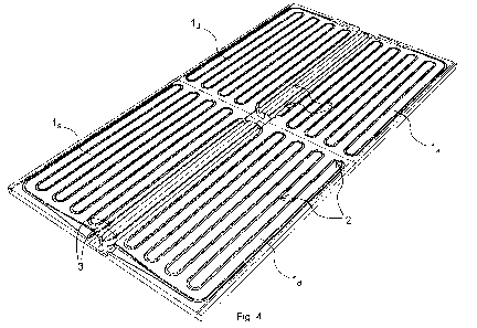
fig. 4 is a perspective view of the rear layer of ther-
mally insulating material of the panel of fig. 1, wherein the
grooves housing the radiant pipes and the supply headers are
3
1-0&27
WO 2010/109428 PCT/IB2010/051293
shown;
fig. 5 is a view similar to fig. 4, but comprising the ra-
diant pipes and respective supply headers positioned in their
housing grooves, showing, at an enlarged scale, the detail of
the lateral area housing the hydraulic connections between radi-
ant pipes and headers;
fig. 6 is a view similar to fig. 4, but comprising the ra-
diant pipes and respective supply headers positioned in their
housing grooves, showing, at an enlarged scale, the detail of
the central area where radiant pipes and headers are arranged
superposed; and
fig. 7 is an enlarged exploded view, in a cross-section,
of one of the hydraulic connections shown in fig. 5.
DETAILED DESCRIPTION OF THE PREFERRED EMBODIMENT
The radiant panel according to the present invention has a
sandwich-like structure known per se, comprising a rear layer of
thermally insulating material and a front layer provided with
mechanical strength, thermal conductivity, and surface-finishing
features suited to the specific application. As material for the
forming of the rear layer, synthetic materials can be used, such
as foamed plastic materials, such as polystyrenes or polyure-
thanes, or materials of a natural origin, such as cork. As mate-
rial for the forming of the front layer, various types of com-
posite layers having various functions can be used, preferably
fibre-reinforced, such as for example plasterboard, fibreboard,
asbestos cement, waterproof materials, sound-absorbing materi-
als, materials of a natural origin (wood) or other similar mate-
rials. The two layers are coupled with each other by gluing and
pressure, according to standard, equally widely-known proce-
dures. For simplicity's sake, in the figures 1, 2 and 3 of the
attached drawings the front finish layer is shown in a see-
through representation, i.e. with the edges only, to allow a
clear vision of the conformation of the rear layer and of the
corresponding pipes, in which layer in fact the present inven-
tion is essentially integrated, the front layer having been left
with the only function - known per se - of mechanical support
4
1-0&27
WO 2010/109428 PCT/IB2010/051293
and external surface finish.
Unlike the above-described known-art panels, wherein the
radiant pipe was embedded in the front finish layer in order to
achieve better heat transfer, in the panel according to the pre-
sent invention radiant pipes are arranged within suitable coil
grooves 2, preformed by moulding or otherwise formed in the
layer 1 of thermally insulating material, for example according
to the preferred drawing shown in fig. 4, which functional fea-
tures will be described below. Advantageously - both from the
point of view of manufacturing costs and of the modular divisi-
bility of the panel - layer 1 may not be in one piece but con-
sists of four (two) distinct rectangular elements, obtained by
ideally dividing the panel along the two (one) median lines
thereof, and hence of identical size. The preferred arrangement
of grooves 2 within the above-said four rectangular elements
forming layer 1, as shown in fig. 4, is such as to determine
only two different types of said elements, defined as right one
(1d) and left one (1s), respectively, with reference to the di-
rection of an observer looking at the panel from one of its mi-
nor bases, such elements being then positioned as shown in fig.
1 to form the entire rear layer 1.
For the purpose of improving the thermal conductivity of
the radiant pipe, before introducing the pipes into the respec-
tive grooves, the elements forming rear layer 1 are coated - in
correspondence of the surface on which grooves 2 are formed -
with a continuous metal layer, preferably of aluminium, which
extends also into said grooves, thereby positively contributing
to heat transfer from the radiant pipe which is inserted into
said grooves to the front finish layer of the panel.
The grooves formed in elements 1s and 1d are of two types
and precisely: grooves 2 for the housing of a radiant pipe 4,
for example a pipe having an 8-mm diameter; and grooves 3 for
the housing of headers 5 for the supply of the panel, for exam-
ple a pipe having a 20-mm diameter. Grooves 2 have a coil-shaped
structure extending to evenly cover the entire panel surface,
while grooves 3 are rectilinear and extend side-by-side on the
5
1-0&27
WO 2010/109428 PCT/IB2010/051293
opposite side of a median line of the panel and for the entire
length of the same. In the embodiment shown, said median line is
the one having the greatest extension, but of course a solution
is also possible wherein the grooves 3 of headers 5 extend along
the minor median line, i.e. in a crosswise direction to the lon-
gitudinal direction of the panel. Preferably, grooves 3 are ad-
jacent to the median line of the panel. The special groove pat-
tern described above, as better explained in the following, al-
lows to perform two particular functions: on the one hand allow-
ing to separate the panel in functionally independent parts, and
on the other hand gathering the hydraulic connections in re-
stricted, easyly accessible area located at the opposite sides
of the panel and in the centre thereof, making installation ex-
tremely easy and quick.
As a matter of fact, according to one of the main features
of the panel of the invention, said panel comprises inside and
integrated in rear layer 1, in addition to radiant pipes 4, also
headers 5 intended to supply the panel itself and the panels ad-
jacent thereto in the direction of the headers. As a matter of
fact, said headers are on the one hand connected hydraulically,
already during manufacturing, to the radiant pipes 4 of the
panel to supply them with the thermal carrier fluid and, on the
other hand, they can be connected hydraulically, during instal-
lation, to corresponding headers 5 of adjacent panels, as better
detailed in the following, to build the network of pipes which
supplies the radiant surface comprising the panels of the inven-
tion.
In the preferred embodiment shown in the drawings, the
grooves 2 intended to house pipes 4 develop along a path shaped
as side-to-side spirals which extends first on an element 1d,
and then uninterruptedly - through a semi-circular connection
portion arranged below the grooves 3 of the headers, in the
proximity of the centre of the rear layer 1 - on an element 1s,
adjacent to element 1d along the major side thereof, so that the
pattern of the grooves 2 of one of the elements 1s is mirror-
like equal to that of the adjacent element 1d. It is thus possi-
6
1-0&27
WO 2010/109428 PCT/IB2010/051293
ble to arrange inside said groove 2, extending along two adja-
cent elements 1d and 1s, a single pipe 4 which hence affects one
half of the entire rear layer 1 and which has its two free ends
in correspondence of a central position of the short sides of
said layer 1, where such ends are connected to headers 5, by
means of the connections schematically indicated in figs. 1 and
2 and shown in greater detail in figs. 5 and 7.
In said drawings it is possible to notice that such con-
nections comprise a T-junction 6 which is connected, by pressure
and by a ring nut connection, respectively, to a header 5 and to
a radiant pipe 4, the other end of the T-junction 6 facing out-
wards of the panel - but without projecting outside the panel
perimeter - with a male fast-engagement means into which a fe-
male sleeve 7 can be sealingly snap-inserted. The structure of
sleeve 7 is clearly visible in the cross-section drawing of
fig.7, and has been designed so as to have minimum lateral bulk
and to simultaneously comprise means for steady engagement with
T-junction 6, in the shape of a pair of elastic flaps 7a apt to
engage with corresponding projections 6a formed on T-junction 6.
Sleeve 7 is supplied both in the double-female version shown in
figs. 5 and 7, used for the connection between the headers 5 of
two adjacent panels as well as for the connection of a panel
comprising a single connection pipe, and in a one-side closed,
single-female version, used instead for the sealing of the head-
ers 5 of the panels arranged in a perimeter position.
In general, the section shape of grooves 2 is such as to
allow the introduction therein of pipes 4 with slight interfer-
ence, so as to improve the heat exchange between the pipe and
the aluminium layer which covers said grooves. On the contrary,
grooves 3 have such a transversal dimension to house headers 5
with slight clearance, and this in order to allow an easy axial
displacement of said headers during the fitting operations, as
well as the movements thereof determined by the thermal dila-
tions during the use of the panel. However, in correspondence of
the end portions of pipes 4 (fig. 5) and of the semicircular ar-
eas for the passage of said pipes 4 between adjacent elements
7
1-0&27
WO 2010/109428 PCT/IB2010/051293
1d, 1s (fig.6), also grooves 2 have a wider transversal dimen-
sion which allows a clearance of the pipe sufficient for the
fitting operations. In particular, in correspondence of the end
branches of pipes 4 which connect to joints 6, grooves 2 have a
V-shape of a progressively larger width towards the centre of
the panel, as clearly visible in figs. 4 and 5, to allow the
transversal displacement of said end branches consequent to the
axial displacement of headers 5 during the fitting operations of
joints 6, which will be described further below.
As mentioned in the initial portion of the present de-
scription, the structure of the panel of the present invention
is a sandwich-like structure comprising a thermally insulating
rear layer 1 and a front finish layer in sight. Since, as seen
above, the radiant pipes 4 and the headers 5 are fully housed
inside the thermally insulating layer 1, no processing, and in
particular no milling, needs to be carried out on the front
layer, thereby dramatically simplifying the panel manufacturing
process, and allowing the production of panels provided with an
outer finish layer having different nature, thickness and type
so that the finished radiant panel may offer, in addition to
thermal-type performances, also those mechanical and surface
features which are more in keeping with the specific project in
which the radiant panel is inserted, thus meeting better the
various architectural requirements.
The manufacturing process of the radiant panel according
to the present invention hence comprises a first phase, wherein
individual elements 1d, 1s are manufactured starting from the
above specified materials, with forming or moulding processes
well known per se which allow the forming of grooves 2 and 3.
Such elements are hence coated with an aluminium layer which ex-
tends into said grooves. In a second phase, groups of four of
said elements - two of type 1d and two of type 1s - are moved
close and coupled with each other, possibly with temporary
fastening systems (pins, adhesive tapes, templates, etc.), to
form the rear layer 1 of a panel. Two pipes 4 are then arranged
in the two grooves 2, which are so formed in the two halves of
rear layer 1, respectively, and hence, two headers 5 are aranged
8
1-0&27
WO 2010/109428 PCT/IB2010/051293
layer 1, respectively, and hence, two headers 5 are aranged in
grooves 3. Pipes 4 and headers 5 are hence mutually connected,
by means of joints 6, in correspondence of the central area of
the short sides of the panel, all said tubes, headers and con-
nections being entirely comprised within the panel perimeter.
Finally, in a third phase of the manufacturing process, on the
rear layer of the thus completed panel, a front layer of the de-
sired type is arranged, by arranging in between a suitable layer
of thermally conductive adhesive, then pressing the two layers
of the panel until adhesive reticulation is obtained and there-
fore a steady and final coupling between the layers.
In order to ease the subsequent operations of hydrauli-
cally connecting the panels on site, the front layer has suit-
able windows 8 opening into the rear layer 1, for example in the
crescent shape shown by discontinuous lines in figs. 1 and 2, in
correspondence of the end portion of said headers 5,i.e., in the
preferred embodiment, in the central portion of the two opposite
short sides of the panel, where the internal and external hy-
draulic connections of the panel are preferably gathered, as
stated above,. Once the connection has been established, windows
8 will be closed by introducing therein corresponding inserts,
possibly already obtained while cutting the front layer, so as
to restore the continuous outer surface of the panel. Said in-
serts can be joined to the panel surface by plastering or remain
as removable inserts. Conveniently, the rear layer 1 comprises a
further groove, substantially parallel to the grooves 3, which
ends in said opposed windows 8 and is apt to house electrical
cables for supplying electric appliances or other services which
nay be provided in, or near to, a radiant wall comprising the
panels of the invention.
As stated above, the particular structure of the radiant
panel allows both the integral use thereof, and the use of modu-
lar submultiples of the same. Such submultiples can be obtained
by dividing a panel according to its shorter median line (fig.
2A), according to its longer median line (fig. 2B) or, finally,
by further dividing the two above-said submultiples according to
9
1-0&27
WO 2010/109428 PCT/IB2010/051293
a median line perpendicular to the one of the first division
(fig. 2C). The panel division operation occurs very simply due
to the fact that the rear layer already consists of four mutu-
ally adjacent, independent elements 1d and 1s. Therefore, by in-
serting a cutter, or other suitable cutting means, into the gap
between two adjacent elements 1d, 1s it will be possible to en-
grave the front finish layer of the panel and cut off headers 5,
pipes 4 or both such elements, depending on whether the submul-
tiple one aims to obtain is the one shown in figs. 2A, 2B or 2C,
respectively. Regardless of the type of cutting, once the pipes
have been severed and the front layer has been engraved with a
bevel line, the panel is easily divided by breaking along said
bevel line.
Preferably, elements 1d and 1s according to the present
invention are formed in the 120 x 60 cm size, so as to allow the
coupling of four elements with a front layer easily available on
the market in the standard size of 120 x 240 cm. The finished
radiant panel will keep this same size, remarkably easing re-
moval, transport and installation operations, also due to the
fact that - unlike the known panel described above, and as al-
ready highlighted above - it has no hydraulic connection element
projecting from the outer profile of the panel. As a matter of
fact, in the known panel described above, the loop pipes pro-
jecting laterally from the panel caused some drawbacks during
the loading and unloading operations on and off transport means
and containers and at the same time were prone to damage. These
drawbacks of known panels are now fully removed by the panel of
the invention.
The wall or ceiling installation of the panels according
to the present invention can be accomplished very quickly and
with freedom of positioning. As a matter of fact, the panel of
the invention is provided with a thermally insulating layer ex-
tending across the entire width of its surface and hence does
not have points of direct contact between the conductive front
layer and the brickwork or the metal fastening profiles; the
problem of the forming of thermal bridges is hence fully re-
1-0&27
WO 2010/109428 PCT/IB2010/051293
moved, which bridges are instead found in known-type products.
Moreover, the rear layer of the panel has no particularly impor-
tant point for fastening, not even in the presence of the median
lines in which elements 1d and 1s are mutually adjacent. The in-
staller is hence fully free to arrange the wall or ceiling fas-
tening profiles in the preferred way, without being forced to
follow any preset pattern, and he can provide to fit the panels
directly to the wall or to the ceiling where the space available
requires it and the insulating conditions of said supports allow
it.
Once the panels have been fastened to the support, possi-
bly using the submultiples shown in figs. 2 to optimise the cov-
ering area, the installer will provide, through windows 8, to
insert sleeves 7 between adjacent panels in correspondence of
the free exit opening of joints 6, causing headers 5 to slide
axially, first in one direction and then in the other, to obtain
the space sufficient for the introduction and locking of sleeves
7 on the two facing joints 6 of two neighbouring panels, obvi-
ously without any need to change the position of the panels
which can then be completely and finally installed on the wall
before fitting the hydraulic connections. Closed-bottom, single-
female sleeves 7 are then inserted at one end of each column of
headers 5 thus formed (on the right hand side in fig. 3), while
the other end of the same column is connected to supply pipes M
and return pipes R of the hot or cold water production plant,
both directly as illustrated in fig. 3, and indirectly by ar-
ranging in between two feeding main pipes arranged crosswise to
headers 5 or of connection pipes apt to link groups of panels to
said supply feeding headers, not shown in the drawings for sim-
plicity's sake.
When during the installation of a radiant surface submul-
tiple elements of the panel are also used, the pipe sections
which have been highlighted during the cutting operation are
provided with pressure or nut ring joints, fully identical or
similar to the ones illustrated above, with the possible addi-
tion of an outer header 5', as shown in fig. 3, necessary when a
11
1-0&27
WO 2010/109428 PCT/IB2010/051293
longitudinal submultiple of the type shown in figs. 2B or 2C is
used.
From the preceding description it should be clear how the
radiant panel of the present invention has fully reached the set
object, removing all the above described drawbacks of known-art
modular panels. As a matter of fact, by removing the milling of
the front layer of the panel, where the radiant pipes were nor-
mally arranged, an extremely simplified manufacturing process
completely free from dusts is obtained. Moreover, and for the
same reason, the front layer of the panel can be chosen at will,
depending on its desired mechanical features, finish features or
other features, without such features being deteriorated by
milling. Moreover, by providing passing-through, panel-
integrated headers, it is possible to accomplish during manufac-
ture a great deal of the required outer hydraulic connections
while the remaining part of the hydraulic connection can be fit-
ted once the panels are completely installed on the wall; in-
stallation procedure are so greatly simplified and the overall
installation procedure of a radiant surface formed by the panels
of the invention hence turns into a very simple and fast one.
Due to the particular mutual arrangement of the inner headers
and of the radiant pipes, it is finally possible to have excel-
lent panel submodularity - further improved by the preformed
cutting lines obtained by forming rear layer 1 using four sepa-
rate elements - thereby maintaining the high optimisation in the
installation operations typical of the panel of the above de-
scribed known art, however, without any drawback thereof.
Lastly, due to the fact that the rear layer of the panel is not
discontinuous and that the presence of gaps between the panels
to house the headers is no longer necessary, the presence of
non-radiant passive surfaces and of thermal bridges with the un-
derlying wall or ceiling is fully removed.
However, it is understood that the invention must not be
considered limited to the particular arrangement illustrated
above, which represents only an exemplifying embodiment thereof,
but that several variants are possible, all within the reach of
12
1-0&27
WO 2010/109428 PCT/IB2010/051293
a person skilled in the field, without departing from the scope
of protection of the invention, as defined by the following
claims.
13