Note : Les descriptions sont présentées dans la langue officielle dans laquelle elles ont été soumises.
CA 02758468 2011-10-12
WO 2010/122351 PCT/GB2010/050667
1
Improvements in or relating to composite structures
Field of the invention
The present invention relates to core materials used in the construction of
composite
structures such as wind turbine blades. In particular, the present invention
relates to
core materials adapted to drape in order to conform to the curvature of such
composite
structures, and to composite structures incorporating such core materials.
Background
Existing wind turbine blades are generally manufactured from reinforced
composite
materials. A typical blade is fabricated in two shells, which are subsequently
united to
form a single unit. The shells include at particular location sandwich panel
regions
having a core of lightweight material such as foam or balsa wood.
Different regions of a wind turbine blade are subject to different forces.
Consequently,
the thickness of the core generally varies across the blade for structural
reasons.
Typically, the core thickness ranges from 5 mm to 45 mm.
A prior art core 10 is shown schematically in Figure 1a. Referring to Figure
1a, the core
10 includes several parallel slits 12, which facilitate draping of the core 10
so that the
core 10 may conform to the curvature of the blade shell, as shown
schematically in
Figure 1 b. Different regions of a blade have different curvatures.
Consequently, the
core 10 may be required to drape to different extents in different regions of
the blade.
It is desirable to introduce radar absorbing material (RAM) into the composite
structure of
blades. One reason for this is that rotating blades have a radar signature
similar to that
of aircraft, which can make it difficult for air traffic control and other
radar operators to
distinguish between aircraft and wind turbines. Incorporating RAM into blades
ensures
that the resulting blades have a reduced radar signature that can be
distinguished easily
from aircraft, and which creates less unwanted events (also known as
"clutter") on the
screen of the radar operator.
Figure 1 b shows a known technique for incorporating RAM into a blade.
Referring to
Figure 1 b, a blade 14 includes a radar absorbing layer 16 close to its outer
surface. The
CA 02758468 2011-10-12
WO 2010/122351 PCT/GB2010/050667
2
drapable core 10 of Figure 1 a is provided inboard of the radar absorbing
layer 16, and a
radar reflecting layer 18 is disposed beneath the core 10. The RAM may be a
"circuit
analogue" (CA) absorber in which the radar absorbing layer 16 comprises a
circuit
provided on a suitable substrate, for example a glass-fibre cloth, and the
radar reflecting
layer 18 may suitably comprise a carbon cloth.
The separation between the radar absorbing layer 16 and the radar reflecting
layer 18 is
a key parameter for absorption performance, and must be carefully controlled
to achieve
a blade having the desired absorption properties. Such careful control of the
separation
of layers is made more difficult by varying geometry of the blade,
specifically the
abovementioned variation in core thickness.
Summary of the invention
According to a first aspect of the present invention, there is provided a
composite
structure comprising a functional layer and a core, the core comprising: a
first core layer;
a second core layer; and a functional interlayer disposed between the first
and second
core layers; wherein the first core layer is disposed between the functional
layer and the
functional interlayer; the thickness of the first core layer is substantially
uniform across
the composite structure; and the distance between the functional layer and the
functional
interlayer is substantially constant across the composite structure.
Hence, the invention resides in a split core arrangement in which the
thickness of the
core is divided between first and second core layers disposed about a
functional
interlayer.
Also in accordance with the first aspect of the invention, there is provided a
composite
structure comprising an outer surface and a core, the core comprising: a first
core layer;
a second core layer; and a functional interlayer disposed between the first
and second
core layers; wherein the first core layer is disposed between the outer
surface and the
functional interlayer; the thickness of the first core layer is substantially
uniform across
the composite structure; and the depth of the functional interlayer with
respect to the
outer surface is substantially constant across the composite structure.
CA 02758468 2011-10-12
WO 2010/122351 PCT/GB2010/050667
3
The composite structure may be of sandwich panel construction, in which the
core is the
sandwich panel core. In examples of the invention described herein, the
composite
structure forms part of a wind turbine blade. However, it will be readily
apparent that the
present invention is not only applicable to wind turbine blades, but may also
be
applicable to any composite structure in which it is desirable to maintain a
functional
layer at a substantially constant distance from another functional layer or at
a
substantially constant depth with respect to an outer surface the composite
structure.
If RAM is incorporated into the composite structure, the functional interlayer
may
comprise a RAM reflecting layer, for example a layer of carbon tissue. In
addition, the
functional layer of the composite structure may be, or comprise, a RAM
absorbing layer.
The RAM absorbing layer may be located close to the external surface of the
composite
structure. The RAM absorbing layer and the RAM reflecting layer are separated
by a
substantially constant distance by virtue of the first core layer of
substantially uniform
thickness. This ensures consistent RAM performance.
The total thickness of the core can be varied by varying the thickness of the
second core
layer without varying the thickness of the first core layer. Accordingly, the
thickness of
the second core layer may vary across the composite structure to vary the
overall
thickness of the core. As the thickness of the first core layer remains the
same for all
core thicknesses, consistent radar absorption performance can be achieved
across an
entire composite structure. Furthermore RAM design is less constrained by pre-
determined core thicknesses. Functionality is improved because the split core
design
has consistent RAM performance across all core thicknesses.
The core layers are preferably formed from a lightweight material. Suitable
materials
include open or closed cell structured foam, syntactic foam, balsa wood and
composite
honeycomb. The core is preferably of unitary construction. Preferably the core
is
prefabricated such that the functional interlayer is embedded within the core
prior to
fabrication of the composite structure. The core may be used in prepreg or
resin infusion
moulding, or in other compatible moulding schemes. For application in a wind
turbine
blade, the thickness of the first core layer is typically in the range of 10
to 15 mm and the
thickness of the second core layer is typically in the range of 5 to 35 mm.
These
thicknesses are suitable for absorbing aviation radar signals in the 1 to 3
gigahertz (GHz)
range. However, it will be appreciated that different thicknesses may be
required in
order to absorb higher or lower frequencies.
CA 02758468 2011-10-12
WO 2010/122351 PCT/GB2010/050667
4
The RAM absorbing layer may comprise a cloth substrate carrying a circuit
which may be
provided using conductive materials using known deposition techniques.. The
cloth may
be woven from glass or other suitable reinforcing fibres. Preferably the cloth
has a low-
movement weave so that fibre movement, which may lead to breaking of the
circuit
elements, is minimised. Plain weave is an example of a low-movement weave. In
examples of the invention described later, the cloth is plain weave E-glass.
As aforesaid, the composite structure may be a wind turbine blade.
Accordingly, the
inventive concept includes a wind turbine having such a blade, and a wind farm
comprising one or more such wind turbines.
The inventive concept also includes a wind turbine blade of sandwich panel
construction,
in which a core of the sandwich panel comprises: first and second core layers;
and
a radar reflecting layer disposed between the first and second core layers;
wherein the
thickness of the first core layer is substantially uniform across the wind
turbine blade,
such that the radar reflecting layer is maintained at a substantially constant
distance from
a radar absorbing layer of the wind turbine blade. The thickness of the second
core layer
may vary across the blade to vary the overall thickness of the core. The radar
absorbing
layer may have the same design across regions of the blade of varying core
thickness.
Furthermore, again, the inventive concept includes a wind turbine having such
a blade or
a wind farm comprising at least one such wind turbine.
It may be desirable to embed other functionality within the core. Whilst it
would be
possible to have two or more types of functionality at different locations in
the core, it is
desirable to have the functionality in the same location. For example, optical
fibres may
be included between the two core layers, either instead of or in addition to a
RAM
reflecting layer. In the context of wind turbine blades, the optical fibres
may be utilised in
measuring loads experienced at various locations in the blades. Conveniently,
any
embedded functionality is protected by the first and second core layers.
Also in accordance with the first aspect of the invention, there is provided a
core for a
composite structure, the core comprising: a first core layer; a second core
layer; and a
functional interlayer disposed between the first and second core layers;
wherein the first
and second core layers and the functional interlayer are bonded together as a
unitary
core material; and the first core layer is of uniform thickness across the
core. It will be
CA 02758468 2011-10-12
WO 2010/122351 PCT/GB2010/050667
appreciated that other preferred and/or optional features described above in
relation to
the composite structures are also applicable to this core, but for reasons of
conciseness
have not been repeated. For example: a RAM reflecting layer and/or optical
fibres may
be embedded in the core, and the thickness of the second core layer may vary
across
5 the core to vary the overall core thickness and hence to suit the structural
requirements
of a composite structure such as a wind turbine blade.
Curved composite structures such as wind turbine blades are fabricated on a
mould that
has a curved surface corresponding to the required curvature of the structure.
Depending
on the required curvature of the structure, the surface of the mould may have
regions of
concave and/or convex curvature. During lay-up of the curved structure, the
cores are
laid in the mould together with the other layers making up the structure. The
cores must
be sufficiently flexible so that they can drape in order to conform to the
curvature of the
mould, and hence the curvature of the resulting structure. To this end, the
cores
described above may be suitably adapted to facilitate draping as described in
more detail
below in relation to a second aspect of the invention.
It is important that any functionality incorporated in the interlayer region
remains intact
during manufacture of the core, during fabrication of the composite structure
and in use
of the composite structure. For example, in RAM applications when the
interlayer
includes a carbon cloth, it is undesirable to penetrate the carbon cloth
because that
would adversely affect its performance as a RAM reflector. Also, if optical
fibres are
included in the interlayer region, these must remain intact so that that they
can perform
their function.
To meet these challenges, a second aspect of the present invention resides in
a core for
a composite structure, the core comprising: a first core layer; a second core
layer; and
an interlayer region between the first and second core layers; wherein at
least one of the
first and second core layers has hinge portions that do not interrupt the
interlayer region.
The hinge portions facilitate draping of the core whilst maintaining the
continuity of the
interlayer region and of any materials disposed in the interlayer region. This
is important
for RAM applications because disrupting the continuity of a carbon cloth layer
would
adversely affect its RAM performance. This is also important when optical
fibres are
disposed in the interlayer region because the continuity of the optical fibres
must be
maintained so that they may perform their function.
CA 02758468 2011-10-12
WO 2010/122351 PCT/GB2010/050667
6
The hinge portions are a means of articulation that enhance the flexibility of
the first and
second core layers. The hinge portions may comprise lines of weakness or
locally-
thinned portions in the core layers. For example, the hinge portions may be
defined by
drape-promoting formations such as discontinuities, grooves, channels, slits
or slots in
the core layers. The hinge portions function as joints.
In preferred embodiments of the invention, slits are provided in the core
layers to
facilitate draping. The slits may be provided with or without removal of
material from the
core layers. A first plurality of slits may be provided in the first core
layer and a second
plurality of slits may be provided in the second core layer. The first
plurality of slits may
each extend into the first core layer to a depth not exceeding the thickness
of the first
core layer. Similarly, the second plurality of slits may each extend into the
second core
layer to a depth not exceeding the thickness of the second core layer.
Preferably the first
plurality of slits each extend into the first core layer to a depth that is
less than the
thickness of the first core layer. It is also preferred that the second
plurality of slits each
extend into the second core layer to a depth that is less than the thickness
of the second
core layer.
Thus, the first and second plurality of slits do not cross the interlayer
region.
Consequently, the core slitting scheme facilitates draping of the core whilst
maintaining
the continuity of the interlayer region.
Functionality may be embedded within the core. For example, the interlayer
region may
comprise optical fibres and/or a RAM reflecting interlayer such as carbon
tissue.
Conveniently, any such embedded functionality is protected by the first and
second core
layers. The core layers are preferably formed from a lightweight material.
Suitable
materials include open or closed cell structured foam, syntactic foam, balsa
wood,
composite honeycomb. The core is preferably of unitary construction.
The draping scheme is also advantageous for non-functional applications, i.e.
in which
the interlayer region does not include functionality such as a carbon cloth or
optical
fibres. For example, the core may be a bonded core in which first and second
core
layers are bonded together by an adhesive provided in the interlayer region -
i.e. an
"adhesive interlayer". Bonded cores are generally stronger than single layer
cores of
equivalent thickness, and the draping scheme facilitates draping without
penetrating or
CA 02758468 2011-10-12
WO 2010/122351 PCT/GB2010/050667
7
otherwise disrupting the continuity of the adhesive interlayer. Consequently,
draping is
facilitated in the bonded core without reducing the bond area or reducing the
bond
strength between the core layers.
In the following description, the terms "innermost" and "outermost" will be
used to refer to
regions of the core layers in terms of their relative dispositions with
respect to a radius of
draping curvature. It will become clear that a given core layer, for example
the first core
layer, can be both innermost and outermost in different regions of a composite
structure
in accordance with the local curvature of the composite structure.
When a core is draped in a mould during composite lay-up, one of the core
layers
becomes innermost with respect to a radius of draping curvature and the other
core layer
becomes outermost with respect to that radius of draping curvature. For
example, if the
second layer is innermost with respect to a radius of draping curvature in a
convex-
curved region of the mould, then the first layer will be outermost with
respect to that
radius of draping curvature; it follows then that the first layer will be
innermost with
respect to a radius of draping curvature in a concave-curved region of the
mould, and the
second layer will be outermost with respect to that radius of draping
curvature.
The curvature of a composite structure may vary across the structure. Indeed,
the
curvature may switch between concave and convex moving across the structure;
this is
true of modern wind turbine blades. Therefore, as mentioned above, a core
layer may
be innermost with respect to a radius of draping curvature in one region of a
structure
and outermost with respect to a radius of draping curvature in another region
of the
structure.
The hinge portions in the core layers may be suitably configured to obtain the
required
level of drape for a given core thickness as described by way of example
below. In this
respect, references to "low drape" are to situations where a radius of draping
curvature is
relatively large; and references to "high drape" are to situations where a
radius of draping
curvature is relatively small.
For low drape, the width and separation of the hinge portions in the first
core layer may
be similar to the width and separation of the hinge portions in the second
core layer.
CA 02758468 2011-10-12
WO 2010/122351 PCT/GB2010/050667
8
Higher levels of draping may be achieved by increasing the flexibility of the
core layers
and/or by increasing the ability of the core to shorten and/or lengthen to
achieve a given
radius of curvature. To this end, the size of the drape-promoting formations
in a region
of a core layer may be increased. When the drape-promoting formations are in
the form
of slits, the slits may be widened to increase their size.
If the thickness of an innermost region of a core layer is increased, then it
may be
necessary to increase the size of the drape-promoting formations in that
region of the
core layer in order to achieve a required level of draping.
Generally speaking, it is desirable to increase the separation between drape-
promoting
formations when increasing the size of the formations so that there is
sufficient core
material in a core layer to achieve the structural objectives of the core.
Drape-promoting formations in the core layers may have a V-shaped cross
section
(otherwise referred to herein as a "V-section") or a cross-section that
otherwise tapers
inwards towards the interlayer region. This may be desirable for preventing
excessive
resin ingress for a given drapability. For example, the movement capability of
a hinge
portion defined by a V-section slit is similar to the movement capability of a
hinge portion
defined by a parallel-sided slit having a slit opening of equivalent size.
However, the
volume of the V-section slit will be lower than the parallel-sided slit and so
resin ingress
is lower in the V-shaped slit whilst drapability of the core is similar.
V-section drape-promoting formations or formations that otherwise taper
towards the
interlayer region may also be desirable in regions of a core layer that, when
draped, will
be innermost with respect to the radius of draping curvature; this is to
prevent the drape-
promoting formations in these parts from closing up and hence tending to block
further
curvature when the core is draped. However, if such shaped formations are
provided in
outermost regions of a core layer, then these formations may widen undesirably
when
the core is draped.
Accordingly, it may be desirable to have drape-promoting formations of varying
profiles
across a given core layer. For example, V-section or otherwise suitably-
tapered drape-
promoting formations could be provided in regions of a core layer that will be
innermost
when draped, whilst non-tapered formations could be provided in regions of
that same
core layer that will be outermost when draped.
CA 02758468 2011-10-12
WO 2010/122351 PCT/GB2010/050667
9
From the examples above, it will be apparent that the drape-promoting
formations in the
first core layer may be different from the drape-promoting formations in the
second core
layer and/or the configuration of the drape-promoting formations in the first
core layer
may be different from the configuration of the drape-promoting formations in
the second
core layer. For example, one core layer may have V-section drape-promoting
formations
and the other core layer may have parallel-sided drape-promoting formations.
It will also be apparent that the drape-promoting formations may vary in type
and/or
configuration across the first and/or the second core layer. For example, at
least one
core layer may have regions that include V-section drape-promoting formations,
and
regions that include parallel-section drape-promoting formations.
The core may be of unitary construction, and may be in the form of discrete
panels or
sheets. The edges of the panels or sheets may be chamfered to provide
chamfered
joints between panels. Benefits of the chamfered edges are particularly acute
when
there is high drape.
Parallel drape-promoting formations may be provided in the core layers to
facilitate
draping in a single direction. Alternatively, the drape-promoting formations
may intersect
with one another, for example in a criss-cross pattern, to facilitate draping
in more than
one direction.
It will be appreciated that preferred and/or optional features of the second
aspect of the
invention are equally applicable to the first aspect of the invention and vice
versa. In
particular, the draping scheme described above in relation to the second
aspect of the
invention may be applied to facilitate draping in the cores described in
relation to the first
aspect of the invention.
Brief description of the drawings
Reference has already been made to Figures 1 a and 1 b of the accompanying
drawings
in which:
Figure 1 a is a schematic cross-sectional side view of a prior art foam core
provided with slits to facilitate draping; and
CA 02758468 2011-10-12
WO 2010/122351 PCT/GB2010/050667
Figure 1 b is a schematic cross-sectional side view of the foam core of Figure
1 a
draped between RAM absorber and reflector layers in a wind turbine blade.
In order that the invention may be more readily understood, reference will now
be made,
5 by way of example, to Figures 2 to 6, in which:
Figure 2a is a schematic cross-sectional side view of a split core comprising
first
and second core layers each provided with slits to facilitate draping of the
split
core during fabrication of a composite structure as shown in Figure 2b,
wherein a
10 functional interlayer is shown between the first and second core layers;
Figure 2b is a schematic cross-sectional side view of a composite structure
such
as a wind turbine blade, in which the split core of Figure 2a is shown in a
draped
configuration and disposed inboard of a functional layer of the composite
structure;
Figure 3a is a schematic cross-sectional side view of a split core similar to
the
split core of Figure 2a, but having a thicker second core layer;
Figure 3b is a schematic cross-sectional side view of a composite structure
such
as a wind turbine blade, in which the split core of Figure 3a is shown in a
draped
configuration and disposed inboard of a functional layer of the composite
structure;
Figure 4a is a schematic cross-sectional side view of a wind turbine blade of
sandwich panel construction and comprising a split core;
Figure 4b is an enlarged schematic cross-sectional side view of the blade of
Figure 4a in a region close to a rotor hub, in which region the split core has
a
relatively thick second core layer;
Figure 4c is an enlarged schematic cross-sectional side view of the blade of
Figure 4a in a region close to the blade tip, in which region the split core
has a
relatively thin second core layer;
CA 02758468 2011-10-12
WO 2010/122351 PCT/GB2010/050667
11
Figure 5 is a schematic cross-sectional side view of a bonded core comprising
first and second core layers joined together by an adhesive interlayer, the
first
and second core layers each comprising a plurality of slits to facilitate
draping;
Figure 6a is a schematic cross-sectional side view of a split core similar to
the
split core of Figure 2a, including labels denoting width of slits and
separations
between slits; and
Figure 6b is a schematic cross-sectional side view of the split core of Figure
6a,
in which the split core is draped in a convex-curved region of a mould, and in
which a radius of draping curvature is shown.
Detailed description
Figure 2a shows a split core 20 for use in the construction of composite
structures such
as wind turbine blades. Referring to Figure 2a, the split core 20 is of
unitary construction
and comprises a first core layer 22 and a second core layer 24, each of
lightweight core
material, for example foam. A functional interlayer 26 is disposed between the
first and
second core layers 22, 24. The three layers 22, 24, 26 are bonded together by
a suitable
adhesive such that the functional interlayer 26 is embedded within the
resulting core 20.
In this example, the functional interlayer 26 is a carbon cloth layer, which
functions as a
back reflector for radar, and is hereinafter referred to as a "RAM reflector
layer".
As shown in Figure 2b and described in more detail later, the split core 20 is
adapted to
drape in order to conform to the required curvature of the composite structure
in which it
is incorporated. That curvature is defined by the curvature of a mould (not
shown) in
which the split core 20 is laid up during fabrication of the composite
structure. Referring
to Figure 2b, the split core 20 is shown disposed inboard of a functional
layer 28 of a
composite structure 30, for example a wind turbine blade. In this example, the
functional
layer 28 is a radar absorbing layer, referred to hereinafter as a "RAM
absorber layer".
The RAM absorber layer 28 comprises a circuit provided on a layer of plain
weave E-
glass. The RAM absorber layer 28 is disposed close to an external surface (not
shown)
of the composite structure 30.
As described by way of background to the invention, the relative separation
between the
RAM absorber layer 28 and the RAM reflector layer 26 is a key design parameter
and
CA 02758468 2011-10-12
WO 2010/122351 PCT/GB2010/050667
12
affects RAM performance. In this example, the relative separation between the
RAM
absorber layer 28 and the RAM reflector layer 26 is determined by the
thickness of the
first core layer 22, which separates these two layers in the composite
structure 30. For a
given design of RAM absorber layer 28, consistent RAM performance is achieved
by
ensuring that the first core layer 22 is of substantially uniform thickness
across the
composite structure 30.
It will be noted that the split core 20 in Figure 2b is draped. Slits 32a, 32b
are provided in
the first and second core layers 22, 24 to promote draping in a way that is
described later
with reference to Figures 6a and 6b.
Ignoring the generally minimal thickness of the RAM reflector layer 26, the
total thickness
(T') of the split core 20 is the sum of the thickness of the first core layer
22 (t,') and the
thickness of the second core layer 24 (t 2'); i.e. T' = t 1' + t 2'-
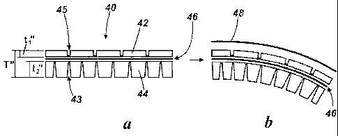
Referring now to Figure 3a, there is shown a split core 40 of unitary
construction and
comprising a first core layer 42, a second core layer 44 and a functional
interlayer 46 in
the form of a RAM reflecting layer disposed between the first and second core
layers 42,
44. The thickness of the first core layer 42 (t,") is identical to the
thickness of the first
core layer 22 (t,') of the split core 20 of Figure 2. However, the thickness
of the second
core layer 44 (t 2") is greater than the thickness of the second core layer 24
(t 2') of the
split core 20 of Figure 2. Hence, the total thickness (T") of the split core
40 of Figure 3 is
greater than the total thickness (T') of the split core 20 of Figure 2.
A comparison of Figures 2 and 3 shows that the total thickness T of the split
cores 20, 40
can be varied by varying just the thickness t 2 of the second core layer 24,
44; the
thickness t, of the first core layer 22, 42 can remain the same irrespective
of the total
core thickness T. The split core design therefore allows the total core
thickness T to vary
without affecting the separation between the RAM reflector layer 26, 46 and
the RAM
absorber layer 28, 48, which is determined by the thickness t 1 of the first
core layer 24,
44. Consequently, design of a uniform RAM solution is simplified irrespective
of the total
thickness T. This is in contrast to the prior art shown in Figure 1 b, which
requires a
different RAM absorber design for each core thickness. The split core 20, 40
of the
present invention reduces lay-up complexity, facilitates stock control and
eliminates the
risk of using an incorrect RAM cloth in a given region of the composite
structure.
CA 02758468 2011-10-12
WO 2010/122351 PCT/GB2010/050667
13
A wind turbine blade 50 of sandwich panel construction comprising a split core
52
substantially as described above is shown schematically in Figure 4a. The
blade 50
extends from a root end 54 connected to a rotor hub 56, to a tip end 58. As
shown in
Figures 4b and 4c, the split core 52 has a first core layer 60, a second core
layer 62 and
a radar reflecting interlayer 64 disposed between the first and second core
layers 62, 64.
A radar absorbing layer 66 is disposed close to the outer surface 68 of the
blade 50.
There is a need for greater structural strength at the root end 54 than at the
tip end 58.
Consequently, the core 52 is thicker at the root end 54 (Figure 4b) than at
the tip end 58
(Figure 4c). Referring to Figures 4b and 4c, the second core layer 62 is
relatively thick
(e.g. about 30 mm) in a region close to the root end 54 (Figure 4b) and
relatively thin
(e.g. about 5 mm) in a region close to the tip end 58 (Figure 4c). However,
the first core
layer 60 has the same thickness (e.g. about 10 mm) in both regions (Figure 4b
and
Figure 4c). Therefore, the separation between the RAM absorber layer 66 and
the RAM
reflector layer 64 is the same in both regions of the blade 50. This
facilitates uniform
RAM properties across both regions. Indeed, design of a RAM absorber for use
in
different regions of the blade 50 of different total core thickness is
simplified, provided
that the thickness of the first core layer 60 in these regions is the same.
Extending this
idea, a single design of RAM cloth can be used across the entire blade 50,
provided that
the first core layer 60 is of substantially uniform thickness across the blade
50.
It will also be noted that there is relatively high drape toward the root end
54 of the wind
turbine blade 50, and relatively low drape toward the tip end 58. To suit
these
characteristics, the slits in the second core layer 62 differ from one
location to the next,
whilst the slit configuration of the first core layer 60 remains the same.
Specifically,
where the second core layer 62 is relatively thick in the high drape region
near the root
end 54, the slits are relatively wide and are spaced further apart than in the
relatively thin
second core layer 62 near the tip end 58. The preferred relationship between
core layer
thickness, slit width and slit spacing is described in more detail below with
reference to
Figures 6a and 6b.
An additional benefit of the split core design is that the embedded RAM
reflector layer
26, 46, 64 is protected on both sides by the first and second core layers
respectively. In
further examples of the invention, which are not shown in the figures, other
materials
may be embedded in the core 20, 40, 52. For example, optical fibres may be
included in
the region between the first and second core layers (also referred to herein
as the
CA 02758468 2011-10-12
WO 2010/122351 PCT/GB2010/050667
14
"interlayer region"). In the context of wind turbine blades, the optical
fibres may be
utilised in measuring loads experienced at various locations in the blades.
Advantageously, the optical fibres would be protected by the split core
construction.
Referring back to the prior art core 10 shown in Figure 1 b, draping is
facilitated by the
slits 12 that extend through the majority of the thickness of the core 10. If
this draping
scheme was applied to the split core construction of Figures 2 to 4, then the
slits would
extend through the carbon cloth 26, 46, 64 and would disrupt its performance
as a RAM
reflector. Therefore, an alternative scheme has been developed for
facilitating draping of
the split core 20, 40, 52 without disrupting the continuity of the interlayer.
The alternative
draping scheme is described below with reference to Figures 2, 3, 5 and 6.
Referring back to Figure 2, a plurality of hinge portions 68 are provided in
the first and
second core layers 22, 24. The hinge portions 68 are defined by drape-
promoting
formations 70 in the form of slits 32a, 32b; specifically, each hinge portion
68 lies directly
underneath a respective slit 32a, 32b. A first plurality of slits 32a is
provided in the first
core layer 22, and a second plurality of slits 32b is provided in the second
core layer 24.
So as not to disrupt the continuity of the interlayer 26, the slits 32a, 32b
stop short of the
interlayer 26; expressed in other words, the first plurality of slits 32a each
extend into the
first core layer 22 to a depth that is less than the thickness t 1 (Fig 2) of
the first core layer
22, and the second plurality of slits 32b each extend into the second core
layer 24 to a
depth that is less than the thickness t 2 (Fig 2) of the second core layer 24.
This
configuration of slits facilitates draping without slitting the RAM reflector
layer 26, which
would disrupt its RAM performance.
The draping scheme described above is also advantageous for non-functional
applications, i.e. in which the interlayer does not comprise functionality
such as a carbon
cloth or optical fibres. For example, the draping scheme may be used in bonded
cores,
in order to facilitate draping without cutting through an adhesive layer(s)
between the
core layers, and hence without reducing the bond area or reducing the bond
strength
between the core layers. Bonded cores are generally stronger than single layer
cores of
equivalent thickness.
An example of a bonded core 80 is shown in Figure 5. Referring to Figure 5,
the bonded
core 80 comprises a first core layer 82 and a second core layer 84 bonded
together by
an adhesive interlayer 86. To facilitate draping, the first core layer 82
includes a first
CA 02758468 2011-10-12
WO 2010/122351 PCT/GB2010/050667
plurality of slits 88a and the second core layer 84 comprises a second
plurality of slits
88b. The first plurality of slits 88a each extend into the first core layer 82
to a depth that
is less than the thickness of the first core layer 82, whilst the second
plurality of slits 88b
each extend into the second core layer 84 to a depth that is less than the
thickness of the
5 second core layer 84. This configuration of slits facilities draping without
disrupting the
adhesive interlayer 86 and weakening the bond between the core layers 82, 84.
As described in further detail below with reference to Figures 6a and 6b, the
draping
scheme for the split cores 20, 40, 52, 80 described above brings with it
further
10 challenges in achieving the required levels of draping to accommodate
varying curvature
in a composite structure, for example convex and concave curvature of varying
degrees.
Referring first to Figure 6b, when draped in a mould 90, the split core 20
curves to
conform to the curvature of the mould 90. A convex-curved region of the mould
90 is
15 shown in Figure 6b. The split core 20 has a radius of curvature denoted by
the letter
"R", and hereinafter referred to as a radius of "draping curvature". In Figure
6b, the
second core layer 24 in the convex-curved region of the mould 90 is
hereinafter referred
to as "innermost" with respect to the radius of draping curvature R, whilst
the first core
layer 22 in this region is hereinafter referred to as "outermost" with respect
to this radius
of draping curvature R.
It will be appreciated that in regions of the mould having concave-curvature,
the second
core layer 24 would be outermost with respect to a radius of draping
curvature, whilst the
first core layer 22 would be innermost with respect to that radius of draping
curvature.
Referring to Figure 6a: the width of the slits 32b in the innermost core layer
24 is denoted
by al; the width of the slits 32a in the outermost core layer 22 is denoted by
a2; the
separation between adjacent slits 32b in the innermost core layer 24 is
denoted by b1;
and the separation between adjacent slits 32a in the outermost core layer 22
is denoted
by U.
Referring again to Figure 6b, for a given configuration of slits 32a in the
outermost core
layer 22 (e.g. for a given a2 and b2), the configuration of slits 32b in the
innermost core
layer 24 (e.g. al and b1) will depend on the thickness of the innermost core
layer 24 and
the required level of drape. For example, if low drape is required, then the
width and
separation of the second plurality of slits 32b may be similar to the width
and separation
CA 02758468 2011-10-12
WO 2010/122351 PCT/GB2010/050667
16
of the first plurality of slits 32a (i.e. a2 and b2 may be similar to al and
b1); this is
assuming that the slits 32a are configured for low drape.
For higher levels of drape (again for a given configuration of slits 32a in
the outermost
core layer 22), the slits 32b in the innermost core layer 24 may be widened
(i.e. al may
be increased). In order that the innermost core layer 24 contains sufficient
core material,
widening the slits 32b in the innermost core layer 24 may in turn require that
the
separation between these slits is increased (i.e. increasing al may in turn
require that b1
is increased).
Generally speaking, for a given configuration of slits 32a in the outermost
core layer 22,
a given slit depth in the innermost core layer 24, and a given level of
draping, wider slits
32b will be required in the innermost core layer 24 as the thickness of that
layer
increases in order to prevent those slits 32b from closing up and hindering
draping.
There are other ways to prevent the slits 32b from closing up when the split
core is
draped. It is not essential that the slits have parallel sides. For example,
referring back
to Figures 3a and 3b, the split core 40 has V-section slits 43 in part of the
second core
layer 44 that is innermost with respect to a radius of draping curvature when
the split
core 40 is draped (Figure 3b). V-section slits provide similar flexibility to
parallel-sided
slits that have a slit opening of comparable width. However, V-section slits
have a
smaller volume than such parallel-sided slits, which leads to reduced resin
ingress during
composite fabrication. Consequently, if V-section slits are employed, wider
slits can be
used without causing excessive resin ingress; wider slits allow the innermost
core layer
44 to compress more and hence facilitate increased levels of draping.
V-section slits may widen excessively if they are provided in parts of a core
layer that are
outermost when draped. For this reason, parallel-sided slits 45 are provided
in the
outermost core layer 42 of the split core 40 of Figures 3a and 3b.
The split cores 20, 40, 52, 80 may be formed as discrete panels. The panels
may be
provided with chamfered edges to increase drape.
Whilst parallel slits are shown in the drawings, it will be appreciated that
other
configurations of slits are possible to achieve draping in more than one
plane; for
example intersecting slits (e.g. criss-cross slits in a grid formation) could
be employed to
CA 02758468 2011-10-12
WO 2010/122351 PCT/GB2010/050667
17
facilitate draping in two senses. It will be appreciated that slits are not
essential for
promoting draping. Instead, the core layers may have other suitable drape-
promoting
formations such as discontinuities, grooves, channels, or slots.
It is possible to vary the type of drape-promoting formations along a given
core layer.
For example, a core layer may have V-shaped slits in regions that will be
innermost with
respect to a local radius of draping curvature when the core is draped, and
parallel-sided
slits in regions that will be outermost with respect to other local radii of
draping curvature
when the core is draped. Various other modifications may be made to the
examples
described above without departing from the scope of the invention as defined
by the
following claims.