Note : Les descriptions sont présentées dans la langue officielle dans laquelle elles ont été soumises.
CA 02760416 2013-08-16
ENDOSCOPIC CLIPPING DEVICE
[0001] This paragraph intentionally left blank.
TECHNICAL FIELD
[0002] The present disclosure relates to a clip, and more specifically to a
clip
that can be used to cause homeostasis of blood vessels along the
gastrointestinal
tract, and a device for application of clips to the gastrointestinal tract.
[0003] Conventionally, a clip may be introduced into a body cavity through
an
endoscope to grasp living tissue of a body cavity for hemostasis, marking,
and/or
ligating. In addition, clips are now being used in a number of applications
related
to gastrointestinal bleeding such as peptic ulcers, Mallory-Weiss tears,
Dieulafoy's
lesions, angiomas, post-papillotomy bleeding, and small varices with active
bleeding.
[0004] Gastrointestinal bleeding is a somewhat common and serious condition
that is often fatal if left untreated. This problem has prompted the
development of
a number of endoscopic therapeutic approaches to achieve hemostasis such as
the injection of sclerosing agents and contact thermo-coagulation techniques.
Although such approaches are often effective, bleeding continues for many
patients and corrective surgery therefore becomes necessary. Because surgery
is
an invasive technique that is associated with a high morbidity rate and many
other
undesirable side effects, there exists a need for highly effective, less
invasive
procedures.
[0005] Mechanical hemostatic devices have been used in various parts of the
body, including gastrointestinal applications. Such devices are typically in
the
form of clamps, clips, staples, sutures, etc. that are able to apply
sufficient
constrictive forces to blood vessels so as to limit or interrupt blood flow.
One of
the problems associated with conventional hemostatic devices, however, is that
they can only be delivered using rigid shafted instruments via incision or
trocar
CA 02760416 2011-10-28
WO 2010/126751
PCT/US2010/031845
cannula. Moreover, many of the conventional hemostatic devices are not strong
enough to cause permanent hemostasis.
[0006] Another problem often encountered with conventional hemostatic
devices is the difficulty in securing the clip device to the delivery
apparatus prior to
reaching the target area within the patient, and then quickly and easily
releasing
the clip device from the delivery apparatus once the clip has been attached to
the
target site.
BRIEF SUMMARY
[0007] A first representative embodiment of a clipping device is provided.
The
device includes first and second elongate arms, each arm comprising distal and
proximal end portions. The arms are connected to allow relative motion between
the first and second arms. The distal portion of each of the first and second
arms
include a track blindly defined from a distal end of each arm toward the
proximal
portion of each arm. A clip is slidably disposed between the opposed distal
portions of each of the first and second arms, the clip comprising first and
second
fingers each with distal and proximal portions. The proximal portions of the
first
and second fingers are fixed together to bias the distal portions of the first
and
second fingers toward each other. The first and second fingers each include a
pin extending radially outward from the distal end portion thereof. The pin
from
the first finger is slidably received within the track of the first arm, and
the pin from
the second finger is slidably received within the track of the second arm.
[0008] A second representative embodiment of a clipping device is provided.
The device includes first and second elongate arms, each arm comprises distal
and proximal end portions. The arms are pivotably connected to allow selective
pivoting between a first closed position where the first and second arms are
disposed substantially parallel to each other and a second open position where
the first and second arms are disposed at oblique angles with respect to each
other. The distal portion of each of the first and second arms further
comprising a
track blindly defined from a distal end of each arm toward the proximal
portion of
each arm. A clip is slidably disposed between the opposed distal portions of
each
of the first and second arms, and includes first and second fingers each with
distal
2
CA 02760416 2013-10-02
and proximal portions, the first and second fingers each further comprise a
pin
extending radially outward from the distal end portion thereof. The pin from
the first finger is slidably received within the track of the first arm, and
the pin
from the second finger is slidably received within the track of the second
arm.
The proximal portions of the first and second fingers being fixed together to
bias the distal portions of the first and second fingers toward each other
such
that the first and second arms are biased to the closed position when the pins
from the respective fingers are engaged with the tracks on the respective
arms.
[0009] Another representative embodiment of a clipping device includes an
elongate flexible cannula with two pivotable arms attached thereto. The arms
are remotely pivotable with one or more transmission members engaged
thereon. The arms each include slots defined blindly through the distal
portion
thereof, which receive outwardly extending pins from opposed fingers of a
clip. The clip is biased inward such that the arms when force is applied
thereto
and closed when the force is removed due to the inward biasing force of the
clip.
[0009a] Another representative embodiment of the present invention is a
medical device comprising: first and second elongate arms, each arm
comprising distal and proximal end portions, the arms being connected to
allow relative motion between the first and second arms, the distal portion of
each of the first and second elongate arms further comprising a track blindly
defined from a distal end of each arm toward the proximal portion of each
arm; a clip slidably disposed between the opposed distal portions of each of
the first and second elongate arms, the clip comprising first and second
fingers each with distal and proximal portions, the proximal portions of the
first
and second fingers being fixed together to bias the distal portions of the
first
and second fingers toward each other, the first and second fingers each
further comprising a pin extending radially outward from the distal end
portion
thereof; wherein the pin from the first finger is slidably received within the
track of the first arm, and the pin from the second finger is slidably
received
within the track of the second arm; and wherein the first finger is associated
with the first arm and the second finger is associated with the second arm,
3
CA 02760416 2013-10-02
such that relative motion of the first and second arms away from each other
urges similar relative motion of the respective first and second fingers away
from each other.
[0009b] Another representative embodiment of the present invention is a
medical device comprising: first and second elongate arms, each arm
comprising distal and proximal end portions, the arms being pivotably
connected to allow selective pivoting between a first closed position where
the
first and second arm are disposed substantially parallel to each other and a
second open position where the first and second arms are disposed at oblique
angles with respect to each other, the distal portion of each of the first and
second arms further comprising a track blindly defined from a distal end of
each arm toward the proximal portion of each arm; a clip slidably disposed
between the opposed distal portions of each of the first and second arms, the
clip comprising first and second fingers each with distal and proximal
portions,
the first and second fingers each further comprising a pin extending radially
outward from the distal end portion thereof; wherein the pin from the first
finger is slidably received within the track of the first arm, and the pin
from the
second finger is slidably received within the track of the second arm, wherein
the proximal portions of the first and second fingers being fixed together to
bias the distal portions of the first and second fingers toward each other
such
that the first and second arms are biased to the closed position when the pins
from the respective fingers are engaged with the tracks on the respective
arms; and wherein the first finger is associated with the second arm, such
that
relative motion of the first and second arms away from each other urges
similar relative motion of the respective first and second fingers away from
each other.
[0010] Still another representative embodiment of a clipping device includes a
flexible clip with first and second opposed fingers, each finger includes a
jaw
portion disposed on the distal end thereof and a pin radially extending
outward from an outer surface of the clip. The first and second fingers are
mated together and configured to be biased into a closed position with the
first
and second jaws in close proximity to each other.
3a
CA 02760416 2013-10-02
[0011] Another representative embodiment of the disclosure includes a clip
with an elongate first finger and an elongate second finger, each of the first
and second fingers comprise proximal ends mated to each other to urge
opposed distal ends of each finger toward each other. A pin radially extends
outward from an outer surface of the respective finger proximate the distal
end of the respective finger. Jaws are defined upon the distal end of the
first
and second fingers that each extend toward the jaw on the opposite of the
first and second fingers.
[0011a] Another representative embodiment of the present invention is a
hemostasis clip comprising: an elongate first finger and an elongate second
finger, each of the first and second fingers comprise proximal ends mated to
each other to urge opposed distal ends of each finger toward each other; a
pin radially extending outward from an outer surface of the respective finger
proximate the distal end of the respective finger; and jaws defined upon the
distal end of the first and second fingers that each extend toward the jaw on
the opposite of the first and second fingers.
[0012] Advantages of the present disclosure will become more apparent to
those skilled in the art from the following description of the preferred
embodiments of the disclosure that have been shown and described by way
of illustration. As will be realized, the disclosed subject matter is capable
of
other and different
3b
CA 02760416 2011-10-28
WO 2010/126751
PCT/US2010/031845
embodiments, and its details are capable of modification in various respects.
Accordingly, the drawings and description are to be regarded as illustrative
in
nature and not as restrictive.
BRIEF DESCRIPTION OF THE DRAWINGS
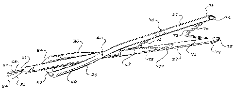
[0013] FIG. 1 is a perspective view of a first hemostatic clipping device
in the
closed position with two clips disposed therein.
[0014] FIG. 2 is the clipping device of FIG. 1 in the open position.
[0015] FIG. 3 is a perspective view of the clipping device of FIG. 1 in the
closed position.
[0016] FIG. 4 is the view of FIG. 3 with the clipping device in the open
position.
[0017] FIG. 5 is a perspective view of a hemostatic clipping device in the
closed position.
[0018] FIG. 6 is the device of FIG. 5 in the open position.
[0019] FIG. 7 is a side view of clip usable with the device of FIG. 1 in
the
closed position.
[0020] FIG. 8 is the clip of FIG. 7 in the open position shown
schematically
proximate to tissue to be closed with the clip.
[0021] FIG. 9 is the view of FIG. 8 with the clip in the closed position
and
closing the tissue.
[0022] FIGs. 10-15 are front views of detail A of FIG. 1 showing various
configurations of the distal end of the first and second arms and the distal
end of
the first and second fingers.
[0023] FIG. 16 is a perspective view of another hemostatic clipping device
in
the closed position.
[0024] FIG. 17 is the clipping device of FIG. 16 in the open position.
DETAILED DESCRIPTION OF THE DRAWINGS AND THE PREFERRED
EMBODIMENTS
[0025] Turning now to FIGs. 1-4, a first representative embodiment of a
hemostasis clip applicator device 10 is provided. The device includes a pair
of
4
CA 02760416 2011-10-28
WO 2010/126751
PCT/US2010/031845
first and second arms 20, 30 that are pinned together and pivot with respect
to
each other with a scissor-like mechanism. The first and second arms 20, 30
receive one or more hemostasis clips 70 therebetween, which may be expelled
from the device 10 to mechanically close an open wound in a patient's GI tract
or
in another similar area of the patient, such as a human or a mammal. A cannula
60 extends rearwardly from the first and second arms 20, 30 and may extend
remotely from the arms to define the proximal end of the device 10. The
cannula
60 receives a stylet or rod 66 therethrough, which may be moved within the
cannula 60, to urge the distal most clip 70 out of the device 10 when the clip
70 is
applied to the patient's tissue, and advance the next clip within the device
10 to a
position proximate the distal ends 22, 32 of the first and second arms 20, 30.
In
some embodiments, the stylet 66 may include markings upon the proximal end
portion thereof (i.e. the portion that extends out of the cannula 60) that are
spaced
at substantially the same distance apart as the length of the clips 70 (or
with
another suitable arrangement), to provide the user with a visual reference
guide
for precise application of one clip onto the patient at a time, and properly
positioning the next clip 70 for application onto the patient. In some
embodiments,
the cannula 60 may be formed by a tightly coiled coilspring, which defines a
lumen
therein. The cannula 60 may be about 230 cm to provide sufficient length for
placement into the desired locations within the GI tract that are
conventionally
reachable endoscopicly. The cannula 60 may include an outer low friction
coating
thereon, such as PET, PEBAX, TEFLON , PEEK, Nylon, or the like to minimize
friction associated with insertion of the device 10 into the patient.
[0026] The first arm 20 is an elongate member that includes a distal end
portion 22 and a proximal end portion 24 with a pinned connection
therebetween.
The first arm 20 is pivotally connected to a second arm 30 with a pinned or
similar
connection 40 that aligns and allows relative pivoting of the two arms 20, 30
with
respect to each other. The pinned connection 40 may be with a single pin that
extends through apertures in both the first and second arms 20, 30 (and the
cannula 60). In other embodiments, the pinned connection may be formed with
two pins that are substantially collinear with each other and independently
connected to opposite sides of the cannula 60. The use of two pins allows for
the
CA 02760416 2011-10-28
WO 2010/126751
PCT/US2010/031845
pivotable pinned connection 40 between the first and second arms 20, 30 (i.e.
each arm is pinned to the stationary cannula 60) while maintaining the lumen
within the cannula 60 open for passage of the stylet 66 therethrough.
[0027] The second arm 30 is constructed similarly to the first arm 20 and
similarly includes a distal end portion 32 and a proximal end portion 34 with
the
pinned connection 40 therebetween. The outer geometry of each of the first and
second arms 20, 30, are substantially semi-circular such that the outer
surface of
the first and second arms 20, 30 forms a substantially circular cross-section
along
the length the device 10 when the first and second arms 20, 30 are aligned in
the
closed position (FIGS. 1, 3), as discussed below. In some embodiments, the
device 10 is configured to fit within and be translated along a 2.8 mm
endoscope
channel. In other embodiments, the device is configured to travel within
differing
sized lumens, such as 3.2 mm and other commonly used endoscope channels.
Alternatively, the device 10 may be sized and configured to be inserted
through
the lumens of flexible sheaths or catheters in addition to or instead of an
endoscope.
[0028] The distal end portion 22, 32 of each of the first and second arms
20,
30 includes a track 28 defined blindly along the length of the distal end
portion 22,
32 from the distal end thereof through at least a portion of the length of the
distal
end portion 22, 32 of the respective arm 20, 30. The track 28 is of a length
sufficient to receive pins 78 extending from the number of clips 70 intended
to be
disposed within the device 10. Specifically, as discussed in detail below,
one, two,
or more clips 70 may be disposed between the distal portions 22, 32 of the
first
and second arms 20, 30 with pins 78 extending from the clips 70 being slidably
received within the track 28 in the respective arm. For example, for devices
intended to carry two clips 70, the track 28 must be at least slightly longer
than the
length of a first clip 70, and a portion distal end of the second (rearwardly
installed) clip 70 between the distal tip and the outwardly extending pin 78,
such
that the pins 78 from each clip 70 disposed between the arms 20, 30 are
slidably
received within the track. In other embodiments where the device is configured
to
retain three or more clips 70, the track 28 must be at least slightly longer
than two
6
CA 02760416 2011-10-28
WO 2010/126751
PCT/US2010/031845
clips (i.e. the track 28 must be slightly longer than the combined length of
one clip
less than the number of clips 70 to be positioned within the device 10).
[0029] The track 28 may be a slit that is defined through the entire wall
thickness of the arm (FIG. 10) or an alternate track 28 may be defined through
only a portion of the wall thickness of the arm (FIG. 13) to provided for arms
20,
30 with added strength. The track 28 may include parallel side walls, curved
side
walls, or may define a keyway 28a (FIGS. 11, 14, 15).
[0030] The proximal end portion 24, 34 of each of the first and second
arms
20, 30, and the pinned connection 40 of each arm, surrounds a cannula, or tube
60 that extends rearwardly beyond the first and second arms 20, 30. The
cannula
60 is an elongate member that provides a lumen for communication with and
operation of the arms 20, 30 to allow the device 10 to be remotely operated
when
inserted through and out of the endoscope within a patient. The cannula 60
provides a lumen for travel of an elongate stylet that extends through the
cannula
60and selectively engages the proximal end portion 71 of the rearmost clip 70
disposed between the first and second arms 20, 30. The stylet 66 may be urged
further into the cannula 60, which subsequently urges the distal most clip 70
out of
the device 10, to allow that clip 70 to remain within the patient and maintain
the
patient's tissue closed between the jaws 74, 75 of the clip 70, discussed
below.
[0031] The cannula 60 also may support and enclose two or more operational
wires 82, 84 that extend from the first and second arms 20, 30 and may be
manipulated by the physician to remotely transfer the device 10 from the first
closed position (FIG. 1) to the second, open position (FIG. 2). In some
embodiments, the wires 82, 84 are enclosed within the cannula 60 and extend
out
of the cannula 60 at the proximal end 64 thereof. The cannula 60 and wires 82,
84 may be engaged with a handle 90 and an operator 92 in an arrangement to
cause the wires to be selectively pulled in tension by the operator 92 to
create a
tensile force within the wires and accordingly pull the proximal ends of the
first and
second arms 20, 30 away from each other (and accordingly the distal ends 22,
32
of the arms to similarly pivot away from each other) by virtue of the scissors-
like
pinned connection 40.
7
CA 02760416 2011-10-28
WO 2010/126751
PCT/US2010/031845
[0032] In other embodiments, the wires 82, 84 may be pressed in
compression within the cannula 60 by the operator 92 that is slid forwardly
within a
track 93, which causes the proximal ends 24, 34 of the arms 20, 30 (and
therefore
the distal ends 22, 32 of the arms on the opposite side of the pivot point 40)
to
extend away from each other against the inward biasing force of the clips 70.
Due
to the continuous inward biasing force of the clips 70, the user must hold the
operator 92 in the active position (e.g. the forward position within track 93
as
shown in FIG. 6) to maintain the clip 70 and arms 20, 30 open during the
hemostasis clipping procedure.
[0033] In some embodiments, the first and second wires 82, 84 are connected
to separate and dedicated operators 92 such that the first and second arms 20,
30
(and therefore the respective finger 72, 73 connected to the respective arm)
can
be independently pivoted while the other of the first and second arm 20, 30
remains stationary. The dedicated operator may be similar to operator 92, with
the two dedicated operators disposed on opposite sides of the handle 90,
proximate to each other such that the user's thumb or finger engaging the
operator can comfortably manipulate both operators simultaneously, or a single
operator at a time.
[0034] The wires 82, 84 may be connected to the proximal ends of the arms
20, 30 by forming a loop (see FIG. 1) that extends through an aperture in the
respective arm, or using other known structures to fix the arms 20, 30 within
the
wires. The wires 82, 84 may be made from thinly drawn stainless steel,
Nitinol, or
another metal strong enough to carry the required compressive (or tensile
force)
but not contribute significantly to the overall size, weight, and cost of the
device.
In some embodiments, the wires 82, 84 are made from a material that is stiff
enough to avoid buckling or bending when the wires are pushed to rotate the
arms
20, 30 away from each other. In some embodiments, the cannula 60 defines one
or more wire lumens that support and direct the wires from the handle 90 to
the
arms 20, 30 and includes an inner cross-section similar to the outer cross-
section
of the wires to prevent the wires from buckling or bending therewithin when
placed
under a compressive load. The arms 20, 30 are configured to rotate toward each
other when force placed thereon by the wires 82, 84 (ultimately from the
operator
8 ,
CA 02760416 2011-10-28
WO 2010/126751
PCT/US2010/031845
92) is released. The clips 70 slidably disposed between the distal end
portions 23,
32 of the first and second arms 20, 30 are biased toward a closed position
(FIGs.
1, 7, and 9), and the closing biasing force of the clips 70 urge the arms
toward
each other when the force thereon from the wires (and operator 92) is
released.
[0035] In other embodiments, the first and second arms 20, 30 may be
remotely rotated with force transmission mechanisms other than elongate wires
82, 84. For example, in some embodiments, the distal end portion 67 of the
stylet
66 (or cannula 60 if relative motion is possible between the cannula 60 and
the
arms 20, 30) may have a plurality of gear teeth (such as rack teeth) that
engage
complimentary teeth (such as pinion teeth) disposed upon the first and second
arms 20, 30 such that longitudinal motion of the stylet 66 (or cannula 60)
causes
rotation of the arms 20, 30. Other known force transmission structures are
contemplated to allow for remote pivoting of the arms 20, 30.
[0036] One or more clips 70 may be provided between the distal end portions
of the first and second arms 20, 30 with the clips 70 arranged in a series
relationship such that the proximal end of the outer-most clip 70 (i.e. the
clip 70
that is first released from the arms 20, 30 with distal movement of the stylet
66
(discussed below)) is disposed proximate or contacting the distal end of the
next
clip 70 disposed within the device 10. As shown in FIGs. 7-9, the clips 70
include
first and second fingers 72, 73 that are fixed or connected together at the
proximal
ends 71 thereof. In some embodiments, the first and second fingers 72, 73 may
be monolithically formed together with the two fingers 72, 73 worked, bent, or
otherwise transferred to the final shape of the clip 70. In other embodiments,
the
first and second fingers 72, 73 may be two separate members attached together
with a joint at a proximal end, such as a pinned joint, a weld joint, with
adhesive,
mechanical fasteners, and the like.
[0037] The first and second fingers 72, 73 may be biased toward each other,
i.e. the first and second fingers 72, 73 are biased together such that the
distal
portions thereof, and specifically the jaws 74, 75 of the respective first and
second
fingers 72, 73 are biased to normally engage each other (or maintain close
proximity with each other). In some embodiments, the inward biasing force of
the
first and second fingers 72, 73 of the clips 70 are biased together with a
biasing
9
CA 02760416 2011-10-28
WO 2010/126751
PCT/US2010/031845
force established as the material forming the first and second fingers 72, 73
is
worked into the orientation where the first and second fingers 72, 73 are
aligned
substantially parallel with each other. The first and second fingers 72, 73
may be
configured to be biased together to provide a compressive force between the
first
and second jaws 74, 75 when the jaws engage, which assists in tightly holding
tissue therebetween. In embodiments where the first and second fingers 72, 73
are pinned or otherwise fixed together, the first and second fingers 72, 73
may be
biased together with a spring (such as a helical spring). 71b (FIG. 9)
disposed in
concert with the proximal end connection therebetween. The first and second
fingers 72, 73 are configured to be expandable to an open configuration (FIGs.
2,
8) with the pivoting of the first and second arms 20, 30 (due to engagement
between the pins 78 and the track 28 to allow the jaws 74, 75 to disengage to
be
aligned with the patient's tissue (T, S, R, FIGs. 8-9) to be closed via the
clip 70.
As discussed in detail below, when the jaws of the clip 70 are properly
aligned
with the desired tissue T, S, R to be closed, the outward force upon the first
and
second fingers 72, 73 is released (by allowing the arms 20, 30 to return to
the
closed position when the operator 92 is released) and the clip 70 returns to
the
normal closed position, with the jaws 74, 75 of the clip 70 engaging the
desired
tissue T, S, R (FIG. 9).
[0038] As shown in
FIGs. 10-15, the jaws 74, 75 of the respective first and
second fingers 72, 73 may be configured with several patterns or shapes, and
may be configured such that the first and second jaws 74, 75 engage when the
clip 70 is in the normal engaged position (FIGs. 1, 7, 9). For the sake of
understanding, FIGs. 10-15 depict the jaws 74, 75 in close proximity in the
closed
position. One of skill in the art will understand that the jaws 74, 75
depicted in
FIGs. 10-15 may be configured to normally contact each other when in the
closed
position.
[0039] As shown in
FIG. 10, the first and second jaws 74, 75 may include a
one or more ridges 76 and valleys 77 disposed thereon, which form teeth upon
the
jaws. The ridges 76 and valleys 77 may be substantially the same size and
shape
as the ridges 76 and valleys 77 disposed upon the opposite jaw and may be
disposed in opposite locations upon the opposite jaws, such that the ridges 76
on
CA 02760416 2011-10-28
WO 2010/126751
PCT/US2010/031845
a first jaw 74 are aligned in registry with the valleys 77 on the second jaw
75, and
the ridges 76 on the second jaw 75 are aligned in registry with the valleys 77
on
the first jaw 74 when the clip 70 is in the normal position. In other
embodiments
shown in FIG. 14, the ridges 76 and valleys 77 on opposite jaws 74, 75 may be
disposed in registry with each other, such that the tips of the 74 contact
each other
(or are aligned in close proximity to each other), when the clip 70 is in the
normal
position.
[0040] In still other embodiments, the jaws 74, 75 may have a plurality
of
different shapes, such as flat surfaces (FIG. 11), oppositely stepped surfaces
76e,
77e either in registry (FIG. 13) or out of registry, or arcuate surfaces 76b,
77b
either in registry (FIG. 12) or out of registry. In some embodiments, the
first and
second jaws 74, 75 may have two or more ridges 76 and valleys 77 thereon that
may be in registry (i.e. the ridges 76 on one jaw align with the valley s77 on
the
opposite jaw, shown in FIG. 15) or not in registry.
[0041] As discussed above and shown in FIGs. 10-15, each of the first and
second fingers 72, 73 includes a pin 78 that extends radially outward from the
outer surface of each pin. In some embodiments, the pin 78 is disposed
proximate the distal end of the respective finger 72, 73, and proximate to the
jaw
74, 75 on each finger. The pin 78 is configured to be received within the
track 28
defined within the distal end portion 22, 32 of the respective first and
second arm
20, 30. In some embodiments, the pin 78 may be a cylindrical member with an
enlarged head portion 78a (FIG. 10), with cylindrical body portion configured
to
extend between the walls of the respective arm that defines the track 28 and
the
head portion disposed in contact with outer surface of the arm, to retain the
pin 78
engaged with the track 28 against the inward biasing force of the clip 70. In
some
embodiments, the head portion may be cubic or boxlike (FIG. 10), spherical
(FIG.
12, 78d), disc-shaped, elliptical, or formed in any shape with a diameter
large
enough to retain the pin 78 within the track 28 against the biasing force of
the clip
70.
[0042] In other embodiments shown in FIGS. 11, 14, and 15, the pin 78 may
be (or include) a key 78c where the sides thereof are nonparallel and are
configured to ride within a similarly sized keyway 28b defining the track 28a
within
11
CA 02760416 2011-10-28
WO 2010/126751
PCT/US2010/031845
the respective arm. In some embodiments shown in FIGs. 13-15, the track 28 is
defined only partially through the wall of the arm, the pin 78 is sized with a
head
configured to slide within an open volume within the track 78 to maintain the
sliding connection between the two against the inward biasing force of the
clip 70.
In some embodiments shown in FIG. 15, the distal end portions 22, 32 of the
first
and second arms 20, 30 (and potentially the entire length of the first and
second
arms 20, 30) are formed with a width substantially equal to the width of the
first
and second fingers 72, 73 (and jaws 74, 75) of the clip 70 to minimize the
overall
width and size of the device 10 that is inserted through the lumen of the
endoscope and into the patient for use.
[0043] In some embodiments, the clip 70 may be formed from Nitinol or
various alloys thereof to take advantage of the superelastic properties of
Nitinol.
In some embodiments, the clip 70 may be formed from alloys of Nitinol that
exhibit
radiopaque properties, such as alloys with about 3 to about 14 percent
palladium,
or other radiopaque elements. The clips 70 may be formed in various shapes and
sizes, but generally the opposed fingers 72, 73 are substantially parallel
when the
fingers are in the relaxed position (FIGs. 7, 9). The clips 70 may be
approximately
0.5 inches long with the first and second fingers 72, 73 configured to be
expandable to form an opening of about 11 mm between the opposed jaws 74, 75
when in the open position (FIG. 8). As understood, the clips 78 (and other
portions of the device 10) may be constructed in different shapes and sizes
for
other uses within the patient. The clips 70 are configured to be strong enough
to
be openable and closable a plurality of times during operation of the device
10,
while maintaining the biasing force to the closed position after multiple
cycles of
the clip 70.
[0044] Turning now to FIGs. 16-17, another representative embodiment of a
hemostatic clipping device 200 is provided. The device 200 includes many of
the
same components as discussed with respect to the device 10, above, and for the
sake of brevity similar components are discussed with like element numbers.
The
device 200 includes first and second arms 220, 230 that are pivotably attached
at
pivot point 40, a cannula 60 that extends between a proximal portion of the
first
and second arms 220, 230 and further extends proximally of the arms for a
large
12
CA 02760416 2011-10-28
WO 2010/126751
PCT/US2010/031845
distance, such as 230 cm. The cannula 60 is configured to receive a stylet or
rod
66 therethrough to aid in the positioning and removal of clips 70 disposed
between
the first and second arms 220, 230.
[0045] The first arm 220 is an elongate member that includes a distal end
portion 222 and a proximal end portion 224. The first arm 220 is pivotally
connected to a second arm 230 with a pinned or similar connection 40 that
aligns
and allows relative pivoting of the two arms 220, 230 with respect to each
other.
The first and second arms 220, 230 are pivotably connected together with the
pivot point 40 disposed proximate the proximal end of each arm 220, 230, such
that the arms form a "V" shape when the arms are pivoted to the open position
(FIG. 17). The pinned connection 40 may be with a single pin that extends
through apertures in both the first and second arms 220, 230 (and the cannula
60). In other embodiments, the pinned connection 40 may be formed with two
pins that are substantially collinear with each other and independently
connected
to opposite sides of the cannula 60. The use of two pins allows for the
pivotable
connection between the first and second arms 220, 230 (i.e. each arm is pinned
to
the stationary cannula 60) while maintaining the lumen within the cannula 60
open
for passage of the stylet 66 therethrough.
[0046] The second arm 230 is constructed similar to the first arm 220 and
similarly includes a distal end portion 232 and a proximal end portion 234.
The
outer geometry of each of the first and second arms 220, 230 may be
substantially
semi-circular such that outer surface of the first and second arms 220, 230
collectively forms a substantially circular cross-section along the length the
device
200 when the first and second arms 220, 230 are aligned in the closed position
(FIG. 16), as discussed below. In some embodiments, the device 200 is
configured to fit within and be translated along a 2.8 mm endoscope channel.
In
other embodiments, the device is configured to travel within differing sized
lumens, such as 3.2 mm and other commonly used endoscope channels.
Alternatively, the device 200 may be sized and configured to be inserted
through
flexible sheaths or catheters rather than or in addition to an endoscope
[0047] The distal end portion of each of the first and second arms 220, 230
include a track 28 (shown as an internal keyway 28a in FIGs. 16-17, but may be
13
CA 02760416 2011-10-28
WO 2010/126751
PCT/US2010/031845
similar to other tracks 28 discussed above and depicted in FIGS. 10-15). The
track 28 that is defined blindly along the length of the respective arm 220,
230
from the distal end thereof and is of a length sufficient to receive pins 78
extending
from the number of clips 70 that are intended to be disposed within the device
10.
As with the device 10, the tracks 28 are configured to receive one, two, or
more
clips 70 between the first and second arms 220, 230. The track 28 is
configured
to receive clips 70 with the various size and shape pins 78 and jaws 74, 75
that
are discussed in the embodiments above.
[0048] The first and second arms 220, 230 are remotely openable with an
operator (see FIGs. 5, 6, elements 92, 93) that is movably connected to a
handle
90 (FIGS. 5-6), which is provided at the proximal end of the cannula 60 such
that
the operator 92 is manipulable when the device 200 is inserted within the
patient
(and the endoscope) and disposed proximate tissue to be closed with the clips
70.
Similar to the device 10, the operator 92 selectively pivots the first and
second
arms 220, 230 away from each other with the aid of wires 82, 84 (or other
force
transmission mechanisms discussed above) that are disposed therebetween. The
wires 82, 84 may connect with the first and second arms 220, 230 forward of
the
pivot point 40 therebetween, such that pulling the wires in tension (due to
movement of the operator 92 with respect to the handle 90) causes the first
and
second arms 220, 230 to pivot away from each other, and therefore open the
fingers 72, 73 (and jaws) of the clip 70 (FIG. 17). In other embodiments, the
wires
and the first and second arms 220, 230 may be configured such that pushing the
wires in compression may urge outward pivoting of the arms 220, 230. Because
the fingers of the one or more clips 70 connected to the first and second arms
220, 230 are biased toward the closed position, the clips 70 urge the first
and
second arms 220, 230 to pivot toward each other when the force in the wires is
released. The wires 82, 84 may be threaded through a lumen of the cannula
60between the proximal ends of the first and second arms 220, 230 and the
operator 92, and in some embodiments, the cannula 60 may include a dedicated
wire lumen to protect and enclose the wires.
[0049] The device 200 includes a stylet 66 that may be movably inserted
within the cannula 60 to urge the outermost clip from the device 200 when that
clip
14
CA 02760416 2011-10-28
WO 2010/126751
PCT/US2010/031845
engages tissue to be closed, with the removal of the outermost clip 70
aligning the
next clip 70 for action upon neighboring tissue and removal with repeated
operation of the arms 220, 230 via the operator 92.
[0050] In use, the hemostasis clip applicator device 10 (or device 200) may
be
loaded with one or a plurality of clips 70 (normally two or three) by
threading the
pins 78 extending from each of the first and second fingers 72, 73 of the clip
70
into a track 28 defined in the respective first and second arm 20, 30 of the
device
(or first and second arm 220, 230 of the device 200). Other than the location
of
the position of the pivot point 40 of the first and second arms of the devices
10
and 200 and the different connection point between the wires and the first and
second arms in the devices 10 and 200 (resulting in potentially different
operation
of the wires 82, 84 and operator 92 for the different embodiments), the device
10
and device 200 are generally constructed and operate in the same way.
Accordingly, the operation and use of either device is consistent with the
description of the device 10 here, with any exceptions for device 200
specifically
noted here.
[0051] Clips 70 are installed between the first and second arms 20, 30 of
device 10 in series such that the proximal end of the outer-most clip 70
contacts or
is proximate to the distal end of the neighboring clip 70. After the clips 70
are
inserted into the device 10, the device 10 is inserted into position within a
patient
(e.g. the GI tract) by being threaded through the working lumen of a
previously
positioned endoscope. The device 10 is urged into position by pushing the
cannula 60 which similarly moves the first and second arms 20, 30 and the
clips
70 disposed therebetween. While the device 10 is being positioned within the
endoscope and patient, the operator 92 is maintained in the normal position,
to
avoid the first and second arms 20, 30 from pivoting with respect to each
other,
which would block further motion within the endoscope, and potentially damage
the device 10, the endoscope or damage the patient's tissue, further
complicating
the procedure. In some embodiments, the cannula 60 may include markings upon
the outer surface corresponding to the length of the cannula 60 inserted into
the
endoscope.
CA 02760416 2011-10-28
WO 2010/126751
PCT/US2010/031845
[0052] When the device 10 is fully inserted into the patient, the first and
second arms 20, 30 are positioned outside of the endoscope lumen by urging the
cannula 60 further within the endoscope, to allow the first and second arms
20, 30
to be outwardly pivoted, as well as to provide a view of the device 10 and the
patient's tissue surrounding the endoscope by way of the camera or other
remote
vision system provided with the endoscope. The device 10 and the endoscope
are then manipulated by the physician to align the distal ends 22, 32 of the
first
and second arms 20, 30 with the tissue (T, S, R, FIGs. 8-9) to be closed with
the
hemostatic clips 70.
[0053] When properly positioned, the physician moves the operator 92
disposed upon the handle 90 to pivot the first and second arms 20, 30 away
from
each other and similarly open the clips 70 disposed therebetween the same
distance, which allows the tissue (T, S, R) to be positioned within the space
between the jaws 74, 75 upon the clip 70 (as shown in FIG. 8). The operator 92
is
then released, allowing the jaws 74, 75 to engage the selected tissue (T, S,
R)
therebetween due to the inward biasing force of the clips 70 (i.e. the
outermost
clip engaging the tissue and any clips 70 positioned within the device 10).
Upon
the clip closing and the jaws 74, 75 engaging the patient's tissue (T, S, R)
the clip
70 is released from between the first and second arms 20, 30 by slowly
withdrawing the cannula 60 from the endoscope, while maintaining the stylet 66
fixed. The relative motion between cannula 60 and stylet 66 causes the distal
end
67 of the stylet 66 to advance within the arms 20, 30 and push the proximal
end of
the proximal most clip 70 between the arms 20, 30. The proximal most clip 70
accordingly pushes its neighboring clip 70, until the distal most clip 70 is
slid
through the track 28 and out of the device 10. The relative motion of the
stylet 66
and cannula 60 is maintained for approximately the length of the clip 70, as
monitored by a plurality of length markings 69 provided upon the stylet 66 (or
cannula 60) and/or by viewing the device 10 and clip 70 through the
endoscope's
camera, or by a remote indication means such as ultrasound, x-ray, fluoroscopy
and the like. When the clip 70 is released from the device 10, the device 10
may
be repositioned to allow the next clip 70 between the first and second arms
20, 30
to engage further tissue to be closed by the clips 70. Alternatively, if the
16
CA 02760416 2011-10-28
WO 2010/126751
PCT/US2010/031845
procedure is complete (or the all clips within the device have been released),
the
device 10 is removed from the patient by withdrawing both the cannula 60 and
stylet 66 from the endoscope. The device 10 may be loaded with further clips
70
as necessary to continue the procedure, and the device 10 reinserted within
the
patient through the endoscope.
[0054] While the preferred embodiments of the disclosure have been
described, it should be understood that the disclosure is not so limited and
modifications may be made without departing from the disclosure. The scope of
the invention is defined by the appended claims, and all devices that come
within
the meaning of the claims, either literally or by equivalence, are intended to
be
embraced therein.
17