Note : Les descriptions sont présentées dans la langue officielle dans laquelle elles ont été soumises.
CA 02767228 2013-09-27
54106-1030
SAFETY BEARING FOR RETAINING A ROTOR SHAFT OF A MACHINE
FIELD
[0001] The invention relates to a safety bearing for retaining a
rotor shaft of a
machine.
BACKGROUND
[0002] Magnetic bearings are increasingly used nowadays for mounting
rotating rotor shafts of machines during operation, said magnetic bearings
maintaining the rotating rotor shaft in a floating state with the aid of
magnetic fields. In
the event that the magnetic bearing fails, e.g. as the result of a power
failure, the
rotor shaft falls into a safety bearing and is retained thereby. A safety
bearing
therefore serves to retain the rotor shaft. The safety bearing temporarily
takes over as
the mounting of the rotor shaft until the rotor shaft is at a complete
standstill. Safety
bearings must firstly withstand the shock when the rotating rotor shaft falls
into the
safety bearing and, secondly, ensure safe running down of the rotor shaft in
the
safety bearing. For this purpose, the safety bearing has a slightly larger
internal
diameter compared with the rotor shaft diameter so that, during normal
operation,
that is, with the magnetic bearing active, the rotor shaft does not touch the
safety
bearing. Usually, the safety bearing is accommodated in the machine carcass in
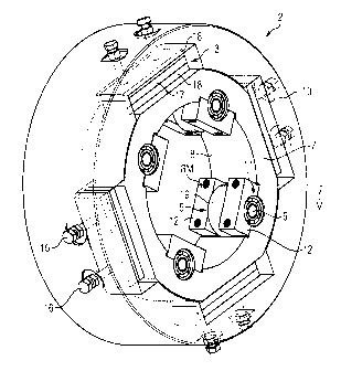
the
region of the respective end of the rotor shaft.
[0003] Safety bearings must firstly withstand the shock when the rotating
rotor
shaft falls into the safety bearing and, secondly, ensure safe running down of
the
rotor shaft in the safety bearing. For this purpose, certain frictional
characteristics and
kinematic conditions must be met. Excessively high friction between the
sliding or
rolling components would lead within a very short time to severe heating and
thus to
a short service life of the safety bearing. This has the result that running
down of the
rotor shaft in the safety bearings without braking is not possible in most
cases.
Therefore, for the safe operation of machines in which the rotor shaft is
mounted with
1
CA 02767228 2013-09-27
54106-1030
magnetic bearings, braking devices must generally be provided for decelerating
the
rotor shaft.
la
CA 02767228 2012-01-04
W02011/003759
PCT/EP2010/059117
[0004] If
a magnetic bearing fails, the rotor shaft falls, as stated above, into the
safety bearing. The danger exists herein that the rotor shaft performs a
"backward
whirl", rolling along the inner surface of the safety bearing. By contrast to
rotationally
synchronous rotor motion wherein the rotor deflection takes place
synchronously with
the circulating imbalance excitation, in the case of a backward whirl, the
rotor shaft
performs the orbit in the reverse direction to the rotor shaft rotation with a
very large
amplitude. A portion that is rotationally synchronous and has a much smaller
amplitude is overlaid, so that an elliptical orbit is produced.
[0005] The
conditions for the occurrence of a backward whirl are manifold. The
occurrence of backward whirl generally leads, due to the very large forces
involved,
to disruption or damage of the machine.
[0006] The
use of roller bearings as safety bearings is known from the prior
art. The outer ring of a roller bearing is connected to the bearing end plate.
The inner
diameter of the inner ring of the safety bearing is somewhat larger than the
outer
diameter of the rotor shaft. During a crash, the rotor shaft falls into the
inner ring so
that the inner ring and the rolling bodies are accelerated after a very short
time and
the rotor shaft runs down. A safety bearing based on a roller bearing is,
firstly,
unsuitable for large rotor weights and, secondly, the danger of backward whirl
exists.
[0007]
Furthermore, the use of dry sliding bearings as safety bearings is
known. The rotor shaft falls directly into a fixed ring which comprises
individual
coated bearing shells, and runs down there. Given unfavorable frictional
characteristics, the rotor shaft is able to enter into backward whirl.
[0008]
Previously, attempts were made, using complex proofs based on
calculations and experiments, to show that backward whirl does not occur in
the
aforementioned known safety bearings, taking account of all the known
framework
conditions. This type of procedure is time-consuming and costly.
2
CA 02767228 2013-09-27
54106-1030
SUMMARY
[0009] It is an object of some embodiments of the invention to
provide a safety
bearing in which the probability of backward whirl occurring is greatly
reduced
compared with safety bearings from the prior art.
[0010] According to one aspect of the present invention, there is provided,
a
safety bearing for retaining a rotor shaft of a machine, the safety bearing
having a
first carrier body rotating about a virtual geometrical central axis (M), and
rolling
bodies, the rolling bodies each having a region which is arranged between the
central
axis (M) and the first carrier body, the rolling bodies each being rotatably
connected
to the first carrier body via a shaft; wherein the safety bearing has a second
carrier
body arranged round the first carrier body, elastic elements being arranged
between
the first carrier body and the second carrier body; wherein the elastic
elements each
comprise a layer of rubber and two lawyers of metal, the layer of rubber being
arranged between the two layers of metal.
[0011]
[0012] It has proved to be advantageous, in some embodiments if the
rolling
bodies are configured as rollers. Rollers are a common configuration of the
rolling
bodies and are particularly easy and economical to manufacture.
[0013] It has also proved to be advantageous, in some embodiments if
the first
carrier body is configured as a ring, since a ring has a form that is
particularly
mechanically stable.
[0014] It has also proved to be advantageous, in some embodiments if
the
rolling bodies are arranged evenly distributed round the periphery of the
first carrier
body, since a backward whirl can then be particularly reliably prevented.
[0015] It has also proved to be advantageous, in some embodiments if the
rolling bodies are each rotatably connected via a shaft and at least one
roller bearing
to the first carrier body, since then a particularly low coefficient of
friction is achieved.
3
CA 02767228 2013-09-27
541 06-1 030
[0016] It has also proved to be advantageous, in some embodiments if
the
safety bearing has a second carrier body arranged round the first carrier
body, elastic
elements being arranged between the first carrier body and the second carrier
body.
By this means, the shock loading acting on the rolling bodies and the roller
bearings
in the event of a crash of the rotor shaft into the safety bearing is reduced.
[0017] It has also proved to be advantageous, in some embodiments if
the
second carrier body is configured as a ring, since a ring has a mechanically
particularly stable form.
[0018] It has also proved to be advantageous, in some embodiments if
the
elastic elements are configured as spring damping elements or as damping
elements.
The configurations of the elastic elements given above are common
configurations of
the elastic elements.
[0019] It has also proved to be advantageous, in some embodiments if
the
elastic elements are arranged, relative to the virtual geometrical central
axis, radially
aligned with the rolling bodies.
[0020] It has also provided to be advantageous, in some embodiments
if the
elastic elements are arranged offset in a tangential direction from the
rolling bodies.
This provides a particularly simple overall arrangement.
[0021] It has also proved to be advantageous, in some embodiments to
configure a machine with safety bearings according to the invention. Here, the
machine preferably has a magnetic bearing for operational mounting of the
rotor
shaft.
[0022] It has also proved to be advantageous, in some embodiments to
configure a machine having the safety bearing according to the invention. The
machine preferably has a magnetic bearing for operational mounting of the
rotor
shaft. The machine can be configured, for example, as an electric motor or a
4
CA 02767228 2013-09-27
54106-1030
generator or a compressor or a condenser or as a turbine. The machine can
particularly be configured as a wind power generator.
BRIEF DESCRIPTION OF THE DRAWINGS
[0023] Two exemplary embodiments of the invention are illustrated in
the
drawings and will now be described in greater detail, making reference to the
drawings, in which:
[0024] FIG 1 is a schematic representation of a machine which has a
safety
bearing according to the invention,
[0025] FIG 2 is a perspective representation of the safety bearing
according to
the invention in the context of a first embodiment of the invention, and
[0026] FIG 3 is a perspective representation of the safety bearing
according to
the invention in the context of a second embodiment of the invention.
DETAILED DESCRIPTION
[0027] FIG 1 shows, in the form of a schematic representation, the
elements of
a machine 1 that are essential to an understanding of the invention,
configured, in the
context of the exemplary embodiment, as an electric motor. Other elements of
the
machine, such as the rotor yoke, that are not essential to an understanding of
the
invention are not shown in FIG 1 for the sake of clarity. The machine 1 has a
rotatable rotor shaft 3 mounted with a magnetic bearing 4, said shaft
rotating, during
operation of the machine, about a virtual geometrical rotation axis R.
[0028] A magnetic bearing 4 holds the rotor shaft 1 suspended with a
regulated magnetic field in an air gap 15. For this purpose, the magnetic
bearing 4
has coils as essential elements for generating the magnetic field.
[0029] Aside from the magnetic bearing 4, the machine 1 comprises a
safety
bearing 2 which retains the rotor shaft 1 in the event of a failure of the
magnetic
bearing 4, when said shaft falls into the safety bearing 2, which then takes
over the
5
CA 02767228 2013-09-27
54106-1030
mounting of the rotor shaft 3 until the rotor shaft 3 comes to a standstill.
Such a
failure of the magnetic bearing 4 can occur, for example, if the current to
the machine
1, and therefore to the magnetic bearing 4, fails. It should be noted at this
point that
the safety bearing 2 and the magnetic bearing 4 are shown purely symbolically
in the
schematic sectional view in FIG 1, in the form of rectangles.
[0030] The machine 1 also has a stationary machine housing 14 to
which the
safety bearing 2 is fastened, wherein the fastening between the safety bearing
2 and
the machine housing 14 is not shown in FIG 1 for the sake of clarity.
[0031] Arranged between the safety bearing 2 and the rotor shaft 3 is
an
airgap 9. With the magnetic bearing 4 switched on and functioning correctly,
the
safety bearing 2 has no contact with the rotor shaft 3. In the event of a
failure of the
magnetic bearing 4, for example, as the result of a power failure, the rotor
shaft 3 falls
into the safety bearing and mechanical contact takes place between the rolling
bodies
of the safety bearing according to the invention (see FIG 2 and FIG 3) and the
rotor
shaft 3 rotating in particular, rapidly rotating, during operation of the
machine 1.
[0032] FIG 2 shows the safety bearing according to the invention in
the form of
a perspective, partially transparent, representation of a first embodiment of
the
invention.
[0033] The safety bearing 2 according to the invention has a first
carrier body 7
and rolling bodies surrounding a virtual geometric central axis M, wherein,
for clarity,
only one rolling body 5 is provided with a reference sign. The central axis M
extends
through the geometric centre GM of the first carrier body 7. In the first
exemplary
embodiment, the first carrier body 7 is configured as a ring. However, the
first carrier
body can also have a different geometrical form about the central axis M, for
example, a square form. The rolling bodies have a region 19 which is arranged
between the central axis M and the first carrier body 7. In this exemplary
embodiment, the individual rolling bodies are firmly connected to an
associated,
preferably rod-shaped shaft (mechanical axle), wherein for the sake of
clarity, only
one shaft 6 is provided with a reference sign. The shaft 6 preferably is
connected,
6
CA 02767228 2013-09-27
541 06-1 030
rotatable via roller bearings 11, to the interior side 8 of the first carrier
body 7. The
roller bearings 11 are arranged at both ends of the shaft 6 and fixed by means
of
holding devices 12 to the interior side 8 of the first carrier body 7. In the
exemplary
embodiment, therefore, the interior side 8 of the first carrier body 7 is
provided with
recesses. The individual rolling bodies are therefore each rotatably connected
via an
associated shaft to the first carrier body 7. It should be noted at this point
that
alternatively, the individual rolling bodies can also be rotatably connected
via
respectively assigned, preferably rod-shaped shafts, to the first carrier body
7 in that
the respective shaft is firmly connected to the first carrier body 7 and the
respective
rolling body is rotatably connected, e.g. via a roller bearing, to the shaft.
The rolling
bodies are arranged evenly distributed round the periphery of the first
carrier body.
The rolling bodies are therefore arranged evenly spaced round the periphery of
the
first carrier body.
[0034] In the context of the exemplary embodiment, the rolling bodies
are
configured as rollers.
[0035] If the rotor shaft 3 falls into the safety bearing 2, said
shaft comes into
contact with the exterior surface of the rolling bodies, so that the rolling
bodies
immediately begin to rotate. The invention prevents the occurrence of backward
whirl
by minimizing the frictional surfaces on which the rotor shaft 3 can roll
during running
down in the safety bearing 2. The rolling bodies have only a very small
frictional area
which comes into contact with the rotor shaft 3. Therefore only very little
friction
occurs between the safety bearing and the rotor shaft. In an advantageous
embodiment of the invention, the friction is further minimized by the use of
roller
bearings in which the shafts are mounted. The rotor shaft 3 rolls over the
exterior
surface of the rolling bodies. As a result of the very low friction between
the safety
bearing and the rotor shaft achieved with the invention, the occurrence of
backward
whirl is reliably prevented.
[0036] The safety bearing according to the invention also preferably
comprises
a second carrier body 10 arranged round the first carrier body 7. In the
exemplary
7
CA 02767228 2013-09-27
54106-1030
embodiment, the second carrier body 10 is configured as a ring. The second
carrier
body can, however, also have a different geometrical form, such as a square
form.
Arranged between the first carrier body 7 and the second carrier body 10 in
the
exemplary embodiment are elastic elements and, for the sake of clarity, only
one
elastic element 13 is provided with a reference sign. The elastic elements
comprise
one layer 17 of rubber and two layers 18 of metal, the layer 17 of rubber
being
arranged between the two layers of metal 18.
[0037] As a result of the elastic elements, the shock acting on the
rolling
bodies during impacting of the rotor shaft is effectively absorbed, thereby
protecting
the rolling bodies and the roller bearings.
[0038] In the exemplary embodiment of FIG 2, the elastic elements are
arranged offset in the tangential direction relative to the rolling bodies,
which enables
an overall arrangement which is structurally easy to realize. In the exemplary
embodiment of FIG 2, the elastic elements are arranged offset relative to the
virtual
geometric central axis M extending through the geometric center GM of the
first
carrier body 7 by an angle of 45 to the rolling bodies.
[0039] FIG 3 shows a second embodiment of the invention. The basic
construction of this embodiment essentially corresponds to that of FIG 2
described
above. The same elements are therefore shown in FIG 3 with the same reference
8
CA 02767228 2012-01-04
W02011/003759
PCT/EP2010/059117
signs as in FIG 2. The essential difference relative to the embodiment of FIG
2 lies
therein that in the embodiment of FIG 3, the elastic elements are arranged
radially
aligned with the rolling bodies relative to the virtual geometrical central
axis M of the
first carrier body 7. The individual rolling bodies are therefore arranged in
a line with
the respective associated elastic elements. This embodiment has the advantage
that
the force acting upon the rolling bodies during impact by the rotor shaft can
be
particularly effectively absorbed, since the force generated by the shock is
directly
conducted in the radial direction into the elastic elements and therefore, for
example,
the rolling bodies and the roller bearings are particularly well protected and
the
loading thereon is particularly greatly reduced.
[0040] In
the embodiment of FIG 3, two elastic elements are assigned to each
rolling body. The number of elastic elements that are used per rolling body
and their
configuration can be adapted to the loads impinging upon the rolling bodies
and the
roller bearings used for mounting the rolling bodies.
[0041] As
shown in FIG 2 and FIG 3, the elastic elements are fastened with
screws to the second carrier body 10, wherein, for the sake of clarity, only
two
screws 16 are identified with reference signs. It should be noted here that
the elastic
elements are preferably pre-tensioned in order to increase their damping
effect.
[0042] The
elastic elements must not necessarily be evenly distributed round
the periphery of the first carrier body, as in the exemplary embodiment.
Furthermore,
the elastic elements can be arranged round the periphery of the first carrier
body
arbitrarily in relation to the rolling bodies.
[0043]
Furthermore, the rolling bodies also do not necessarily have to be
arranged evenly distributed round the periphery of the first carrier body, as
in the
exemplary embodiment.
9
CA 02767228 2012-01-04
WO 2011/003759
PCT/EP2010/059117
[0044] It
should also be noted at this point that, of course, more than two roller
bearings per rolling body can be provided for mounting the rolling body.
[0045] It
should also be noted that the safety bearing according to the
invention should preferably comprise at least two rolling bodies, although
naturally
the safety bearing can comprise more than the four rolling bodies selected for
the
exemplary embodiments of FIG 2 and FIG 3.
[0046] The
safety bearing according to the invention prevents, to a high
degree of probability, the occurrence of backward whirl. Said safety bearing
is
suitable both for high rotary speeds and also for high rotor shaft weights.
The safety
bearing also has a small space requirement.