Note : Les descriptions sont présentées dans la langue officielle dans laquelle elles ont été soumises.
CA 02769838 2012-02-01
WO 2010/143222 PCT/IT2010/000325
TITLE :
"SUPPORT COLLAR FOR LONG ARTICLES, IN
PARTICULAR CABLES, PIPES AND/OR THE LIKE"
DESCRIPTION
The present invention relates to a support collar for long articles, in
particular cables, pipes and/or the like.
The subject of the present invention is suitable for use in the
telecommunications and building sector and, in particular, is
intended to support cables, pipes and/or similar articles with a long
shape.
As is known, the supporting of cables or pipes is usually performed
with the aid of a plurality of support collars which can be rapidly
fixed onto corresponding support structures normally consisting of
special plates with holes.
The aforementioned support collars generally have relatively elastic
structures which are formed by means of respective open profiles.
According to these configurations, the support collars may be
splayed elastically so that they can be rapidly fitted onto the pipes or
tubes to be supported.
The document US 6,161,804 describes and illustrates a support
collar which has a sheet-like structure provided with a curved
portion intended to engage with the cable or pipe to be supported.
Two plate-like portions terminating in respective engaging elements
extend laterally from the curved portion.
The plate-like portions and the curved portion delimit a respective
1
CA 02769838 2012-02-01
WO 2010/143222 PCT/IT2010/000325
area for housing the cable or pipe to be supported, which is suitably
fixed in a stable position by two or more retaining lugs which extend
from the said plate-like portions.
The engaging elements are designed to be inserted inside a
respective hole formed through the support plate of a respective
support structure. Once the engaging elements have been inserted
inside the respective hole, the engaging elements remain locked in
this position by respective contact surfaces which engage with the
support plate on the opposite side to the curved portion. The
disengagement of the collar from the support plate requires firstly
the movement of the engaging elements towards each other and then
extraction thereof through the respective hole in the support plate.
According to a further example described and illustrated in the
document US 6,354,543, the support collar has a flat top end portion
is which has a hole in the centre. The central hole allows engagement
and fastening of another support collar in positions on top of each
other, while the flat surface of the top end portion provides a stable
resting surface for the mounted support collar.
In this case also, engagement of one support collar on another one is
able to be performed by means of insertion of respective engaging
elements which hook onto the corresponding top end portion through
the central hole, while disengagement is performed by moving the
engaging elements towards each other until they can be extracted
through the central hole of the respective top end portion.
Also known are collars which are formed in the manner of a clip and
2
CA 02769838 2012-02-01
WO 2010/143222 PCT/IT2010/000325
can be deformed elastically so as to fix cables or pipes to respective
support structures.
In particular, these collars comprise a substantially flat engaging
portion which is screwed directly to the support structure and fixed
onto the latter by means of at least one locking screw. Two side
portions extend from the flat portion and delimit a narrow
intermediate space suitable for receiving the cable or pipe to be
supported. The side portions can be splayed elastically so as to
allow the introduction of the cable or pipe inside the intermediate
to space. Retention of the cable or pipe to be supported is performed by
the side portions of the support collar which press transversely the
respective article to be supported.
Despite the fact that the aforementioned support collars are able to
support long articles, such a cables, pipes and/or the like, the
Applicant has found that, however, they are not without a number of
drawbacks and that various aspects may be improved, mainly in
connection with the stability of the articles supported, the flexibility
of use of the support collars with respect to the different cross-
sections and/or cross-sectional forms of the cables or pipes to be
supported, the elasticity of the side walls and, consequently, the
adaptability thereof to cables or pipes with large cross-sections, the
practicality of application of the support collars on cables or pipes,
the simplicity of installation thereof, the positioning thereof along
the cables or pipes to be supported, the amount of material required
for manufacture thereof, as well as the costs for manufacture and/or
3
CA 02769838 2012-02-01
WO 2010/143222 PCT/IT2010/000325
marketing thereof.
In particular, as regards the support collars which can be engaged on
the support plates or other collars by means of corresponding
engaging elements, the Applicant has found that the plate-like side
portions of the latter are excessively rigid. The rigidity of the plate-
like side portions is due to their configuration in the form of a hump
or with curved sections, necessary for housing cables or pipes with a
circular cross-section.
In addition, the plate-like side portions are provided with respective
structural folds which define the undulating profile thereof,
rigidifying significantly the structure.
The excessive structural rigidity limits substantially the capacity of
the known collars to adapt to the different forms and dimensions of
the cables or pipes to be supported. Therefore, each support collar
may be applied only on cables or pipes which have transverse
dimensions corresponding to the transverse dimensions of the
housing area intended for them.
It must also be mentioned that the manufacture of a structure
provided with a series of curved portions requires, on the one hand,
the implementation of complex method and, on the other hand, the
use of a significant quantity of material which increases substantially
both the overall production costs and the costs for marketing of these
support collars.
With reference instead to the collars formed in the manner of a clip
these have the drawback that they have an open side through which
4
CA 02769838 2012-02-01
WO 2010/143222 PCT/IT2010/000325
accidental extraction of the mounted cable or pipe may occur. In
greater detail, since it has an open form, the clip is unable to retain
the mounted cable or pipe in the event of accidental separation from
the side portions of the collar. In other words, when the mounted
cable accidentally disengages from the side portions of the collar, it
separates completely from it, with dangerous consequences.
The object of the present invention is to propose a support collar for
long articles, in particular cables, pipes and/or like, able to solve the
problems encountered in the prior art.
to In particular, one object of the present invention is to propose
stackable support collars which ensure stable fixing in position of
cables or pipes.
A further object of the present invention is to propose a stackable
support collar which is able to adapt to the different forms and cross-
sections of cables or pipes to be supported.
An object of the present invention is to propose a support collar of
the stackable type, the structure of which can be deformed elastically
depending on the article to be supported.
An object of the present invention is to simplify the method for
manufacturing support collars.
A further object of the invention is to reduce the costs for production
and marketing of the support collars.
Yet another object of the present invention is to provide a support
collar of the stackable type which can be easily applied to the cables
or pipes to be supported.
5
CA 02769838 2012-02-01
WO 2010/143222 PCT/IT2010/000325
A further object of the invention is to propose a support collar which
can be easily installed.
Finally an object of the invention is to provide a support collar of the
stackable type which is simple to position along the longitudinal
extension of the cables or pipes to be supported.
The objects mentioned, together with others, are substantially
achieved by a support collar for long articles, in particular cables,
pipes and/or the like, in accordance with that expressed in the
accompanying claims.
The description of a preferred, but not exclusive embodiment of a
support collar for long articles, in particular cables, pipes and/or the
like, is now provided by way of example, where:
Figure 1 is a perspective view of a support collar for long
articles, which is partly' splayed, in accordance with the present
invention;
Figure 2 is a front view of the support collar according to the
preceding figure:
Figure 3 is a side view of the support collar according to the
preceding figures;
Figure 4 is a perspective view of the support collar according
to the preceding figures, shown in the customary configuration, i.e.
not splayed;
Figure 5 shows a front view of the support collar according to
Figure 4;
Figure 6 is a side view of the support collar according to
6
CA 02769838 2012-02-01
WO 2010/143222 PCT/IT2010/000325
Figures 4 and 5;
Figure 7 is a plan view of the planar extension of the support
collar according to the preceding figures;
Figure 8 shows an elevation view of the planar extension of
the support collar according to Figure 7;
Figure 9 is a front schematic view of the support collar
according to the preceding figures engaged on a support plate;
Figure 10 is a front schematic view of two support collars
during stacking;
Figure 11 is a front schematic view of the two support collars
according to Figure 10, stacked on top of each other;
Figure 12 is a side view of the stacked support collars
according to Figure 11.
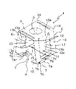
With reference to the accompanying figures, 1 denotes in its entirety
a support collar for long articles, in particular cables, pipes and/or
the like in accordance with the present invention.
As can be seen in the accompanying figures, the support collar 1
comprises a substantially sheet-like structure 2 formed by means of
shearing and folding of a corresponding plate 3 (Figures 7 and 8),
preferably made of steel.
It is possible, however, for the support collar 1 according to the
present invention to be made, for example by means moulding of a
plastic material, which is preferably flexible, elastic and resistant.
The sheet-like structure 2 comprises a substantially flat top-end
portion 4 which has, preferably, in a central position, at least one
7
CA 02769838 2012-02-01
WO 2010/143222 PCT/IT2010/000325
through-opening 5.
According to the embodiment shown in the accompanying figures,
the opening 5 in the top end portion 4 has a circular shape which is
delimited by a structural depression in the top end portion 4.
However, it must be mentioned that the form of the opening 5 in the
top end portion 4 does not limit in any way the invention, operation
of which is effective also with openings 5 which have a shape
different from that shown, for example, a rectangular shape, square
shape, elliptical shape and the like.
Still with reference to the accompanying figures. two side portions 6
extend laterally from the top end portion 4 and each terminate in a
respective engaging element 7.
Advantageously, the side portions 6 extend substantially
perpendicularly with respect to the top end portion 4, with a
substantially planar extension, so as to define an open profile which
is substantially square-shaped and preferably substantially
rectangular and even more preferably in the form of an overturned
U.
Obviously, the embodiment of the side portions 6 shown in the
figures and described in detail does not limit in any way the present
invention which may envisage support collars 1 provided with side
portions 6 directed obliquely with respect to the top end portion, or
side portions 6 which are curved with the concavity directed towards
the housing area 9 or outwards.
In particular, each side portion 6 does not have intermediate folds in
8
CA 02769838 2012-02-01
WO 2010/143222 PCT/IT2010/000325
order to provide the sheet-like structure 2 of the support collar I with
sufficient elasticity in the directions transverse to the side portions
6. In this way the sheet-like structure 2 is free to flex in relation to
the stresses which may arise.
The purpose of the aforementioned engaging elements 7 is to ensure,
on the opposite side to the top end portion 4, joining of the support
collar 1 to a support plate 8 (Figure 8) or to any other support
structure (not shown) or to a top end portion 4 of another support
collar 1 in a stacked and superimposed arrangement.
io With reference to Figures 1, 2, 4, 5 and 9 to 12, the side portions 6
and the top end portion 4 of each support collar 1 delimit an area 9
for partially housing a long article 10 (Figures 10 and 11) to be
supported, such as, for example, an electric cable, ducting, a pipe, a
bar or any other object with a long form.
Advantageously the support collar 1 comprises retaining means 11
operating within the housing area 9 so as to keep the long article 10
in a stable position.
Preferably, the retaining means I1 comprise at least one retaining
clip 12 provided with two gripping arms 13 which extend inside the
housing area 9.
The gripping arms 13 can be deformed elastically so as to receive in
engagement, inside the housing area 9, the respective long article 10
to be supported.
In detail, the gripping arms 13 can be splayed elastically so as to
9
CA 02769838 2012-02-01
WO 2010/143222 PCT/IT2010/000325
retain the long article 10, exerting transversely on the latter a
pressure sufficient to keep it in a stable position.
Advantageously each gripping arm 13 of the retaining clip 12 is
formed from the structure of a respective side portion 6 of the
support collar 1.
As can be seen in Figures 1, 2, 4, 5 and 9 to 12, each gripping arm
13 extends inside the housing area 9 from a respective edge 14.
In accordance with the embodiment shown in Figures 1, 2, 4, 5 and 9
to 12, each gripping arm 13 extends from a respective edge 14
io situated between the top end portion 4 and a corresponding side
portion 6.
It must be pointed out, however, that operation of the retaining clip
12 is not dependent in any way on the embodiment shown and that it
may be designed such that the gripping arms 13 forming the gripping
clip 12 extend from corresponding edges arranged on the opposite
side to the top end portion 4, in the region of the respective engaging
elements 7.
In addition, it is also possible for the gripping arms 13 which form
the retaining clip 12 to extend inside the housing area 9 directly from
the side portions 6 or from the top end portion 4 adjacent to the
opening 5 in the latter.
With particular reference to the structure of the retaining clip 12,
each gripping arm 13 has a first substantially flat segment 13a
extending from a respective edge 14 of the sheet-like structure 2 of
CA 02769838 2012-02-01
WO 2010/143222 PCT/IT2010/000325
the support collar I towards the centre of the housing area 9. A
second segment l3b also extends from the first segment 13a, said
segment being curved and preferably with its concavity directed
towards the centre of the housing area 9 in order to provide a
suitable surface for supporting the outer surface of the long article 10
to be supported. On the opposite side to the first segment 13a, a
third substantially flat segment 13c extends from the second segment
13b away from the centre of the housing area 9 so as to define a
receiving portion for insertion and engagement of the long article 10
o to be supported.
Advantageously, as can be seen from the accompanying figures, the
function, performed by the retaining clip 12, of retaining the long
article 10 is independent of and not conditioned by the function,
performed by the support collar 1, of engagement with the support
plate 8 or with another support collar 1. In other words, the retaining
clip 12 ensures engagement of the support collar 1 with the
corresponding long article 10 independently of engagement of the
support collar 1 with another support collar 1 or with a suitable
support structure. In this way, during installation and/or preparation
of all the elements needed for installation of the cable or pipe, the
operators may mount the support collars 1 on the structure of the
long article 10 to be fixed, joining them together stably without
having yet fixed the support collars onto the support plate 8.
According to a further advantageous aspect of the present invention,
11
CA 02769838 2012-02-01
WO 2010/143222 PCT/IT2010/000325
the retaining clip 12 of each support collar 1 transversely constrains
the long article 10 to the respective support collar 1, leaving them
free to slide longitudinally with respect to each other. More
particularly, once the support collar 1 has been mounted on the long
article 10 to be supported, the support collar 1 may slide thereon so
as to be positioned along the longitudinal extension of the article 10
according to the installation requirements, thereby facilitating
considerably said installation work.
Still with reference to the accompanying figures, the engaging
Io element 7 of each side portion 6 of the support collar 1 extends from.
a respective locating surface 15 which extends substantially parallel
to the top end portion 4 with a substantially flat extension so as to
ensure stable mounting of the support collar 1 on the support plate 8
or on a top end portion 4 of another support collar 1. Each locating
surface 15 can therefore be arranged against a corresponding surface
of the support plate 8 or top end portion 4 of another support collar
1.
With particular reference to the engaging elements 7, each of them
comprises at least one plate 7a projecting transversely, preferably
perpendicularly, from the corresponding locating surface 15 on the
opposite side to the top end portion 4. Each engaging element 7 also
comprises at least one pair of wedge-like elements 7b arranged on
the sides of the corresponding plate 7a. Each wedge-like element 7b
has advantageously an insertion surface 7c inclined relative to the
12
CA 02769838 2012-02-01
WO 2010/143222 PCT/IT2010/000325
corresponding plate 7a and the locating surface 15, so as to facilitate
introduction of the plate 7a through a corresponding through-
opening (not shown) formed in the support plate 8 or through the
opening 5 in the top end portion 4 of another support collar 1.
Advantageously, each wedge-like element 7b also has a contact
surface 7d substantially perpendicular to the respective plate 7a and
substantially parallel to the corresponding locating surface 15 so as
to remain in contact against a respective locating surface of the
support plate 8 or the top end portion 4 of another support collar 1.
io The support collar 1 in accordance with the present invention solves
the problems encountered in the prior art and achieves important
advantages.
Firstly, the arrangement of the retaining clip 12 inside the housing
area 9 of the sheet-like structure 2 means that engagement of the
support collar 1 with the respective cable or pipe to be supported is
not conditioned by engagement of the support collar with the support
plate 8 or with another support collar 1. Basically, joining of the
support collar 1 to the cable or to the pipe to be supported may be
performed independently of fixing of the support collar 1 to any
support structure. In this way, during preparation of the installation
work, the support collars 1 may be easily fitted on the cable or the
pipe to be supported without performing permanent fixing thereof,
said operation being able to be performed subsequently by simply
force-fitting the engaging elements 7 inside the through-openings in
13
CA 02769838 2012-02-01
WO 2010/143222 PCT/IT2010/000325
the support plate 8 or the through-openings 5 in the top end portions
4 of other support collars 1.
It must also be considered that the constraining action provided by
the retaining clip 12 of each support collar 1 joins the respective
support collar to the pipe or cable to be supported only transversely
with respect to its longitudinal extension, leaving it free to slide
thereon. This characteristic feature is particularly advantageous
during the installation operations where longitudinal sliding of the
support collars 1 on the cable or pipe to be supported allows rapid
alignment of the engaging elements 7 with the respective through-
openings in the support structure to be used.
It must also be considered that the presence of side portions without
structural folds imparts a greater degree of elasticity to the sheet-like
structure 2. In this way the support collar can be easily adapted to
different forms and/or sizes of the cables or pipes to be supported. In
particular, the support collar according to the present invention is
suitable for supporting both collars having a cross-section which
may vary from rounded (circular or elliptical) profiles to square-
shaped (rectangular or square) profiles and thicknesses varying from
narrow to wide cross-sections.
It must also be considered that the elimination of the folds from the
side portions results in a significant saving in the amount of material
used for manufacture of the support collars, with a corresponding
reduction in the overall costs for production and marketing thereof.
14