Note : Les descriptions sont présentées dans la langue officielle dans laquelle elles ont été soumises.
CA 02773096 2012-03-02
WO 2011/028592 PCT/US2010/046765
ILLUMINATION DEVICE FOR USE IN AN OPHTHALMIC SURGICAL APPARATUS
FIELD OF INVENTION
The present invention relates to illumination devices for ophthalmic
surgery and methods of use thereof.
BACKGROUND OF THE INVENTION
The need to provide illumination to facilitate performance of ophthalmic
surgery in a patient's eye is known. To efficiently and reliably provide such
illumination has been difficult, particularly for vitreoretinal surgery. A
significant
factor in efficient and reliable illumination is coupling of light from a
source
disposed in a surgical console into a fiber optic of an illumination device.
The
fiber optic acts as a conduit to deliver the light to a surgical handpiece and
into
patients' eyes.
In addition to the need of coupling light into the fiber is a need to
appropriately dissipate heat generated in the fiber optic when the fiber is
exposed
to the intense light provided by the source. To date, the problems of coupling
light into a fiber and dissipating heat have been addressed by providing a
metallic heat sink proximate the end of the fiber and using the heat sink as a
connector to the console. In such a configuration, the heat sink is inserted
into a
port in the console and retained by friction between the heat sink and the
console.
1
CA 02773096 2012-03-02
WO 2011/028592 PCT/US2010/046765
SUMMARY
Aspects of the present invention are directed to techniques for enhancing
alignment of an end of a fiber optic within an ophthalmic surgical console to
provide better coupling of light from a source into the end of the fiber.
Other
aspects of the invention are directed to a fiber optic connector providing
shutter
control to control light escaping the console into a surgery room. Yet other
aspects of the invention are directed to ensuring proper connection of an
illumination device to a surgical console.
An illumination device, according to the exemplary embodiment, is for use
in an ophthalmic surgical apparatus. The illumination device includes a fiber
optic
having a proximal end and a connector coupled to the fiber optic. The
connector
has a datum surface disposed a predetermined distance from the proximal end.
The connector is configured and arranged to connect with the surgical
apparatus
such that the datum surface positions the proximal end at a predetermined
location within the surgical apparatus when the connector is connected to the
surgical apparatus.
In one example the connector also includes a heat sink surrounding a
portion of the fiber optic. The heat sink is also attached to the connector
wherein
the fiber optic proximal end is located proximate an end of the heat sink.
In another example the connector is adapted to fit into and move a collar
within a port in the surgical apparatus upon insertion of the connector into
the
port, thereby opening a shutter within the surgical apparatus to transmit
light
through the fiber optic.
2
CA 02773096 2012-03-02
WO 2011/028592 PCT/US2010/046765
In still another example the connector includes a visual indicator disposed
a predetermined distance from the proximal end such that a position of the
visual
indicator provides a visual indication that the connector is fully inserted
into the
surgical apparatus.
A method of coupling an illumination device to an ophthalmic surgical
apparatus comprising a light source is also accomplished by providing a fiber
optic having a proximal end, providing a connector with a datum surface
coupled
to the fiber optic; and coupling the connector to the surgical apparatus such
that
the proximal end is positioned at a predetermined location relative to the
light
source by interference of the datum surface with a surface of the surgical
apparatus, thereby transmitting light from the light source into the proximal
end
and through the fiber optic.
Some examples also include a connector coupled to the fiber optic where
the connector has a shutter actuation surface configured and arranged to open
a
shutter in the surgical apparatus when the connector is being connected to the
surgical apparatus and to maintain the shutter in an open position when the
connector is coupled to the surgical apparatus such that light from the light
source is transmitted into the proximal end and through the fiber optic.
BRIEF DESCRIPTION OF THE DRAWINGS
Illustrative, non-limiting embodiments of the present invention will be
described by way of example with reference to the accompanying drawings, in
which the same reference number is used to designate the same or similar
components in different figures, and in which:
3
CA 02773096 2012-03-02
WO 2011/028592 PCT/US2010/046765
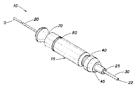
FIG. 1 A is a schematic illustration of an example of an illumination device
for use in an ophthalmic surgical apparatus according to aspects of the
present
invention;
FIG. 1 B is a schematic cross-sectional illustration of an example of an
illumination device for use in an ophthalmic surgical apparatus according to
aspects of the present invention;
FIG. 2 is a schematic, partial cross-sectional illustration of an example of
an ophthalmic console including a port for connecting an illumination device;
and
FIG. 3 is a schematic, partial cross-sectional illustration of an example of
an ophthalmic console including a port having an illumination device connected
thereto.
DETAILED DESCRIPTION
FIG. 1A is a schematic illustration of an example of an illumination device
for use in an ophthalmic surgical apparatus according to aspects of the
present invention, and FIG. 1 B is a schematic, cross-sectional illustration
of an
example of an illumination device 10 for use in an ophthalmic surgical
apparatus
according to aspects of the present invention. Aspects of the invention will
now
be described with reference to both FIGs. 1 A and 1 B.
Illumination device 10 comprises a fiber optic 20, a connector 15 and a
heat sink 30. It will be appreciated that an ophthalmic surgical handpiece
(not
shown) is provided on the distal end D of the illumination device from which
light
is projected into a patient's eye to permit observation by surgical staff,
during
surgery. The handpiece can have any suitable, known or yet to be developed
4
CA 02773096 2012-03-02
WO 2011/028592 PCT/US2010/046765
configuration. In embodiments having a heat sink 30 surrounding a portion of
the
fiber optic, the heat sink is also attached to the connector 15 so that the
fiber
optic proximal end 22 is located proximate an end of the heat sink 30.
Fiber optic 20 has a proximal end 22. The fiber optic is positioned with the
proximal end 22 exposed to light from a source (discussed below) which is
disposed within the surgical console such that light can be propagated through
the fiber to distal end D. It will be appreciated that proper and consistent
positioning of the proximal end 22 is desirable for efficient and reliable
illumination of a patient's eyes. In particular, it is desirable that such
positioning
be achieved when a used device 10 is removed and a new device 10 is
connected to a console numerous times.
To facilitate suitable positioning of the proximal end 22, according to
aspects of the present invention, fiber optic 20 is coupled to connector 15
which
comprises a datum surface 25 that is disposed a predetermined distance from
the proximal end 22. It will be appreciated that if fiber optic 20 is
maintained at a
fixed location within the connector, as discussed in greater detail below, by
interfacing datum surface with a datum surface within the console, the
positioning
of the proximal end in the z-direction can be achieved. It will also be
appreciated
that by maintaining fiber optic 20 in intimate contact with the connector the
positioning of the proximal end 22 in the x-direction and the y-direction can
also
be achieved. Accordingly, the connector 15 is configured and arranged to
connect with the ophthalmic surgical apparatus such that datum surface 25
positions proximal end 22 at a predetermined location within a surgical
apparatus
CA 02773096 2012-03-02
WO 2011/028592 PCT/US2010/046765
(e.g., within a console) when the connector is connected to the surgical
apparatus. It will be appreciated that it is typically advantageous that the
datum
surface 25 be located near the proximal end of connector 15 (i.e., relatively
near
the fiber proximal end 22) to reduce stack-up of tolerances which would limit
the
precision with which proximal end 22 can be positioned. In the illustrated
embodiment, datum surface 25 is illustrated as a simple vertical surface;
however, more complicated shapes can be used.
Connector 15 may be manufactured from any suitable rigid material.
Typically the material is a heat insulator to prevent transfer of heat
generated by
the fiber from reaching housing or an operator's hand. For example, the
connector may be made of an acetal homopolymer such as Delrin available
from the Dupont Corporation.
To facilitate control of light emitted from the console by the source the
connector 15 comprises a shutter actuation surface 45. Interaction of shutter
actuation surface 45 with a shutter in the surgical apparatus is discussed in
greater detail below. It will be appreciated that the shutter actuation
surface 45
causes the shutter to open, when connector 15 is being connected to the
surgical
apparatus. In addition, the shutter remains in an open position when the
connector 15 is coupled to the surgical apparatus such that light from the
light
source is transmitted into the proximal end 22 and through fiber optic 20.
Such
a configuration provides advantages over a gravity operated shutter, which
needs to be manually moved out of the way prior to insertion of the
illumination
device.
6
CA 02773096 2012-03-02
WO 2011/028592 PCT/US2010/046765
In some embodiments, the connector comprises a visual indicator 60
disposed a predetermined distance from the proximal end. The connector 15 is
configured and arranged to connect with the surgical apparatus such that the
visual indicator 60 position provides a visual indication that the connector
15 is
fully inserted into the surgical apparatus. In the illustrated embodiment,
when the
connector 15 is fully inserted, the visual indicator 60 is immediately
adjacent an
outer surface 62 of a housing of the surgical apparatus 64 (see FIG. 3). In
the
illustrated embodiment, the visual indicator 60 is represented by a groove. Of
course, visual indicator 60 may assume other forms, for example, a raised
ridge,
and/or a contrasting color, or other suitable visible feature.
The illumination device 10 may further comprise a heat sink 30 coupled to
fiber optic 20 at a location proximate the proximal end 22. In embodiments
where a heat sink is included, it is typically desirable to maintain the fiber
in
intimate contact with the heat sink to facilitate precise positioning of
proximal end
22 in the x-direction and the y-direction. That is heat sink 30 is typically a
relatively rigid metallic tube or needle that has a larger enough lumen to
allow
easy insertion of an optic fiber during manufacturing but where the lumen is
small
enough that the fiber proximal end 22 is able to be reliably located in the x
and y
directions within the tolerances of the design requirements. In embodiments
including a heat sink, it is also typically desirable to maintain the
connector in
intimate contact with the heat sink to further facilitate precise positioning
of the
proximal end.
7
CA 02773096 2012-03-02
WO 2011/028592 PCT/US2010/046765
It will be appreciated that an embodiment according to aspects of the
present invention can be provided with one or more of a datum surface, a
shutter
actuation surface and a visual indicator.
FIG. 2 is a schematic, partial cross-sectional illustration of an example of
an ophthalmic surgical console 100 including a port 110 for connecting
illumination device 10. FIG. 3 is a schematic, partial cross-sectional
illustration of
an example of an ophthalmic surgical console 100 including a port 110 having
illumination device 10 connected thereto. FIGs. 2 and 3 will be referenced
together when describing aspects of the present invention below.
Console 100 contains a light source S. The light source is positioned to
be capable of projecting light though port 110. The light source may comprise
any suitable light emitting apparatus (e.g., an incandescent lamp or an LED).
Console 100 may be an ophthalmic surgical system such as those known in the
art that contains apparatus in accordance with the present examples or console
100 could be a stand alone ophthalmic illuminator, similar to those known in
the
art, and incorporates apparatus in accordance with the present examples.
As described above with reference to FIG. 1 B, the illumination device 10
comprises a fiber optic 20 having a proximal end 22 through which light enters
illumination device 10, and a connector 15 coupled to the fiber optic 20. The
connector 15 is connected with the surgical console 100. The connector 15 is
configured and arranged such that datum surface 25 positions the proximal end
22 at a predetermined location relative to light source S. Typically, a pair
of
datum surfaces (e.g., one on a console and one on an illumination device)
8
CA 02773096 2012-03-02
WO 2011/028592 PCT/US2010/046765
achieves alignment. By this technique, mechanical positioning between a pair
of
datum surfaces can achieve and maintain alignment within a predetermined
operating range, depending on the requirements of the amount of light needed
to
be captured by fiber optic 20. For example, the datum surface 25 when abutting
surface 141 (see FIGs. 2 and 3) may operate to position proximal end 22 at a
location proximate a focal point of lens 150 or at another position to capture
a
particular amount of light from the source S.
In the illustrated embodiment, port 110 is moveable in direction V upon
insertion of an illumination device 10 into the port 110 to operate an
illumination
shutter 120. Illumination shutter 120 controls whether light is transmitted
through
port 110. The shutter has an open position in which the shutter permits light
to
be transmitted through the port, and a closed position (shutter 120 is shown
in
the closed position in FIG. 2) in which the shutter 120 blocks transmission of
light.
A biasing feature 146 biases the shutter in the closed position. Biasing
feature
146 in the present example is simply a spring arm that causes shutter 120 to
return to the closed position when illumination device 10 is removed; however,
biasing feature 146 may comprise any structure that ensures that shutter 120
blocks light when an illumination device 10 is not connected to console 100.
In the illustrated embodiment, a shutter actuation device 140 includes a
shutter collar 143 that slides within port 110. Shutter collar 143 is
connected to
an arm 130. Arm 130 has a tapered edge 144 that, when moved in direction V
as an illumination device 10 is inserted, forces the shutter 120 downward
(i.e.,
9
CA 02773096 2012-03-02
WO 2011/028592 PCT/US2010/046765
overcoming the biasing feature) via contact with structure 147, permitting
light L
to pass into proximal end 22.
Shutter actuation surface 45 is configured and arranged to open shutter
120 in the console when the connector 15 is being connected to the console. In
the illustrated embodiment, shutter actuation surface 45 is sized and shaped
to
interfere with surface 145 of shutter collar 143 in the port 110 such that,
upon
insertion of connector 15 into port 110, actuation device 140 opens shutter
120 in
the manner described above.
Shutter actuation surface 45 is configured to maintain the shutter in an
open position such that light from the light source S is transmitted into the
proximal end 22 and through the fiber 20 so long as connector 15 is connected
within port 110.
In some embodiments, one or more features may be present to provide
further retention of illumination device 10 beyond that which may be provided
by
friction between the connector 15 and the port 110. In the illustrated
embodiment,
region or groove 40 having a reduced diameter is provided on the connector 15
and a detent is provided on the surgical apparatus to maintain connector in
operative position during use. For example, in the illustrated embodiment, the
detent comprises a plunger 122 biased using a flexible bar 124 that is
attached to
the console by fasteners 126.
It may also be advantageous that surfaces of the connector 15 be beveled
to facilitate insertion of the connector 15 into port 110. In some
embodiments, it
is advantageous to provide features that facilitate removal of the connector
from
CA 02773096 2012-03-02
WO 2011/028592 PCT/US2010/046765
the port such as indent 70 shaped to permit a user's fingers to be inserted
therein
so as to reliably grasp the connector.
Having thus described the inventive concepts and a number of exemplary
embodiments, it will be apparent to those skilled in the art that the
invention may
be implemented in various ways, and that modifications and improvements will
readily occur to such persons. Thus, the embodiments are not intended to be
limiting and presented by way of example only. The invention is limited only
as
required by the following claims and equivalents thereto.
11