Note : Les descriptions sont présentées dans la langue officielle dans laquelle elles ont été soumises.
CA 02776487 2015-02-19
METHOD AND APPARATUS FOR GENERATING A THREE-
DIMENTIONAL SIMULATION GRID FOR A RESERVOIR MODEL
CROSS REFERENCE TO RELATED APPLICATION
[0001] This application claims the benefit of U.S. Provisional Patent
Application
61/260,589, filed November 12, 2009, entitled Method and Apparatus for
Reservoir
Modeling and Simulation.
FIELD
[0002] Aspects disclosed herein relate to a method and apparatus for
reservoir modeling
and/or reservoir simulation, particularly but not exclusively to a method and
apparatus for
generating a grid for a reservoir model.
BACKGROUND
[0003] This section is intended to introduce various aspects of the art,
which may be
associated with embodiments of the disclosed techniques. This discussion is
believed to assist
in providing a framework to facilitate a better understanding of particular
aspects of the
disclosed techniques. Accordingly, this section should be read in this light,
and not
necessarily as an admission of prior art.
[0004] Over the past few decades, numerous technological advances in the
oil industry
have increased the success rate of finding reserves, developing these and
improving the
hydrocarbon recovery from existing resources. In addition, advances in
computing
capabilities have enabled geologists and engineers to model the reservoirs
with increasing
accuracy. Various technologies have been developed to understand a prospective
reservoir by
providing geological and reservoir information at different scales varying
from a few inches
(for example in core plug analysis) to tens of meters horizontally and a few
meters vertically
(seismic imaging data).
[0005] Construction of reservoir models has become a crucial step in
resource
development as reservoir modeling allows the integration of all available data
in combination
with a geologic model. One of the challenges in reservoir modeling is accurate
representation
of reservoir geometry, including the structural framework which may include
major
depositional surfaces that are nearly horizontal (also known as horizons),
fault surfaces which
can have arbitrary spatial size and orientation, and detailed stratigraphic
layers. Figure 1
illustrates a complex reservoir geometry which contains multiple fault
surfaces which deviate
from the vertical direction.
- 1 -
CA 02776487 2012-04-02
WO 2011/059535 PCT/US2010/043462
[0006] A structural framework outlines the major components of the
reservoir and it is
often used to model the fluid volumes located in the reservoir and the fluid
movement during
production. It is therefore helpful for the structural framework to be modeled
accurately.
However, to date, modeling of structural frameworks for practical reservoir
modeling has
been hampered by difficulties in generating a suitable grid. Specific
challenges in generating
a grid for a structural framework arise from the complex structure of sub-
surface reservoir
geometries. The typical aspect ratio of reservoir dimensions (horizontal in
relation to vertical
dimensions) can be several orders of magnitude. As a consequence, the aspect
ratio of the
grid cells is usually between 10 and 100.
[0007] Prismatic or 2.5 D Voronoi grids, constructed by the projection or
extrusion of a
2D Voronoi grid in a vertical or near vertical direction, are widely accepted
for reservoir
simulations (see, for example, WO 2008/150325). The prismatic grid cells can
be easily
constrained to resolve horizons or stratigraphic layer boundaries. Voronoi
grids are much
more flexible and adaptive than structured corner point grids which are
commonly used in
reservoir simulators. Voronoi grids generally require fewer grid cells to
represent and
simulate the geometry in comparison to conventional corner point grids. This
reduces
computing power requirements whilst the accuracy of the models is not
compromised.
However, in complex reservoir geometries where fault surfaces deviate from the
vertical
plane, generating an accurate constrained grid still poses problems and as a
result, the
accuracy of reservoir models for complex reservoir geometries is still
compromised.
[0008] "Efficient and accurate reservoir modeling using adaptive gridding
with global
scale up", Branets et al., SPE 118946 (2009), discloses techniques for
generating an
adaptively constrained 2.5D Voronoi grid.
[0009] U.S. Patent No. 6,106,561 discloses a simulation gridding method and
apparatus
including a structured area gridder adapted for use by a reservoir simulator.
This disclosure is
concerned with generating a 2.5D structured grid based on segmented coordinate
lines.
Coordinate lines are vertical or near vertical lines which approximate the
fault surface
geometry. An areal 2D grid is projected along the coordinate lines to form a
2.5D prismatic
grid. This gridding method cannot cope with complex system of faults or highly-
deviated
(from vertical) faults, as this results in unacceptable grids with inside-out
cells and vertices
outside of the model domain. Also, structured grids generally require a lot of
computing
power for solving the reservoir model, and therefore, these grids are
unsuitable for the
simulation of large reservoirs comprising multiple structural faults.
- 2 -
CA 02776487 2012-04-02
WO 2011/059535 PCT/US2010/043462
[0010] "Challenges and technologies in reservoir modeling", Branets et al.,
Communications in Computational Physics, Volume 6, Number 1, pages 1-23,
discloses an
overview of the technology in reservoir modeling, grid generation, grid
adaptation and global
scale-up methods to date.
[0011] Aspects disclosed herein aim to obviate or at least mitigate the
above described
problems and/or to provide improvements generally.
SUMMARY
[0012] A method is provided as defined in any one of the accompanying
claims.
[0013] In particular, there is provided a method of generating a three-
dimensional
simulation grid for a reservoir model comprising: providing a geological model
comprising
horizons, constraints and multiple geological grid cells; constructing a pre-
image
corresponding to the geological grid cells, said pre-image comprising a
surface, said
modeling constraints being mapped onto said surface; generating a constrained
two-
dimensional grid on the pre-image, the two-dimensional grid comprising
multiple grid cells;
selecting simulation layer boundaries from said geological model and
projecting the
constrained two-dimensional grid onto said simulation layer boundaries;
generating prismatic
cells to form the three-dimensional simulation grid; and outputting the three-
dimensional
simulation grid.
[0014] The grid is thus effectively constructed from a pre-image containing
the
constraints from the geological model. This enables faults to be accurately
represented by the
grid.
[0015] According to aspects and methodologies, the pre-image may be
constructed by
selecting a parametric space corresponding to a base horizon. The parametric
space may
comprise multiple vertices. The vertices may be moved to correspond with the
location of the
constraints in the geological model. The constraints may be approximated in
the three-
dimensional space of a geological model and the constraints may be mapped onto
the pre-
image. The pre-image may be adjusted to match the constraints. Edges of the
pre-image grid
are matched to the corresponding constraints on the pre-image. The pre-image
may be
constructed by defining a continuous base horizon surface across one or more
faults,
smoothing the continuous base horizon, and projecting the continuous base
horizon onto a
plane to form the pre-image, the pre-image including multiple vertices. Fault
vertices of the
base horizon may be merged to locate the fault vertices on the continuous base
horizon. The
- 3 -
CA 02776487 2012-04-02
WO 2011/059535 PCT/US2010/043462
fault vertices on the continuous base horizon surface may be located
equidistant from the
fault intersections of the base horizon on either side of the fault. The
continuous base horizon
may be smoothed by moving one or more vertices in a k-direction of the
geological model.
The base horizon may be projected vertically onto the plane to form the pre-
image. The
constrained two-dimensional grid may be generated on the pre-image. The two-
dimensional
grid cells may include identifiers corresponding to the grid cells of the
geological model. The
grid cells may be projected along k direction lines of the geological grid
cells. The constraints
may include internal constraints and/or external constraints, the constraints
including
modeling constraints for simulation grid generation representing subsurface
reservoir
elements. The internal constraints may be included in the geological model.
The external
constraints may include modeling constraints ancillary to the geological
model.
Hydrocarbons in a hydrocarbon reservoir may be managed using the three-
dimensional
simulation grid.
[0016] In another embodiment, there is provided a simulation gridding
apparatus for
generating a grid for a reservoir model comprising the following features,
which may be
computer-based: a geological model comprising horizons, constraints and
multiple geological
grid cells; a pre-image corresponding to the geological grid cells, said pre-
image comprising
a surface, the modeling constraints being mapped onto the surface; a generator
for generating
a constrained two-dimensional grid on the pre-image, the two-dimensional grid
comprising
multiple grid cells; a selector for selecting simulation layer boundaries from
the geological
model and a projector for projecting the constrained two-dimensional grid onto
the simulation
layer boundaries; a generator for generating prismatic cells to form the three-
dimensional
simulation grid; a transferor for transferring reservoir properties to the
three-dimensional
simulation grid; a definer for defining state variables and/or state
parameters for each grid
cell in the three-dimensional simulation grid; and a solver for simulating
physical and
chemical processes related to hydrocarbon production on the three-dimensional
simulation
grid.
[0017] According to methodologies and techniques, the two-dimensional grid
cells may
include identifiers corresponding to the grid cells of the geological model.
The constraints
may include at least one of internal constraints and external constraints. The
internal
constraints may include modeling constraints for simulation grid generation
representing
subsurface reservoir elements. The external constraints may include modeling
constraints
ancillary to the reservoir.
- 4 -
CA 02776487 2012-04-02
WO 2011/059535 PCT/US2010/043462
[0018] A reservoir simulator is provided. The reservoir simulator includes
a gridding
apparatus having: a geological model comprising horizons, constraints and
multiple
geological grid cells; a pre-image corresponding to the geological grid cells,
the pre-image
comprising a surface, the modeling constraints being mapped onto the surface;
a generator for
generating a constrained two-dimensional grid on the pre-image, the two-
dimensional grid
comprising multiple grid cells; simulation layer boundaries selected from the
geological
model and a projector for projecting the constrained two-dimensional grid onto
said
simulation layer boundaries; and a generator for generating prismatic cells
from the two-
dimensional grid to form the three-dimensional simulation grid. The reservoir
simulator also
includes computer based transfer means for transferring reservoir properties
to the three-
dimensional simulation grid, and a solver for simulating physical and chemical
processes
related to hydrocarbon production on the three-dimensional simulation grid
based on state
variables and/or state parameters for each grid cell in the three-dimensional
simulation grid.
[0019] A program storage device is provided. The program storage device is
readable by
a machine and tangibly embodying a program of instructions executable by the
machine. The
instructions include: code for providing a geological model comprising
horizons, constraints
and multiple geological grid cells; code for constructing a pre-image
corresponding to the
geological grid cells, said pre-image comprising a surface, said modeling
constraints being
mapped onto said surface; code for generating a constrained two-dimensional
grid on the pre-
image, the two-dimensional grid comprising multiple grid cells; code for
selecting simulation
layer boundaries from said geological model and projecting the constrained two-
dimensional
grid onto said simulation layer boundaries; and code for generating prismatic
cells from the
two-dimensional grid to form the three-dimensional simulation grid.
BRIEF DESCRIPTION OF THE DRAWINGS
[0020] Disclosed aspects and their advantages will now be described in more
detail by
way of example only and with reference to the accompanying drawings in which
[0021] Figure 1 shows a diagrammatic view of a complex structural framework
of a
reservoir;
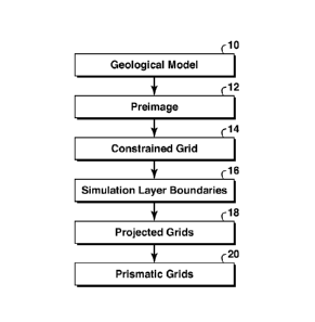
[0022] Figure 2 shows a diagrammatic flow chart of the method steps
according to
disclosed aspects;
[0023] Figures 3A-3C show a diagrammatic view of a base horizon, its
corresponding
parametric space, and its final pre-image;
- 5 -
CA 02776487 2015-02-19
[0024] Figures 4A and 4B show a pre-image modification;
[0025] Figures 5A and 5B show the simplification of original constraints
into simplified
constraints;
[0026] Figures 6A and 6B show the modification of an original pre-image by
coinciding
constraint edges of the parametric space with the simplified constraints of
the pre-image;
[0027] Figures 7A and 7B show a base horizon and its vertical projection or
pre-image;
[0028] Figures 8A and 8B show a smoothed pre-image surface and its vertical
projection
or pre-image;
[0029] Figures 9A-9E show the projection of a two-dimensional grid onto a
simulation
layer boundary;
[0030] Figure 10 is a block diagram illustrating a computer environment;
[0031] Figure 11 is a block diagram of machine-readable code;
[0032] Figure 12 is a side elevational view of a hydrocarbon management
activity; and
[0033] Figure 13 is a flowchart of a method of extracting hydrocarbons from
a subsurface
region.
DETAILED DESCRIPTION
[0034] To the extent the following description is specific to a particular
embodiment or a
particular use, this is intended to be illustrative only and is not to be
construed as limiting the
scope of the invention.
[0035] Some portions of the detailed description which follows are
presented in terms of
procedures, steps, logic blocks, processing and other symbolic representations
of operations
on data bits within a memory in a computing system or a computing device.
These
descriptions and representations are the means used by those skilled in the
data processing
arts to most effectively convey the substance of their work to others skilled
in the art. In this
detailed description, a procedure, step, logic block, process, or the like, is
conceived to be a
self-consistent sequence of steps or instructions leading to a desired result.
The steps are
those requiring physical manipulations of physical quantities. Usually,
although not
necessarily, these quantities take the form of electrical, magnetic, or
optical signals capable of
being stored, transferred, combined, compared, and otherwise manipulated. It
has proven
CA 02776487 2012-04-02
WO 2011/059535 PCT/US2010/043462
convenient at times, principally for reasons of common usage, to refer to
these signals as bits,
values, elements, symbols, characters, terms, numbers, or the like.
[0036] Unless specifically stated otherwise as apparent from the following
discussions,
terms such as "providing", "constructing", "generating", "selecting",
"projecting", "moving",
"calculating", "modeling", "transferring", "defining", "solving",
"simulating", "forming",
"performing", "mapping", "outputting", "approximating", "adjusting",
"matching",
"smoothing", "merging", "locating", "assigning", "managing", or the like, may
refer to the
action and processes of a computer system, or other electronic device, that
transforms data
represented as physical (electronic, magnetic, or optical) quantities within
some electrical
device's storage into other data similarly represented as physical quantities
within the
storage, or in transmission or display devices. These and similar terms are to
be associated
with the appropriate physical quantities and are merely convenient labels
applied to these
quantities.
[0037] Embodiments disclosed herein also relate to an apparatus for
performing the
operations herein. This apparatus may be specially constructed for the
required purposes, or
it may comprise a general-purpose computer selectively activated or
reconfigured by a
computer program or code stored in the computer. Such a computer program or
code may be
stored or encoded in a computer readable medium or implemented over some type
of
transmission medium. A computer-readable medium includes any medium or
mechanism for
storing or transmitting information in a form readable by a machine, such as a
computer
('machine' and 'computer' are used synonymously herein). As a non-limiting
example, a
computer-readable medium may include a computer-readable storage medium (e.g.,
read only
memory ("ROM"), random access memory ("RAM"), magnetic disk storage media,
optical
storage media, flash memory devices, etc.). A transmission medium may be
twisted wire
pairs, coaxial cable, optical fiber, or some other suitable transmission
medium, for
transmitting signals such as electrical, optical, acoustical or other form of
propagated signals
(e.g., carrier waves, infrared signals, digital signals, etc.).
[0038] Furthermore, modules, features, attributes, methodologies, and other
aspects can
be implemented as software, hardware, firmware or any combination thereof
Wherever a
component of the invention is implemented as software, the component can be
implemented
as a standalone program, as part of a larger program, as a plurality of
separate programs, as a
statically or dynamically linked library, as a kernel loadable module, as a
device driver,
and/or in every and any other way known now or in the future to those of skill
in the art of
- 7 -
CA 02776487 2012-04-02
WO 2011/059535 PCT/US2010/043462
computer programming. Additionally, the invention is not limited to
implementation in any
specific operating system or environment.
[0039] At the outset, and for ease of reference, certain terms used in this
application and
their meanings as used in this context are set forth. To the extent a term
used herein is not
defined below, it should be given the broadest definition persons in the
pertinent art have
given that term in at least one printed publication or issued patent.
[0040] As used herein, "displaying" includes a direct act that causes
displaying, as well
as any indirect act that facilitates displaying. Indirect acts include
providing software to an
end user, maintaining a website through which a user is enabled to affect a
display,
hyperlinking to such a website, or cooperating or partnering with an entity
who performs
such direct or indirect acts. Thus, a first party may operate alone or in
cooperation with a
third party vendor to enable the reference signal to be generated on a display
device. The
display device may include any device suitable for displaying the reference
image, such as
without limitation a CRT monitor, a LCD monitor, a plasma device, a flat panel
device, or
printer. The display device may include a device which has been calibrated
through the use
of any conventional software intended to be used in evaluating, correcting,
and/or improving
display results (e.g., a color monitor that has been adjusted using monitor
calibration
software). Rather than (or in addition to) displaying the reference image on a
display device,
a method, consistent with the invention, may include providing a reference
image to a
subject. "Providing a reference image" may include creating or distributing
the reference
image to the subject by physical, telephonic, or electronic delivery,
providing access over a
network to the reference, or creating or distributing software to the subject
configured to run
on the subject's workstation or computer including the reference image. In one
example, the
providing of the reference image could involve enabling the subject to obtain
the reference
image in hard copy form via a printer. For example, information, software,
and/or
instructions could be transmitted (e.g., electronically or physically via a
data storage device
or hard copy) and/or otherwise made available (e.g., via a network) in order
to facilitate the
subject using a printer to print a hard copy form of reference image. In such
an example, the
printer may be a printer which has been calibrated through the use of any
conventional
software intended to be used in evaluating, correcting, and/or improving
printing results (e.g.,
a color printer that has been adjusted using color correction software).
- 8 -
CA 02776487 2012-04-02
WO 2011/059535 PCT/US2010/043462
[0041] As used herein, "exemplary" is used exclusively herein to mean
"serving as an
example, instance, or illustration." Any aspect described herein as
"exemplary" is not
necessarily to be construed as preferred or advantageous over other aspects.
[0042] As used herein, "hydrocarbon reservoirs" include reservoirs
containing any
hydrocarbon substance, including for example one or more than one of any of
the following:
oil (often referred to as petroleum), natural gas, gas condensate, tar and
bitumen.
[0043] As used herein, "hydrocarbon management" or "managing hydrocarbons"
includes hydrocarbon extraction, hydrocarbon production, hydrocarbon
exploration,
identifying potential hydrocarbon resources, identifying well locations,
determining well
injection and/or extraction rates, identifying reservoir connectivity,
acquiring, disposing of
and/or abandoning hydrocarbon resources, reviewing prior hydrocarbon
management
decisions, and any other hydrocarbon-related acts or activities.
[0044] As used herein, "machine-readable medium" refers to a medium that
participates
in directly or indirectly providing signals, instructions and/or data. A
machine-readable
medium may take forms, including, but not limited to, non-volatile media (e.g.
ROM, disk)
and volatile media (RAM). Common forms of a machine-readable medium include,
but are
not limited to, a floppy disk, a flexible disk, a hard disk, a magnetic tape,
other magnetic
medium, a CD-ROM, other optical medium, punch cards, paper tape, other
physical medium
with patterns of holes, a RAM, a ROM, an EPROM, a FLASH-EPROM, or other memory
chip or card, a memory stick, and other media from which a computer, a
processor or other
electronic device can read.
[0045] As used herein, "geological model" is a representation of the
subsurface earth
volume in three dimensions. The geological model is preferably represented by
a structured
three-dimensional grid. The geological model may be computer-based.
[0046] As used herein, "pre-image" is a surface representative of the areal
geometry of a
geological model.
[0047] As used herein, "grid cell" or "3D grid cell" is a unital block that
defines a portion
of a three-dimensional reservoir model. As such, a three-dimensional reservoir
model may
include a number of grid cells, ranging from tens and hundreds to thousands
and millions of
grid cells. Each grid cell may represent a specifically allocated portion of
the three-
dimensional reservoir model. An entire set of grid cells may constitute a grid
which forms a
- 9 -
CA 02776487 2012-04-02
WO 2011/059535 PCT/US2010/043462
geologic model that represents a sub-surface earth volume of interest. Each
grid cell
preferably corresponds to a portion of the sub-surface.
[0048] As used herein, a "grid" is a set of grid cells.
[0049] As used herein, "constraints" are conditions for choosing the data
elements in
which designated areas of interest can be identified. The constraints comprise
modeling
constraints for simulation grid generation which represent features of the
subsurface reservoir
that are important for flow simulation and, consequently, should be
incorporated into the
simulation model. The constraints consist of internal constraints and external
constraints.
Internal constraints comprise faults, model boundaries, and horizons. External
constraints
comprise modeling constraints for simulation grid generation which are
ancillary to the
geological model. External constraints comprise wells and areal polylines.
[0050] As used herein, a "constrained grid" is a grid which complies with
the modeling
constraints. For example, a grid constrained to a fault should accurately
represent a fault
surface with grid cell faces, i.e. some of the grid cell faces are constrained
to lie on a fault
surface.
[0051] As used herein, a "structured grid" is a grid in which each cell can
be addressed
by indices in two dimensions (ij) or in three dimensions (ij,k). All cells of
a structural grid
have a similar shape and the same number of vertices (nodes), edges and faces.
In this way,
the topological structure of the grid (i.e., boundary and adjacency
relationships between cells,
faces, edges, and vertices) is fully defined by the indexing (e.g., cell (ij)
is adjacent to cells
(i+nj+m) with n = -1,1 for m=0 and m = -1,1 for n=0). The most commonly used
structured
grids are Cartesian or radial grids in which each cell has four edges in two
dimensions or six
faces in three dimensions.
[0052] As used herein, an "unstructured grid" is a grid which does not have
a regular
(indexing) structure, so its topological relationships (boundary, adjacency,
etc.) have to be
stored, e.g. connectivity matrices provide for each cell lists of its faces,
edges, and vertices.
Unstructured grid cells may or may not be of similar geometric shape.
[0053] As used herein, a "horizon" is a horizontal section or time slice of
the 3D volume
of geological data.
[0054] As used herein, a "zone" is a volume between two horizons and some
lateral
boundaries which may or may not coincide with the model boundaries.
- 10 -
CA 02776487 2012-04-02
WO 2011/059535 PCT/US2010/043462
[0055] As used herein, a "prismatic cell" is a three-dimensional cell which
is constructed
by projection or extrusion of a two-dimensional cell, i.e., n-sided polygon in
the third
dimension to form a polyhedron. The resulting polyhedron has two n-sided
polygonal faces
connected by n parallelogram faces.
[0056] As used herein, a "parametric space" is the indexing space of a
structured grid.
[0057] As used herein, a "node" is a point in a grid where continuity of
mass and
momentum is conserved.
[0058] As used herein, a "fault" is a break in the earth layer and the
horizons surfaces,
across which there is observable displacement.
[0059] As used herein, "smoothing" refers to modifying the placement of one
or more
vertices to improve a grid without modifying the grid connectivity.
[0060] This disclosure solves the problem of generating a three-dimensional
unstructured
grid in the three-dimensional domain with internal features to enable more
accurate modeling
of faults, boundaries and other constraints of the structured framework. The
improved
accuracy of the grid with respect to these elements in turn enhances the
resolution of faults,
boundaries and their intersections in conventional reservoir models.
[0061] Traditionally, geological models have consisted of maps, and, given
a geological
model, a simulation model was constructed from the geological model. However
conventionally, reservoir engineers would directly modify the simulation model
rather than
update the underlying geological model. Many different algorithms have been
proposed to
perform the gridding task automatically. However, to date, none of the
conventional gridding
models are adapted to provide adequate resolution to allow simulation of
faults in sub surface
reservoirs adequately. Today there is a growing demand for a better and more
integrated
approach to reservoir modeling.
[0062] According to disclosed methodologies and techniques, a grid for a
reservoir model
is generated in a number of steps as illustrated in Figure 2. First, a
geological model is
provided (10) which comprises horizons, constraints and multiple geological
grid cells. A
pre-image is constructed which corresponds to the geological grid cells (12).
The pre-image
comprises a two-dimensional surface, and the modeling constraints from the
geological
model are mapped onto the two-dimensional surface. A constrained two-
dimensional grid is
generated on the pre-image (14), the two-dimensional grid comprising multiple
constrained
grid cells. Simulation layer boundaries are selected based on the geological
grid cells and/or
-11-
CA 02776487 2012-04-02
WO 2011/059535 PCT/US2010/043462
horizons in the geological model to define partitioning of the space between
the horizons
(16). The constrained two-dimensional grid is projected onto the simulation
layer boundaries
(18); and prismatic cells are generated to form the grid (20).
[0063] The disclosed methodologies and techniques may be computer based in
the form
of a program or software. The improved gridding methods as disclosed support
the iterative
process of modifying the underlying geological model and of accommodating
modifications
to the simulation model more quickly than is currently possible.
[0064] Disclosed aspects provide a method of generating a grid for the
reservoir model
which comprises multiple geological grid cells and multiple horizons and
constraints. The
first step is to construct a pre-image which comprises a two-dimensional
surface in a three-
dimensional space having all modeling constraints mapped onto the pre-image. A
constrained
two-dimensional grid is generated on the pre-image to form a two-dimensional
grid
comprising multiple grid cells. Different two-dimensional grids can be
generated on the same
pre-image for different zones of the model based on each zone's rock
properties and
constraints. Each constrained two-dimensional grid is then mapped or projected
onto a
simulation layer boundary or horizon within the zone to which it is assigned
and prismatic
cells are generated for each zone. The prismatic cells which are below the
pinch-out threshold
based on thickness or volume may be merged geometrically to neighboring
prismatic cells
during prismatic cell generation. Split prismatic cell faces are computed
along fault surfaces
and on the zone bounding horizons between two mapped two-dimensional grids
from
corresponding zones, which finalizes generation of a three-dimensional grid
for the entire
model. Having different areal grids in different zones of the model allows a
more accurate
accounting for vertical variation in areal trends of rock and fluid
properties, as well as for
incorporating engineering features such as wells and other constraints locally
within one
zone.
[0065] A feature of the disclosed methodologies and techniques is the
construction of a
pre-image which comprises all the modeling constraints including faults and
reservoir
boundaries and which are all mapped onto it. Since the pre-image is used as an
input for two-
dimensional area gridding, the pre-image must accurately represent the real
three-
dimensional geometry of the horizons, faults and other constraints.
[0066] In another aspect, there is provided a method of constructing a pre-
image by
selecting a parametric space corresponding to a base horizon, the parametric
space
- 12 -
CA 02776487 2012-04-02
WO 2011/059535 PCT/US2010/043462
comprising a two-dimensional indexing grid. The base horizon is selected on
the basis of the
complexity of the horizons and may cover the entire areal extent of the
reservoir model.
[0067] Being a two-dimensional (ij) indexing space, the parametric space
grid reflects
the topology of the grid representing the base horizon. To ensure accurate
representation of
real geometry of the model, the vertices of the parametric space grid are
moved to correspond
to the location of the constraints in the geological model. As the location of
the vertices
corresponds to the location of the constraints in the model, this ensures
accurate modeling of
the faults as the grid is positioned such that faults are adequately covered
by the grid
structure. This results in improved resolution of the model with respect to
the faults. In Figure
3A, a base horizon 30 is shown. Figure 3B depicts the corresponding parametric
space 32,
and Figure 3C shows the final pre-image 34 which is constructed by moving the
vertices or
nodes to correspond with the location of the constraints in the base horizon
of the geological
model.
[0068] The pre-image is constructed by modifying the parametric space grid
by vertex
movement to achieve consistency with the original geometry of the constraints
on the three-
dimensional horizon surface of the geological model. This is illustrated in
Figure 4A, which
presents a pre-image comprising a constraint corresponding to a fault. Figure
4B is a
modified pre-image comprising a modified constraint by vertex movement. The
vertices 42
representing constraints in the pre-image are moved to eliminate a stair-
stepping effect of the
parametric space grid. The vertex movement is localized within a patch of
adjacent cells, and
causes local distortion of the pre-image cells. The vertex movement is
performed
automatically.
[0069] The constraints are represented on a fine scale in the geological
model. To ensure
efficient use of computing time, the grid corresponding to the constraints is
preferably
simplified and approximated on the coarse scale of the simulation grid cells.
This
simplification reduces the number of grid points. In one aspect, the number of
grid points
may be reduced selectively to ensure adequate model resolution in fault areas
and/or other
areas of interest. The constraints may be simplified or approximated in a
three-dimensional
space on the surface of the base horizon. Following simplification or
approximation, the
constraints are mapped onto the pre-image. The effect of the approximation is
illustrated in
Figure 5A, which shows the constraints in the pre-image before simplification.
Figure 5B
shows the constraints after simplification.
- 13 -
CA 02776487 2012-04-02
WO 2011/059535 PCT/US2010/043462
[0070] However, the coarsely approximated constraints may not be fully
consistent with
the fine-scale representation of the constraints by the edges of the pre-image
grid. Therefore,
adjustment of the pre-image may be done to improve the accuracy of the grid
and the
subsequent simulation results. For this purpose, constraint edges of the
parametric grid are
forced to coincide with the coarse constraint geometry of the pre-image. This
is illustrated in
Figures 6A and 6B. Figure 6A presents the parametric grid and Figure 6B
presents the
modified parametric grid in which the constraint edges are forced to coincide
with a new
coarse constraint geometry on the pre-image. The modified parametric grid may
be further
smoothed to minimize cell distortion.
[0071] To summarize, a base horizon from the geological model provides the
basis for a
pre-image through its parametric space. Once the pre-image is obtained, the
pre-image is
modified to represent the constraints which correspond to the three-
dimensional geometry.
The parametric space of the pre-image is modified by vertex movement to
achieve
consistency with the original geometry of the constraints in the horizon. In
the geological
model, the constraints are represented on a fine scale. To simplify and
approximate this scale
on the coarser scale of the simulation grid cells, the constraints are
simplified in the three-
dimensional space of the base horizon and they are subsequently mapped onto
the pre-image.
Following this step, the pre-image is adjusted to ensure consistency with the
approximated
constraints, by forcing constrained edges of the space to coincide with the
modified coarse
constraints geometry on the pre-image.
[0072] In a further embodiment, the pre-image may be constructed by
defining a
continuous base horizon surface across a fault and forming a pre-image surface
based
thereon. The continuous base horizon may be smoothed and then projected onto a
plane to
form the pre-image. This is an alternative way of constructing the pre-image
which also
results in an improved grid resolution around the faults in the geological
model.
[0073] The base horizon is considered to be a continuous surface across the
fault as
illustrated in Figure 7A to form a pre-image surface. The corresponding fault
vertices of the
base horizon grid on the two sides of the fault are merged and located on the
pre-image to
place these on the middle trace of the fault which is at an equidistant
location from the
unmodified grid on either side of the fault. As the base horizon is considered
to be a
continuous surface across the fault, the fault vertices join up the surface.
Vertical projection
of the continuous base horizon is shown in Figure 7B.
- 14 -
CA 02776487 2012-04-02
WO 2011/059535 PCT/US2010/043462
[0074] The projection may not be useful as a pre-image since it is a highly
non uniform
grid as evidenced by the elongated cells near the fault. If the fault is a
reverse fault, the cells
can even be folded. To achieve an acceptable pre-image in the vertical
projection, the two-
dimensional grid of the pre-image surface is smoothed and unfolded. During
smoothing, the
grid vertices are allowed to move in three-dimensional directions but only
along the k
directions of the geological model grid (along the pillars). This can be
achieved by using a
global smoothing technique such as the technique which is described in "A
variational grid
optimization method based on local cell quality metric", Branets LV, PhD
thesis, University
of Texas, 2005. The resulting smooth pre-image is shown in Figure 8A, which
presents the
smooth pre-image surface. Figure 8B shows the vertical projection of the
smooth pre-image
surface which forms the pre-image.
[0075] Once the pre-image is constructed, a constrained two-dimensional
grid is
constructed on it. Various known techniques for constructing the grid may be
applied. For
example, the grid may be constructed by approximating the boundaries and
internal features
of the pre-image with polylines, constructing an unconstrained grid by
Delaunay triangulation
for the image, modifying the Delaunay triangulation to conform triangle sides
to the
polylines, and correcting the modified constrained triangulation to bring it
in line with the
constraints.
[0076] W02008/150325 discloses further details on the generation of a
constrained two-
dimensional grid. To further improve consistency between the two-dimensional
grid and the
actual three-dimensional horizon geometry, it may be preferable to use
curvature information
of a base horizon for two-dimensional grid generation on the pre-image. The
constrained two-
dimensional grid is then projected on the simulation layer boundaries or
horizons. Simulation
layer boundaries are chosen based on the horizons and/or grid cells of the
geological model to
subdivide the volume between the horizons into the layers of the simulation
grid. For each
volume bounded by two horizons, the simulation layer boundaries can be defined
by
specifying top-conforming, bottom-conforming, or proportional layering style
where the
simulation layer boundaries will correspondingly repeat the shape of the top
horizon, bottom
horizon, or divide the volume proportionally. Alternatively, simulation layer
boundaries can
be defined in terms of layers of geological grid cells by specifying the
geological grid layers
which are to be combined into one simulation layer. The layers are preferably
stacked in the
k-direction. Figures 9A-9E illustrate the projection of a cell of the
constrained two-
dimensional grid onto a simulation layer boundary. Figure 9A shows a grid cell
which
- 15 -
CA 02776487 2012-04-02
WO 2011/059535 PCT/US2010/043462
includes a cell centre. The constrained two-dimensional grid is constructed on
the pre-image,
and, therefore, for each vertex and cell centre of the constrained two-
dimensional grid there
can be determined a cell of the pre-image containing this vertex (Figure 9B)
and local
coordinates 4, (I of this vertex within the pre-image cell (Figure 9C). Since
the pre-image is
formed from the parametric space of the base horizon, the cells of the pre-
image can be
uniquely identified with the k-columns of cells in the structured grid of the
geological model.
Within each of these k-columns the simulation layer boundaries have been
identified (Figure
9D). Therefore, using the pre-image cell (Figure 9B) and local coordinates
within it (Figure
9C), each vertex or cell centre of each constrained grid cell (Figure 9A) can
be projected to
all simulation layer boundaries within the corresponding k-column of the
geological model
grid cells (Figure 9E).
[0077] Once the two-dimensional grid is projected onto all the simulation
layer
boundaries, the prismatic grid cells may be constructed by using conventional
techniques. For
example, the prismatic cells may be generated column by column by connecting
faces of cells
which have corresponding column numbers. Prismatic cells which are below the
pinch-out
threshold based on thickness or volume may be merged geometrically to
neighboring
prismatic cells during prismatic cell generation. Split prismatic cell faces
are computed along
fault surfaces and on the zone bounding horizons if the grid is generated by
zones using a
separate constrained two-dimensional grid for each zone.
[0078] Projection of areal simulation grid along the k-columns of the
geological model
grid ensures improved consistency between the resulting simulation grid and
underlying
geological model. For example, it facilitates transfer of the rock and fluid
properties from the
geological model onto the simulation grid by providing a more accurate and
efficient way for
evaluating geometrical containment relationships between simulation grid cells
and
geological model cells. In this way, a pre-image is constructed to accurately
approximate the
three-dimensional geometry of the base horizon and model constraints, and
coordinate lines
from the geological model are used as projection directions. This ensures
consistency
between the simulation and geological models, in contrast to conventional
methods, where
the pre-image is derived as a horizontal plane onto which constraints from the
horizon or base
model are projected vertically. Conventional methods can therefore not handle
complex
deviated faults or reverse faults.
[0079] Figure 10 illustrates a computer system 90 on which software for
performing
processing operations relating to aspects of the disclosed methodologies and
techniques may
- 16 -
CA 02776487 2012-04-02
WO 2011/059535 PCT/US2010/043462
be implemented. A central processing unit (CPU) 91 is coupled to the system.
CPU 91 may
be any general purpose CPU or application-specific CPU. The disclosed aspects
are not
restricted by the architecture of CPU 91 or other components of computer
system 90. The
CPU may execute the various logical instructions for performing processing
according to the
exemplary operational flow described in conjunction with methods disclosed
herein. For
example, CPU 91 may execute machine-level instructions, or machine-readable
code, for
performing operational blocks or steps of Figure 2 herein.
[0080] Computer system 90 may include one or more machine-readable media
such as
random access memory (RAM) 92. RAM 92 may hold user and system data and
programs,
such as a computer program product containing code effectuating methods of the
aspects,
methodologies and techniques disclosed herein. The computer system also
includes an input-
output (1/0) adapter 93, a network adapter 94, and an image processing
adapter/card 95.
Computer system 90 may also include an output device, such as a printer or
display 97, to
display or otherwise visually provide results of one or more portions of the
disclosed
methods.
[0081] Figure 11 depicts a representation of a tangible machine-readable
medium 110
incorporating machine-readable code that may be used with a computing system
such as
computing system 90. At block 111 code is provided for providing a geological
model
comprising horizons, constraints and multiple geological grid cells. At block
112 code is
provided for constructing a pre-image corresponding to the geological grid
cells, the pre-
image comprising a surface, and the modeling constraints being mapped onto the
surface. At
block 113 code is provided for generating a constrained two-dimensional grid
on the pre-
image, the two-dimensional grid comprising multiple grid cells. At block 114
code is
provided for selecting simulation layer boundaries from the geological model
and projecting
the constrained two-dimensional grid onto the simulation layer boundaries. At
block 115
code is provided for generating prismatic cells from the two-dimensional grid
to form the
three-dimensional simulation grid. At block 116 code may be provided for
outputting the
three-dimensional simulation grid. Code effectuating or executing other
features of the
disclosed aspects and methodologies may be provided as well. This additional
code is
represented in Figure 11 as block 117, and may be placed at any location
within the machine-
readable code according to computer code programming techniques.
[0082] Aspects disclosed herein may be used to perform hydrocarbon
management
activities. For example, the method of generating a grid as herein described
may be
- 17 -
CA 02776487 2012-04-02
WO 2011/059535 PCT/US2010/043462
incorporated in existing reservoir simulators to improve the accuracy of
existing reservoir
models. In reservoir simulators, mathematical equations describing the
physical flow of fluids
in the reservoir are numerically solved using a computer. The equations may
generally be
ordinary differential equations and/or partial differential equations. As a
means for
numerically solving such equations, there are known finite element methods,
finite difference
methods, finite volume methods and the like. Regardless of which method is
used to
numerically solve the model equations, a grid is generated as herein before
described based
on the physical system or geological model, and the state variables that vary
in space
throughout the model are represented by sets of values for each cell. State
variables relating
to reservoir rock properties such as porosity and permeability are typically
assumed to be
constant inside a grid cell. Other variables such as fluid pressure and phase
saturation are
specified at specified points which are herein called "nodes", within the
cell. A reservoir
model and a reservoir simulator thereby may be derived from a geological model
by
generating a grid as hereinbefore described, up-scaling or transferring the
properties of the
geological model to the generated grid, defining state variables and/or state
parameters for
each grid cell in the grid, and solving the grid using an appropriate solver
to simulate the flow
of hydrocarbons in the grid over time in accordance with the boundary
conditions to the
reservoir.
[0083] As another example of hydrocarbon management activities, aspects
disclosed
herein may be used to assist in extracting hydrocarbons from a subsurface
region or reservoir,
which is indicated by reference number 120 in Figure 12. A method 130 of
extracting
hydrocarbons from subsurface reservoir 120 is presented in Figure 13. At block
132 inputs
are received from a numerical model, geological model, or flow simulation of
the subsurface
region, where the model or simulation has been constructed or improved using
the methods
and aspects disclosed herein. At block 134 the presence and/or location of
hydrocarbons in
the subsurface region is predicted, or alternatively an extraction location
may be predicted or
estimated. At block 136 hydrocarbon extraction is conducted to remove
hydrocarbons from
the subsurface region, which may be accomplished by drilling a well 122 using
oil drilling
equipment 124 (Figure 12). Other hydrocarbon management activities may be
performed
according to known principles.
[0084] There is thus provided a method of generating an unstructured grid
and a method
of simulating a reservoir together with their respective apparatus. An
advantage is that it
- 18 -
CA 02776487 2015-02-19
provides a more accurate model of complex sub-surface reservoirs comprising
faults. It is
believed that this provides an important advance in reservoir modeling.
[0085] It should be
appreciated by those skilled in the art that the concepts and specific
embodiments disclosed herein may be readily utilized as a basis for modifying
or designing
other structures for carrying out the same purposes of the present invention.
The scope of
the claims should not be limited by particular embodiments set forth herein,
but should be
construed in a manner consistent with the specification as a whole.
=
- 19 -