Sélection de la langue

Search

Sommaire du brevet 2778421 

Énoncé de désistement de responsabilité concernant l'information provenant de tiers

Une partie des informations de ce site Web a été fournie par des sources externes. Le gouvernement du Canada n'assume aucune responsabilité concernant la précision, l'actualité ou la fiabilité des informations fournies par les sources externes. Les utilisateurs qui désirent employer cette information devraient consulter directement la source des informations. Le contenu fourni par les sources externes n'est pas assujetti aux exigences sur les langues officielles, la protection des renseignements personnels et l'accessibilité.

Disponibilité de l'Abrégé et des Revendications

L'apparition de différences dans le texte et l'image des Revendications et de l'Abrégé dépend du moment auquel le document est publié. Les textes des Revendications et de l'Abrégé sont affichés :

  • lorsque la demande peut être examinée par le public;
  • lorsque le brevet est émis (délivrance).
(12) Brevet: (11) CA 2778421
(54) Titre français: FAISCEAU DE TORSION ACCORDE D'UN ESSIEU A TORSION
(54) Titre anglais: TUNED TORSION BEAM OF TWIST AXLE
Statut: Périmé et au-delà du délai pour l’annulation
Données bibliographiques
(51) Classification internationale des brevets (CIB):
  • B60G 21/05 (2006.01)
  • B60G 11/18 (2006.01)
(72) Inventeurs :
  • ZHANG, YING (Etats-Unis d'Amérique)
  • BYRNE, JAMES R., II (Etats-Unis d'Amérique)
  • ZAK, ALEXANDER (Autriche)
  • KOTAGIRI, SEETARAMA S . (Etats-Unis d'Amérique)
  • YARDI, NIKHIL MADAN (Etats-Unis d'Amérique)
(73) Titulaires :
  • MAGNA INTERNATIONAL INC.
(71) Demandeurs :
  • MAGNA INTERNATIONAL INC. (Canada)
(74) Agent: KERSTIN B. BRANDTBRANDT, KERSTIN B.
(74) Co-agent:
(45) Délivré: 2017-11-28
(86) Date de dépôt PCT: 2010-11-01
(87) Mise à la disponibilité du public: 2011-05-05
Requête d'examen: 2015-07-02
Licence disponible: S.O.
Cédé au domaine public: S.O.
(25) Langue des documents déposés: Anglais

Traité de coopération en matière de brevets (PCT): Oui
(86) Numéro de la demande PCT: 2778421/
(87) Numéro de publication internationale PCT: CA2010001747
(85) Entrée nationale: 2012-04-20

(30) Données de priorité de la demande:
Numéro de la demande Pays / territoire Date
61/256,424 (Etats-Unis d'Amérique) 2009-10-30

Abrégés

Abrégé français

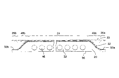
Selon un certain aspect, l'invention concerne un essieu rigide de torsion pour véhicule. L'essieu rigide de torsion comprend une poutre de torsion et un élément de renforcement. La poutre de torsion a un axe longitudinal et a une forme de section transversale généralement concave. L'élément de renforcement s'étend longitudinalement et est relié à la poutre de torsion pour former avec elle une forme tubulaire s'étendant longitudinalement. La poutre de torsion a des première et seconde parois latérales. Au moins une des parois latérales s'étend à l'extérieur de la forme tubulaire. La forme tubulaire a des dimensions en section transversale sélectionnées sur la base du véhicule sur lequel l'essieu rigide de torsion doit être utilisé.


Abrégé anglais

In one aspect, the invention is directed to a twist beam axle for a vehicle. The twist beam axle includes a twist beam and a reinforcement member. The twist beam has a longitudinal axis and has a generally concave cross-sectional shape. The reinforcement member extends longitudinally and is connected to the twist beam to form a longitudinally extending tubular form therewith. The twist beam has first and second side walls. At least one of the side walls extends outside of the tubular form. The tubular form has cross-sectional dimensions that are selected based on the vehicle on which the twist beam axle is to be used.

Revendications

Note : Les revendications sont présentées dans la langue officielle dans laquelle elles ont été soumises.


Claims
What is claimed is:
1. A twist beam axle for a vehicle, comprising:
a twist beam having a longitudinal axis, wherein the twist beam has first and
second side walls and a generally concave cross-sectional shape; and
a reinforcement member that extends longitudinally and is connected to the
twist
beam to form a longitudinally extending tubular form therewith,
said reinforcement member having a central portion and a pair of end portions,
and wherein each end portion has a generally flat control arm attachment
surface for
engagement with a control arm,
wherein at least one of the first and second side walls extends outside of the
tubular form, and
wherein the tubular form has cross-sectional dimensions that are selected in
dependence upon a predetermined stiffness and durability of the vehicle on
which the
twist beam axle is to be used.
2. A twist beam axle as claimed in claim 1, wherein the twist beam defines an
interior,
and wherein the reinforcement member extends along the interior of the twist
beam.
3. A twist beam axle as claimed in claim 2, wherein the first side wall has a
first side
edge, and the second side wall has a second side edge,
wherein the twist beam has a central portion and two end portions,
wherein in the central portion the reinforcement member is connected to the
twist
beam to define the tubular form therewith, and wherein in each of the end
portions the
reinforcement member connects to the twist beam proximate the first and second
side
edges of the first and second side walls in such a way as to define a second
tubular form.
- 7 -

4. A torsional suspension assembly for a vehicle, comprising:
a first control arm and a second control arm;
a vehicle body mounting member connected to each control arm for mounting
pivotally to a body of the vehicle;
a wheel mounting member connected to each control arm for mounting to a
vehicle wheel;
a spring mounting member for receiving an end of a suspension spring; and
a twist beam axle including:
a twist beam having a longitudinal axis, wherein the twist beam has first and
second side walls and a generally concave cross-sectional shape; and
a reinforcement member that extends longitudinally and is connected to the
twist
beam to form a longitudinally extending tubular form therewith,
said reinforcement member having a central portion and a pair of end portions,
and wherein each end portion has a generally flat control arm attachment
surface in
engagement with one of the control arms, and
wherein at least one of the first and second side walls extends laterally
outside of
the tubular form, wherein the tubular form has cross-sectional dimensions that
are
selected in dependence upon a predetermined stiffness and durability of the
vehicle on
which the twist beam axle is to be used.
5. A torsional suspension assembly as claimed in claim 4, wherein the twist
beam defines
an interior, and wherein the reinforcement member extends along the interior
of the twist
beam.
6. A torsional suspension assembly as claimed in claim 5, wherein the first
side wall has a
first side edge, and the second side wall has a second side edge,
wherein the twist beam has a central portion and two end portions,
wherein in the central portion the reinforcement member is connected to the
twist
beam to define the tubular form therewith, and wherein in each of the end
portions the
- 8 -

reinforcement member connects to the twist beam proximate the first and second
side
edges of the first and second side walls in such a way as to define a second
tubular form.
- 9 -

Description

Note : Les descriptions sont présentées dans la langue officielle dans laquelle elles ont été soumises.


CA 02778421 2016-12-16
TUNED TORSION BEAM OF TWIST AXLE
FIELD OF THE INVENTION
[0001] The present invention relates to torsional suspensions for
vehicles and
more particularly to twist beam axles for torsional suspensions.
BACKGROUND OF THE INVENTION
[0002] Twist beam axles are used on some vehicles, typically as a
means of
packaging a suspension while minimizing intrusion into the passenger
compartment. A
typical application of a twist beam axle is on the rear wheels of a vehicle.
The twist
beam axle typically includes a U-shaped or V-shaped bar that extends between
the
control arm for the driver's side rear wheel to the control arm for the
passenger's side
rear wheel. A typical twist beam axle is shown at 100 in Figure 1. The twist
beam axle
100 is shown connected between two control arms 101a and 101b. The twist beam
axle
100 includes a twist beam 102 that is V-shaped in cross-section and a
stabilizer bar 104
in the interior of the V of the twist beam 102. The stabilizer bar 104 may be
welded to
the interior of the V.
[0003] The properties of the stabilizer bar 104 are typically
selected to provide
the twist axle 100 with a selected torsional stiffness to 'tune' the twist
axle 10 for use
on a particular model of vehicle. In some cases the stabilizer bar is made
from solid bar
material. In other cases the stabilizer bar 104 is made from hollow tubing. In
either
case, the resultant twist axle is relatively heavy, and is relatively
expensive to
manufacture.
SUMMARY OF THE INVENTION
[0004] In one aspect, the invention is directed to a twist beam axle
for a vehicle.
The twist beam axle includes a twist beam and a reinforcement member. The
twist
beam has a longitudinal axis and has a generally concave cross-sectional
shape. The
reinforcement member extends longitudinally and is connected to the twist beam
to
form a longitudinally extending tubular form therewith. The twist beam has
first and
second side walls. At least one of the side walls extends outside of the
tubular form.
- 1 -

CA 02778421 2016-12-16
- -
The tubular form has cross-sectional dimensions that are selected in
dependence upon
predetermined stiffness and durability requirements of the vehicle on which
the twist
beam axle is to be used. In another aspect, the invention is directed to a
torsional
suspension assembly including the twist beam axle described above.
10004.11 In accordance with an aspect of at least one embodiment, there is
provided a twist beam axle for a vehicle, comprising: a twist beam having a
longitudinal axis, wherein the twist beam has first and second side walls and
a
generally concave cross-sectional shape; and a reinforcement member that
extends
longitudinally and is connected to the twist beam to form a longitudinally
extending
tubular form therewith, said reinforcement member having a central portion and
a pair
of end portions, and wherein each end portion has a generally flat control arm
attachment surface for engagement with a control arm, wherein at least one of
the side
walls extends outside of the tubular form, and wherein the tubular form has
cross-
sectional dimensions that are selected in dependence upon a predetermined
stiffness
and durability of the vehicle on which the twist beam axle is to be used.
10004.21 In accordance with an aspect of at least one embodiment,
there is
provided a torsional suspension assembly for a vehicle, comprising: a first
control arm
and a second control arm; a vehicle body mounting member connected to each
control
arm for mounting pivotally to a body of the vehicle; a wheel mounting member
connected to each control arm for mounting to a vehicle wheel; a spring
mounting
member for receiving an end of a suspension spring; and a twist beam axle
including: a
twist beam having a longitudinal axis, wherein the twist beam has first and
second side
walls and a generally concave cross-sectional shape; and a reinforcement
member that
extends longitudinally and is connected to the twist beam to form a
longitudinally
extending tubular form therewith, said reinforcement member having a central
portion
and a pair of end portions, and wherein each end portion has a generally flat
control
arm attachment surface in engagement with one of the control arms, and wherein
at
least one of the side walls extends laterally outside of the tubular form,
wherein the
tubular form has cross-sectional dimensions that are selected in dependence
upon a
predetermined stiffness and durability of the vehicle on which the twist beam
axle is to
be used.
- 2 -

CA 02778421 2016-12-16
BRIEF DESCRIPTION OF THE DRAWINGS
[0005] The present invention will now be described by way of example
only
with reference to the attached drawings, in which:
[0006] Figure 1 is an perspective view of a torsional suspension
assembly in
accordance with the prior art;
[0007] Figure 2a is a perspective view a torsional suspension
assembly in
accordance with an embodiment of the present invention;
[0008] Figure 2b is another perspective view of torsional suspension
assembly
shown in Figure 2a;
[0009] Figure 2c is a sectional end view of a twist beam axle that is part
of the
torsional suspension assembly shown in Figure 2a;
[0010] Figure 2d is a perspective view of the twist beam axle shown
in Figure
2c;
[0011] Figure 2e is a sectional side view of the twist beam axle
shown in Figure
2c;
[0012] Figure 3a is a perspective view of a variant of the torsional
suspension
assembly shown in Figure 2a, wherein the twist beam axle is mounted rearwardly
on
the control arms; and
[0013] Figure 3b is a perspective view of another variant of the
torsional
suspension assembly shown in Figure 2a, wherein the twist beam axle is mounted
forwardly on the control arms.
- 2a -

CA 02778421 2012-04-20
WO 2011/050483
PCT/CA2010/001747
Doc. No. 707835PCT
Patent
DETAILED DESCRIPTION OF THE INVENTION
[0014]
Reference is made to Figures 2a and 2b, which show a torsional
suspension assembly 10 for a vehicle, in accordance with an embodiment of the
present
invention. The torsional suspension assembly 10 includes a first control arm
12a and a
second control arm 12b, a first vehicle body mounting member 14a connected to
the
first control arm 12a, a second vehicle body mounting member 14a connected to
the
second control arm 12b, a first wheel mounting member 16a connected to the
first
control arm 12a and a second wheel mounting member 16a connected to the second
control arm 12b, a first spring mounting member 17a and a second spring
mounting
member 17b, and a twist beam axle 18 extending between the first and second
control
arms 12a and 12b.
[0015] The
twist beam axle 18 has a central portion 24, a first end portion 26a,
and a second end portion 26b, at which it connects to the first and second
control arms
12a and 12b. With reference to Figures 2c and 2d, the twist beam axle 18
includes a
twist beam 20 and a reinforcement member 22.
[0016] The
twist beam 20 has a longitudinal axis shown at 28. The twist beam
includes a first side wall 30 and a second side wall 32, and in the embodiment
shown in Figures 2a-2d, the twist beam 20 further includes a base portion 33,
through
which the first and second side walls 30 and 32 are connected to each other.
The base
20 portion
33 in the embodiment shown in Figure 2c is generally arcuate and joins to the
side walls 30 and 32 forming a continuous arcuate shape free of
discontinuities.
[0017] The
base portion 33 in the embodiment shown in Figure 2c is at the top
of the twist beam 20, however, in alternative embodiments that are not shown,
the twist
beam 20 could be oriented so that the base portion 33 is not at the top. For
example,
the twist beam 20 could be oriented so that the base portion 33 is at the
bottom.
[0018] The
twist beam 20 has a generally concave shape. In the embodiment
shown in Figure 2c, it has a downwardly concave shape, however, the twist beam
20
could be oriented so that the concavity faces in another direction. For
example, it could
alternatively have an upwardly concave shape.
- 3 -

CA 02778421 2012-04-20
WO 2011/050483
PCT/CA2010/001747
Doc. No. 707835PCT
Patent
[0019] It
will be noted that, in the context of this description and the appended
claims, having a generally concave shape does not necessarily mean that the
twist beam
20 has an arcuate shape, although the twist beam 20 does have a generally
arcuate
shape in the embodiment shown in Figure 2c. It could alternatively have a non-
arcuate
shape, however, such as an upside-down V-shape, which, in the context of the
present
description and the appended claims, would still constitute a concave shape.
[0020]
The first and second side walls 30 and 32 provide the twist beam with a
selected resistance to bending. The twist beam 20 has a first side edge 34 and
a second
side edge 36. The first and second side edges 34 and 36 may be configured in
any
suitable way. For example, they may be oriented downwards as shown in Figures
2c
and 2d, or, for example, they may be curled upwards (not shown).
[0021]
The reinforcement member 22 extends longitudinally and is connected
to the twist beam 20 to form a longitudinally extending tubular form 38
therewith. The
connection may be any suitable type of connection, such as a welded
connection, a
brazed connection, a connection by mechanical fasteners such as rivets, or any
other
suitable type of connection.
[0022] In
the embodiment shown in Figure 2c, the reinforcement member 22 is
engaged with the base portion 33 and is generally centered with respect to the
twist
beam 20 in the cross-sectional view shown in Figure 2c. As shown, the
reinforcement
member 22 is less wide than the twist beam 20. As a result of that, and as a
result of its
positioning on the twist beam 20, the side walls 30 and 32 of the twist beam
20 extend
outside of the tubular form 38 and extend downwards so as to contribute to the
bending
resistance of the twist beam axle 18. This arrangement yields a mass savings
over a
similar twist beam axle that is formed from a twist beam that has a tubular
form welded
to it.
[0023] By
controlling the cross-sectional dimensions of the tubular form 38 that
is formed, the torsional resistance of the twist beam axle 18 may be
controlled, so as to
tune the twist beam axle 18 for use on different models of vehicle and their
stiffness
and durability requirements. As an example, by increasing the size of the
tubular form
38 the torsional stiffness in general increases.
- 4 -

CA 02778421 2012-04-20
WO 2011/050483
PCT/CA2010/001747
Doc. No. 707835PCT
Patent
[0024] The
cross-sectional dimensions of the tubular form 38 may be controlled
entirely by varying the size and shape of the reinforcement member 22. Thus,
the twist
beam 20 itself may remain entirely the same for each model of vehicle.
[0025] The
twist beam 20 defines an interior 40 (Figure 2e) by virtue of its
concave shape. The reinforcement member 22 is preferably positioned on an
interior
facing surface 42 of the twist beam 20. It is alternatively possible, however,
for the
reinforcement member 22 to be positioned elsewhere on the twist beam 20, such
as on
an exterior facing surface 44.
[0026] As
shown in Figures 2a, 2b and 2d, the side walls 30 and 32 may include
a plurality of lightening holes shown at 46 outside of the tubular form 38 but
spaced
from the side edges 34 and 36. This reduces the weight of the twist beam axle
18,
while having a relatively low impact on its bending resistance and torsional
resistance.
[0027] The
cross-sectional view shown in Figure 2c is in the central portion 24
of the twist beam axle 18. As shown in Figure 2e, the twist beam axle 18
includes
transition portions shown at 48a and 48b in which the reinforcement member 22
transitions outwards (downwards in the views shown in Figures 2c and 2d) to
connect
to the twist beam 20 proximate the side edges 34 and 36, so as to form a base
surface
(shown at 50a at one end and 50b at the other end) for receiving the control
arm. The
base surfaces 50a and 50b facilitate connecting the twist beam axle 18 to the
first and
second control arms 12a and 12b (Figures 2a and 2b).
[0028]
Forming the base surfaces 50a and 50b at each end portion 26a and 26b
directly from the reinforcement member 22 facilitates manufacture of the twist
beam
axle 18.
[0029] The
positions and sizes of the transition portions 48a and 48b can be
tailored as desired to tune the torsional stiffness of the twist beam axle 18.
As a result
of the above described configuration, the twist beam axle 18 is generally free
of crush
zones. Crush zones are shown in some twist beam axles of the prior art, and
are zones
where the reinforcement member 22 and the twist beam 20 are crushed together
in
order to control the torsional resistance of the twist beam axle. A problem
with such
- 5 -

CA 02778421 2012-04-20
=
WO 2011/050483 PCT/CA2010/001747
Doc. No. 707835PCT
Patent
twist beam axles is that they can be susceptible to fatigue in the crush zones
as a result
of the crushing operation itself.
[0030]
As shown in Figures 2a and 2b, the twist beam axle 18 may be centrally
mounted on the control arms 12a and 12b. It is alternatively possible for the
twist beam
axle 18 to be rearwardly mounted as shown in Figure 3a, wherein it is mounted
to
rearward portions of the control arms 12a and 12b. It is alternatively
possible for the
twist beam axle 18 to be forwardly mounted as shown in Figure 3b, wherein it
is
mounted to forward portions of the control arms 12a and 12b.
[0031]
The twist beam 20 and the reinforcement member 22 may be made from
any suitable materials, such as from an automotive grade of steel, suitably
treated for
exposure to the elements during use.
[0032]
While the above description constitutes a plurality of embodiments of
the present invention, it will be appreciated that the present invention is
susceptible to
further modification and change without departing from the fair meaning of the
accompanying claims.
- 6 -

Dessin représentatif
Une figure unique qui représente un dessin illustrant l'invention.
États administratifs

2024-08-01 : Dans le cadre de la transition vers les Brevets de nouvelle génération (BNG), la base de données sur les brevets canadiens (BDBC) contient désormais un Historique d'événement plus détaillé, qui reproduit le Journal des événements de notre nouvelle solution interne.

Veuillez noter que les événements débutant par « Inactive : » se réfèrent à des événements qui ne sont plus utilisés dans notre nouvelle solution interne.

Pour une meilleure compréhension de l'état de la demande ou brevet qui figure sur cette page, la rubrique Mise en garde , et les descriptions de Brevet , Historique d'événement , Taxes périodiques et Historique des paiements devraient être consultées.

Historique d'événement

Description Date
Le délai pour l'annulation est expiré 2021-08-31
Inactive : COVID 19 Mis à jour DDT19/20 fin de période de rétablissement 2021-03-13
Lettre envoyée 2020-11-02
Lettre envoyée 2020-08-31
Inactive : COVID 19 - Délai prolongé 2020-08-19
Inactive : COVID 19 - Délai prolongé 2020-08-06
Inactive : COVID 19 - Délai prolongé 2020-07-16
Inactive : COVID 19 - Délai prolongé 2020-07-02
Inactive : COVID 19 - Délai prolongé 2020-06-10
Inactive : COVID 19 - Délai prolongé 2020-05-28
Inactive : COVID 19 - Délai prolongé 2020-05-14
Inactive : COVID 19 - Délai prolongé 2020-04-28
Lettre envoyée 2019-11-01
Représentant commun nommé 2019-10-30
Accordé par délivrance 2017-11-28
Inactive : Page couverture publiée 2017-11-27
Préoctroi 2017-10-17
Inactive : Taxe finale reçue 2017-10-17
Lettre envoyée 2017-06-06
Un avis d'acceptation est envoyé 2017-06-06
Inactive : Lettre officielle 2017-06-06
Inactive : Q2 réussi 2017-04-21
Inactive : Approuvée aux fins d'acceptation (AFA) 2017-04-21
Modification reçue - modification volontaire 2016-12-16
Inactive : Dem. de l'examinateur par.30(2) Règles 2016-06-28
Inactive : Rapport - Aucun CQ 2016-06-28
Modification reçue - modification volontaire 2015-12-03
Lettre envoyée 2015-07-16
Requête d'examen reçue 2015-07-02
Exigences pour une requête d'examen - jugée conforme 2015-07-02
Toutes les exigences pour l'examen - jugée conforme 2015-07-02
Inactive : Page couverture publiée 2012-07-11
Inactive : CIB en 1re position 2012-06-13
Lettre envoyée 2012-06-13
Inactive : Notice - Entrée phase nat. - Pas de RE 2012-06-13
Inactive : CIB attribuée 2012-06-13
Demande reçue - PCT 2012-06-13
Exigences pour l'entrée dans la phase nationale - jugée conforme 2012-04-20
Demande publiée (accessible au public) 2011-05-05

Historique d'abandonnement

Il n'y a pas d'historique d'abandonnement

Taxes périodiques

Le dernier paiement a été reçu le 2017-09-12

Avis : Si le paiement en totalité n'a pas été reçu au plus tard à la date indiquée, une taxe supplémentaire peut être imposée, soit une des taxes suivantes :

  • taxe de rétablissement ;
  • taxe pour paiement en souffrance ; ou
  • taxe additionnelle pour le renversement d'une péremption réputée.

Les taxes sur les brevets sont ajustées au 1er janvier de chaque année. Les montants ci-dessus sont les montants actuels s'ils sont reçus au plus tard le 31 décembre de l'année en cours.
Veuillez vous référer à la page web des taxes sur les brevets de l'OPIC pour voir tous les montants actuels des taxes.

Historique des taxes

Type de taxes Anniversaire Échéance Date payée
Taxe nationale de base - générale 2012-04-20
Enregistrement d'un document 2012-04-20
TM (demande, 2e anniv.) - générale 02 2012-11-01 2012-09-14
TM (demande, 3e anniv.) - générale 03 2013-11-01 2013-09-30
TM (demande, 4e anniv.) - générale 04 2014-11-03 2014-09-23
Requête d'examen (RRI d'OPIC) - générale 2015-07-02
TM (demande, 5e anniv.) - générale 05 2015-11-02 2015-09-22
TM (demande, 6e anniv.) - générale 06 2016-11-01 2016-09-07
TM (demande, 7e anniv.) - générale 07 2017-11-01 2017-09-12
Taxe finale - générale 2017-10-17
TM (brevet, 8e anniv.) - générale 2018-11-01 2018-10-11
Titulaires au dossier

Les titulaires actuels et antérieures au dossier sont affichés en ordre alphabétique.

Titulaires actuels au dossier
MAGNA INTERNATIONAL INC.
Titulaires antérieures au dossier
ALEXANDER ZAK
JAMES R., II BYRNE
NIKHIL MADAN YARDI
SEETARAMA S . KOTAGIRI
YING ZHANG
Les propriétaires antérieurs qui ne figurent pas dans la liste des « Propriétaires au dossier » apparaîtront dans d'autres documents au dossier.
Documents

Pour visionner les fichiers sélectionnés, entrer le code reCAPTCHA :


Pour visualiser une image, cliquer sur un lien dans la colonne description du document. Pour télécharger l'image (les images), cliquer l'une ou plusieurs cases à cocher dans la première colonne et ensuite cliquer sur le bouton "Télécharger sélection en format PDF (archive Zip)" ou le bouton "Télécharger sélection (en un fichier PDF fusionné)".

Liste des documents de brevet publiés et non publiés sur la BDBC .

Si vous avez des difficultés à accéder au contenu, veuillez communiquer avec le Centre de services à la clientèle au 1-866-997-1936, ou envoyer un courriel au Centre de service à la clientèle de l'OPIC.


Description du
Document 
Date
(aaaa-mm-jj) 
Nombre de pages   Taille de l'image (Ko) 
Description 2012-04-19 6 268
Dessins 2012-04-19 5 152
Dessin représentatif 2012-04-19 1 11
Revendications 2012-04-19 2 75
Abrégé 2012-04-19 1 64
Revendications 2016-12-15 3 83
Description 2016-12-15 7 317
Dessin représentatif 2017-11-01 1 7
Avis d'entree dans la phase nationale 2012-06-12 1 192
Courtoisie - Certificat d'enregistrement (document(s) connexe(s)) 2012-06-12 1 104
Rappel de taxe de maintien due 2012-07-03 1 112
Rappel - requête d'examen 2015-07-05 1 124
Accusé de réception de la requête d'examen 2015-07-15 1 187
Avis du commissaire - Demande jugée acceptable 2017-06-05 1 164
Avis du commissaire - Non-paiement de la taxe pour le maintien en état des droits conférés par un brevet 2019-12-12 1 544
Courtoisie - Brevet réputé périmé 2020-09-20 1 552
Avis du commissaire - Non-paiement de la taxe pour le maintien en état des droits conférés par un brevet 2020-12-20 1 544
PCT 2012-04-19 9 319
Requête d'examen 2015-07-01 1 28
Modification / réponse à un rapport 2015-12-02 1 24
Demande de l'examinateur 2016-06-27 3 194
Modification / réponse à un rapport 2016-12-15 9 278
Courtoisie - Lettre du bureau 2017-06-05 2 59
Taxe finale 2017-10-16 1 26