Note : Les descriptions sont présentées dans la langue officielle dans laquelle elles ont été soumises.
CA 02778444 2012-04-19
WO 2011/050241 PCT/US2010/053684
FLUID ACTUATED VALVE AND INSTALLATION TOOL
CROSS-REFERENCE TO RELATED APPLICATION(S)
The present application derives priority from U.S. provisional patent
application serial
no. 61/279,552 filed 22-October-2009.
BACKGROUND OF THE INVENTION
1. Field of the Invention
The present invention relates to valves and, more particularly, to a fluid
(hydraulic or
pneumatic) actuated valve.
2. Description of the Background
Directly operated, or actuated, fluidic valves are well known in the art for
controlling
the flow of gas, air or fluid there through. Such valves typically include a
valve body having
a flow passage formed through the valve body. A valve member is supported
within the flow
passage and moveable from one position to another to regulate fluid flow in
direct response
to an operative force placed on the valve member by an actuator. A plurality
of ports are
provided to connect the valve assembly to a pressurized fluid supply as well
as to the various
active devices that the valve may control. The actuator is typically an
electromagnetically or
piezo-electric solenoid that is energized to move the valve member to a
predetermined
position within the flow passage. A return spring is often employed to bias
the valve member
back to a known non-energized position. Valves of this type are employed in a
wide variety
of manufacturing environments where high flow rates and fast response times
are desired.
Exemplary of such valves is the fail-open solenoid actuated valve of William
R.
Hayes embodied in U.S. Patent 5,413,308 (1995). The Hayes valve is a spring
biased
normally open solenoid actuated valve that includes a valve body having a
valve seat defining
1
CA 02778444 2012-04-19
WO 2011/050241 PCT/US2010/053684
a valve port located between an fluid inlet port and a fluid outlet port. A
sealing member on a
rod under the control of a spool is longitudinally moveable into our out of
the valve port to
control fluid flow. When the solenoid is de-energized, the valve spool is
biased open by a
compression spring. The sealing member contacts the inner valve seat when the
solenoid is
energized thus closing the valve. When the solenoid is deactivated
intentionally or due to an
electrical failure the valve fails to an open position.
Such valves are used in a wide variety of contexts ranging from engines to
industrial
systems to pneumatic tools. The operating parameters for such systems are
growing
increasingly stringent as designers attempt to make them faster, less
expensive and
lightweight. This places increasing demands on the valves used for such
systems.
Manufacturers now require control valves that can provide extremely fast
positive shutoff,
and turn on, within a few milliseconds. This speed is very difficult to
achieve in a fluid
valve.
Other examples of fluid control valves by the present inventors include a
pneumatically actuated valve for internal combustion engines described in U.S.
Patent
7,140,332, issued November 28, 2006 and an automatic, pressure responsive air
intake valve
for internal combustion engine described in U.S. Patent 6,349,691 issued
February 26, 2002,
each of which are incorporated herein by reference. U.S. Patent 6,349,691
discloses an
automatically actuated, pressure responsive air intake valve for an internal
combustion engine
generally having a fixed valve seat housing and a sliding valve member. The
valve seat
housing is threaded into the head of a working chamber on an internal
combustion engine.
The sliding valve member reciprocates through the housing in response to
differential
pressures on either side of the valve. The sliding member has a hollow chamber
that opens in
a sidewall of the valve seat housing, thereby directing a stream of air
outward from the valve
2
CA 02778444 2012-04-19
WO 2011/050241 PCT/US2010/053684
structure. U.S. Patent 7,140,332, discloses a pneumatically actuated valve
assembly for use as
intake and/or exhaust valves on internal combustion engines. The assembly
includes a valve,
valve housing, and compressed gas distribution and timing mechanisms. The
valve is
comprised of a short light weight hollow cylindrical body with a capped lower
end and an
opened upper end. The valve is further defined by a plurality of ports
adjacent to the lower
end and a collar encircling the body adjacent the upper end. The valve housing
is hollow and
tubular having a larger diameter upper section and a smaller diameter lower
section in which
the valve slides up to close and down to open. The housing further includes
hollow channels
which direct compressed gas, managed by the distribution and timing mechanism,
alternately
towards the areas above and below the valve collar at regular intervals to
open and close the
valve, respectively.
SUMMARY OF THE INVENTION
The object of the present invention is a direct fluid-actuated valve assembly
that can
provide extremely fast positive shutoff, and turn on, within a few
milliseconds. The valve
assembly includes a valve housing having an internal fluid port defined by a
larger chamber
and an adjacent smaller chamber demarcated by a shoulder, a valve body seated
in the valve
housing and defined by a plurality of ports evenly spaced circumferentially
around its
circumference a plurality of supporting wall sections (mullions) between the
ports, and a
plurality of internal vanes each running along a corresponding mullion for
reinforcement
thereof, said vanes being inclined and/or curved to promote a circular
internal fluid flow
within the valve body. A valve cap with annular collar is affixed to the valve
body, and the
valve body and cap/collar are slidably carried in the valve housing between an
open position
and a closed position.
3
CA 02778444 2012-04-19
WO 2011/050241 PCT/US2010/053684
A toolset is also disclosed for easily installing and removing the valve
assembly. The
toolset includes a valve wrench designed to mate with the collar and having an
elongate
handle for manual turning, and an open circular head defined by a plurality of
interlocking
features. The toolset also includes a chuck formed as an extended stem leading
to a disk
defined by a series of notches, the stem having a keyed cross-section, and the
disk having
notches conforming to the vanes of said valve body to grip the vanes and
stabilize the valve
body. The chuck protrudes up through the circular wrench head and can be held
by a
standard wrench, or other means, to stabilize the valve body while the valve
wrench is turned
to detach the collar.
BRIEF DESCRIPTION OF THE DRAWINGS
FIG. 1 depicts the structural features of an exemplary pneumatically actuated
valve
according to the present invention.
FIG. 2 is an enlarged illustration of the valve body 2.
FIG. 3 is a top view of the valve body 2.
FIG. 4 is a cross-sectional perspective view of an assembled single acting
valve body
with valve body cap with collar affixed, seated in the valve housing in a
closed position.
FIG. 5 is a cross-sectional perspective view of an assembled single acting
valve body
with valve body cap with collar affixed, seated in the valve housing in an
open position.
FIG. 6 is a cross-sectional drawing of an assembled double acting valve
according to
the present invention in an open position.
FIG. 7 is a cross-sectional drawing of the double acting valve according to
the present
invention in a closed position.
4
CA 02778444 2012-04-19
WO 2011/050241 PCT/US2010/053684
FIG. 8 is an exploded view of a single acting valve according to the present
invention
inclusive of the valve wrench and chuck tools for installation and/or removal.
FIG. 9 is an enlarged side (A) and bottom (B) view of the chuck of FIG. 8.
DETAILED DESCRIPTION OF THE PREFERRED EMBODIMENT
The present invention is a fast acting fluid actuated valve assembly. The
invention is
depicted in the context of a pneumatic valve directly actuated by means of
forced or
compressed air, although one skilled in the art will recognize that other
pressurized gases or
fluids may be suitable for actuating the valve of the present invention. With
reference to FIG.
1, the structural features of an exemplary pneumatically actuated valve
according to the
present invention are depicted which generally include a valve housing 1, a
valve body 2
seated in the valve housing 1 and having a cap 7 with annular collar 8 affixed
to the valve
body 2. The various components are described in more detail as follows.
As seen in FIG. 2, the valve body 2 is a hollow, cylindrical body with an
upper end
and a lower end. The lower end is capped by an endplate 4 forming a valve body
seat that
defines a floor to the valve body 2. The endplate 4 is beveled about the upper
surface of its
peripheral edge with a bevel of approximately 45 degrees to seat against a
cooperative bevel
in the valve housing 1. The endplate rises from the beveled peripheral edge 4
inwardly
toward the center at an angle of between 0 and 25 0 degrees, inclusive, and
preferably
approximately a 10 degrees. The valve body 2 is further defined by a plurality
of ports 3a
around its circumference, adjacent the endplate 4. Preferably, three uniformly
oblong ports
3a are provided at a uniform angular spacing, and all opening into the hollow
interior of the
valve body 2. The ports 3a are segregated by partitions or "mullions" 3 formed
in the walls
of the valve body 2. Each mullion 3 is relatively thin compared to the breadth
of the ports 3a.
5
CA 02778444 2012-04-19
WO 2011/050241 PCT/US2010/053684
The horizontal extent of each mullion 3 is approximately 15% that of each
neighboring port
3a, such that the portion of the circumference occupied by the mullions 3 is
15% the total
circumference of the valve body 2. This minimizes the obstruction by the
mullions 3 and
maximizes air/fluid flow through the ports 3a.
Under normal conditions, mullions 3 of this magnitude might be insufficient to
support the endplate 4 under the operating stresses imposed on the valve.
However, the
mullions 3 are further defined by integral vanes 9 which extend internally
into the valve body
2 and which add additional support. Each vane 9 originates proximate the upper
end of the
valve body 2 and terminates at endplate 4, running more or less lengthwise
down a
corresponding mullion 3. From top to bottom each vane 9 begins as a shallow
inward
protuberance and gradually ramps outward toward the bottom where it occupies,
in certain
embodiments, approximately '/2 or more of the radius of the valve body 2. In
addition, from
proximate the valve body 2 wall to the innermost edge of the vane 9, each vane
9 adapts a
slight angle to induce a circular air/fluid flow within the valve body 2. In
further addition,
each vane 9 runs top to bottom at a slight angular offset from vertical and
mushrooms to a
broader base at its juncture with endplate 4. The innermost edge of the vane 9
is rounded, all
of the foregoing features contributing to proper airflow. The vanes 9 are
preferably integrally
molded to the valve body 2 and each vane 9 adds reinforcement to the mullion
3, preventing
collapse. The valve body 2 is preferably threaded 11 externally around the
upper end of the
valve body 2 to affix the cap 7.
FIG. 3 is a top view of the valve body 2 illustrating the contour of each vane
9
provided in certain embodiments to induce a circular air/fluid flow within the
valve body 2.
The vanes 9 in such embodiments are each oriented radially inward along an
axis x which is
at an angle a of 10-15 degrees from the radial axis R of the valve body 2
(shown by angle
6
CA 02778444 2012-04-19
WO 2011/050241 PCT/US2010/053684
lines). FIG. 4 is a cross-sectional perspective of the assembled valve body 2
seated in the
valve housing 1, with valve body cap 7 (and integral collar 8) affixed to the
valve body 2.
The vanes 9 are each downwardly oriented along an axis y which forms an angle
(3 of 10-15
degree offset from vertical axis A through the valve body 2. The combination
of the x and (3
angular offsets, together with the rounded innermost edge of the vanes 9 and
their broader
contoured juncture with endplate 4 serves to deflect downward air/fluid flow
laterally to
induce a swirling circular air/fluid flow within the valve body 2.
The valve housing 1 may be any supporting structure, e.g., an engine block or
cylinder head, made, machined, molded or otherwise formed with a suitable port
for
accepting the assembled valve body 2. The port is machined as a two-tiered
cylindrical port
with a larger upper diameter abutting a constricted lower diameter at a
shoulder 13, the upper
diameter defining a barrel for flush sliding of the valve body cap 7 and
collar 8 (and valve
body 2), and the barrel space between the shoulder 13 and the collar 8
defining a first
"control volume" 20A. The shoulder 13 limits downward motion of the cap
7/collar 8 and
body 2, and seats the valve body cap 7 and collar 8 when the valve is in the
open (down)
position.
FIG. 5 illustrates the assembled valve body 2 and valve body cap 7 with collar
8 as in
FIG. 4 seated in the valve housing 1, here in an open position. The valve body
cap 7 with
collar 8 (and valve body 2) slide downward until the collar 8 abuts the
shoulder 13 in the port
of valve housing 1, resulting in a minimal control volume 20A. This extends
the endplate 4
beneath the valve body 1 opening the ports 3a for fluid flow (air, gas or
liquid).
Note that the first control volume 20A in FIG. 5 is near zero because the
valve is shown in an
open position, but the first control volume 20A increases as the valve closes.
As noted, the
lower rim 5 of the port in valve housing 1 is formed with a bevel to match
that of the endplate
7
CA 02778444 2012-04-19
WO 2011/050241 PCT/US2010/053684
4 for flush seating of the valve body 2 against the valve housing 1 when the
valve is in a
closed position, as seen in FIG. 4. The overall length of the valve is
relatively short and wide,
compared to conventional direct valves which generally feature long thin
bodies. The wide
cylindrical valve body 2 of the present valve makes the valve less likely to
suffer the effects
of wear and tear as compared to conventional valves.
In a double or two-way acting embodiment of the present invention forced fluid
such
as compressed air or other gas is used to both open and close the valve. In
this case there are
two actuation areas, one above and one below the collar 8. The valve is closed
by directing
forced air below the collar 8, thereby exerting pressure to the underside of
the collar 8
causing the valve to move upward and closed. For this purpose the embodiment
shown in
FIGs. 1-5 may additionally employ a housing cap 19 fixedly attached to the
valve housing 1
to prevent withdrawal, as described below.
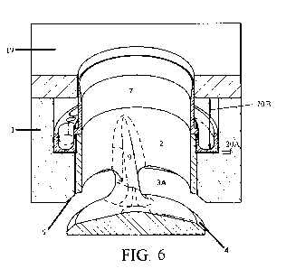
FIG. 6 is a cross-sectional drawing of an assembled two-way valve according to
the
present invention, in an open position while FIG. 7 shows the valve in a
closed position. The
housing cap 19 here is a solid wall attached to and covering the valve housing
1 but defined
by an open aperture so as not to cover the open port. The inner cylindrical
wall of the valve
body cap 7 is extended in height to pass through the housing cap 19. Thus, the
housing cap
19 serves as a guide bushing for the valve body cap 7. The height of the
extended valve body
cap 7 should be sufficient so that it never drops below the lower surface of
the housing cap
19. This way, since the housing cap 19 is affixed to the valve housing 1, the
valve body 2
cannot be withdrawn. In use, the valve housing 1 port is connected to a forced
fluid (air, gas
or liquid) source. When the valve is closed (FIG. 7), forced air directed into
the port exerts
pressure onto the end plate 4 and valve body 2, downward and open.
8
CA 02778444 2012-04-19
WO 2011/050241 PCT/US2010/053684
As above, the valve body cap 7 with collar 8 (and valve body 2) slide downward
until
the collar 8 abuts the shoulder 13 in the port of valve housing 1. This
extends the endplate 4
beneath the valve body 1 opening the ports 3a for fluid flow (air, gas or
liquid). Again, the
barrel space between the shoulder and the collar 8 defines the first "control
volume" 20A.
The shoulder 13 limits downward motion of the cap 7/collar 8 and body 2, and
seats the valve
body cap 7 and collar 8 when the valve is in the open (down) position. The
first control
volume 20A in FIG. 6 is near zero because the valve is shown in an open
position, but the
first control volume 20A increases (FIG. 7) as the valve closes. For the two-
way valve, a
second control volume 20B of the valve body 2 is defined within the barrel by
the upper
surface of the collar 8 and the lower surface of the housing cap 19. The
second control
volume 20B in FIG. 6 is near maximum because the valve is shown in an open
position, but
the second control volume 20B decreases (FIG. 7) as the valve closes. In the
preferred
embodiment, the maximum vertical extent of the control volumes 20A, 20B of the
valve body
2 are approximately equal to one-half the length of the valve body 2.
In either one-way or two-way valve operation, a return spring may be loaded
into the
valve body 2, possibly but not necessarily one side or the other of the collar
8, to bias the
valve member back to either open or closed positions, further improving
response time.
Generally, a forced air distribution system with electronic solenoids or piezo-
electric
valves will be used to control the disclosed valve. For example, compressed
air is input
through a one-way valve to prevent losses due to back pressure. A programmable
electronic
control module manages the distribution and timing of the flow of forced air
as needed. The
air may be forwarded through a manifold and thereby gated through to a
plurality of the
valves according to the present invention. The gates may be solenoids or piezo-
electric
valves under control of the programmable electronic control module. Those
skilled in the art
9
CA 02778444 2012-04-19
WO 2011/050241 PCT/US2010/053684
will recognize that a variety of conventional electronic, electromechanical,
electromagnetic
and piezo air distribution schemes exist and are considered standard equipment
for fluid
actuated valve systems.
The above-described valve confers another advantage in that its design greatly
facilitates installation and removal. In the context of the embodiment shown
in FIGs. 1-5,
FIG. 8 illustrates this premise with a unique valve wrench 18 designed to mate
with the collar
8 of valve body cap 7, and a chuck 6. For this purpose, the upward-facing
surface of the
collar 8 is defined by a series of interlocking features such as apertures (as
shown), notches or
protuberances. The valve wrench 18 is defined by an elongate handle for manual
turning,
and an open circular head likewise adorned with a cooperating series of
interlocking features
such as posts (as shown) to fit into the apertures of the collar 8 of valve
body cap 7, or
notches or other protuberances, etc.
FIG. 9 is an enlarged side (A) and bottom (B) view of the chuck 6. The chuck 6
includes an extended stem leading to a disk defined by a series of notches.
The stem is
defined by a keyed cross-section as shown. The chuck 6 is intended to maintain
the valve
body 2 stationary while the valve body cap 7 and collar 8 are removed, and the
chuck 6 is
inserted downwardly into the valve body 2. The notches in chuck 6 conform to
the interior
vanes 9 and grip the vanes 9 such that maintaining the chuck stationery holds
the valve body
2 stationary. The valve wrench 18 is inserted over the chuck 6 with the chuck
6 protruding
upward through the open valve wrench 18. The cooperating series of
interlocking features
(posts or otherwise) fit into the apertures of the collar 8 and provide
turning leverage. Since
the chuck 6 protrudes upward through the open valve wrench 18, a standard
wrench may be
used to maintain the chuck 6 stationery while the valve wrench 18 is turned to
unscrew the
CA 02778444 2012-04-19
WO 2011/050241 PCT/US2010/053684
valve body cap 7 and collar 8 from the valve body 2. This design greatly
facilitates
installation and removal.
The above-described embodiments of the present invention, inclusive of the
fluid
actuated valve itself, plus installation/removal wrench and chuck, solve the
problems and
eliminate the disadvantages associated with conventional direct valves. They
provide an
assembly that is simple and straightforward, fabricated of strong, durable,
resilient materials
appropriate to the nature of their usage, and may be economically manufactured
and sold.
Having now fully set forth the preferred embodiment and certain modifications
of the
concept underlying the present invention, various other embodiments as well as
certain
variations and modifications of the embodiments herein shown and described
will obviously
occur to those skilled in the art upon becoming familiar with said underlying
concept. It is to
be understood, therefore, that the invention may be practiced otherwise than
as specifically
set forth in the appended claims.
INDUSTRIAL APPLICABILITY
Directly operated, or actuated, fluidic valves are employed in a wide variety
of
manufacturing environments where high flow rates and fast response times are
desired.
Such valves are used in a wide variety of contexts ranging from engines to
industrial systems
to pneumatic tools. The operating parameters for such systems are growing
increasingly
stringent as designers attempt to make them faster, less expensive and
lightweight. This
places increasing demands on the valves used for such systems. Manufacturers
now require
control valves that can provide extremely fast positive shutoff, and turn on,
within a few
milliseconds. This speed is very difficult to achieve in a fluid valve.
Consequently, there
11
CA 02778444 2012-04-19
WO 2011/050241 PCT/US2010/053684
would is significant industrial applicability for a direct fluid-actuated
valve assembly that can
provide extremely fast positive shutoff, and turn on, within a few
milliseconds.
12