Note : Les descriptions sont présentées dans la langue officielle dans laquelle elles ont été soumises.
CA 02780885 2012-08-22
TITLE: VIBRATING DOWNHOLE TOOL
INVENTOR: CHARLES ABERNETHY ANDERSON
BACKGROUND OF THE DISCLOSURE
Field of Disclosure
The present disclosure relates to vibrating tools in general, and in
particular to a method and apparatus for vibrating a downhole tool in a drill
string.
Description of Related Art
In the field of drilling, friction may frequently impair the ability of the
drill string to be advanced within the hole. For example, highly deviated
holes
or horizontal drilling cannot rely on the weight of the drill pipe alone to
overcome friction from the horizontal pipe resting against the wall of the
hole.
Conventional vibration tools have alternatingly increased the
pressure of the drilling fluid within the drill string by cyclically blocking
and
unblocking the flow of the drilling fluid within the drill string. Such
devices
accordingly cyclically increase the pressure of the drilling fluid within the
drill
string and then release it. Such devices disadvantageously require a high
supply pressure over and above the supply pressure for the drilling fluid.
This
increases cost and complexity of the machinery required to support this
operation. In addition, many conventional vibration tools involve complex
downhole systems and devices which may be more prone to breakage.
Many such conventional vibration tools also create backpressure in
the drilling fluid supply. This has the negative consequences of requiring
supply pumps of greater capacity and also reduces the supply pressure to the
drilling bit. Still other apparatuses have utilized blunt mechanical impacts
which increases the wear life and the complexity of the design.
SUMMARY OF THE DISCLOSURE
In some embodiments there is disclosed a method of vibrating a
downhole drill string. The method can comprise pumping a drilling fluid down
;E6242558 DOC, 1)
CA 02780885 2012-08-22
2
the drill string and cyclically venting the drilling fluid through a valve
disposed
in a side wall of the drilling string so as to cyclically reduce the pressure
of the
drilling fluid in the drill string.
In some embodiments, the method can further comprise rotating at
least one rotor within a tubular body disposed in-line within the drill string
wherein the venting can comprise intermittently passing the drilling fluid
through a rotor port disposed in the rotor and a corresponding tubular body
port disposed in the tubular body. The rotor can be rotated by the drilling
fluid.
In some embodiments, the method can further comprise separating
the drilling fluid into a central bypass portion and an annular rotor portion,
the
bypass portion can flow past the rotor, and the rotor portion can rotate the
rotor. The bypass portion and the rotor portion can be combined after the
rotor portion rotates the rotor, wherein the combined rotor portion and the
bypass portion can pass through the rotor port and the tubular port.
According to a further embodiment, there is disclosed an apparatus
for vibrating a downhole drill string. The drill string is operable to have a
drilling fluid pumped therethrough. The apparatus can comprise a tubular
body securable to the drill string and having a central bore therethrough, a
valve disposed in the tubular body for venting the drilling fluid out of the
drill
string and a valve actuator for cyclically opening and closing the valve.
The valve can comprise a radial tubular body port in the tubular
body and at least one rotor located within the central bore having a radial
rotor
port wherein the rotor port is selectably alignable with the tubular body port
as
the rotor rotates within the central bore. The valve actuator can comprise at
least one vane on the rotor for rotating the rotor as the drilling fluid flows
therepast. The rotor can include a central bypass bore therethrough and a
plurality of vanes radially arranged around the central bypass bore.
The apparatus can further comprise a separator for separating the
drilling fluid into a bypass portion and a rotor portion secured within the
central
bore, the rotor portion being directed onto the plurality of vanes so as to
rotate
the rotor, the bypass portion being directed though the bypass bore of the
(E6242558 DOC; I)
CA 02780885 2012-08-22
3
rotor. The separator can include a central bypass port and an annular rotor
passage therearound. The separator can be located adjacent to the rotor
such that the central bypass port of the separator directs the bypass portion
of
the drilling fluid though the bypass bore of the rotor and wherein the rotor
passage of the separator directs the rotor portion of the drilling fluid onto
the
plurality of vanes of the rotor. The rotor passage of the separator can
include
stator vanes for directing the rotor portion of the drilling fluid onto the
plurality
of vanes.
The apparatus can further comprise a plurality of rotor ports
selectably alignable with a plurality of tubular body ports. Each of the
plurality
of rotor ports can be selectably alignable with a unique tubular body port.
The tubular body can be connectable inline within a drill string. The
tubular body can include threaded end connectors for linear connection within
a drill string.
The bypass port of the separator can include an inlet shaped to
receive a blocking body so as to selectably direct more drilling fluid through
the rotor passage. The inlet can have a substantially spherical shape so as to
receive a spherical blocking body.
Other aspects and features of the present invention will become
apparent to those ordinarily skilled in the art upon review of the following
description of specific embodiments of the invention in conjunction with the
accompanying figures.
E6242558 DOC, 11
CA 02780885 2012-08-22
4
BRIEF DESCRIPTION OF THE DRAWINGS
In drawings which illustrate embodiments of the invention wherein
similar characters of reference denote corresponding parts in each view,
Figure 1 is a perspective view of the vibrating downhole tool
located within a drill string.
Figure 2 is a partial cross-sectional perspective view of a
vibrating downhole tool according to an embodiment.
Figure 3 is a perspective view of a separator of the apparatus of
Figure 2.
Figure 4 is a perspective view of a rotor of the apparatus of
Figure 2.
Figure 5 is a cross sectional view of the apparatus of Figure
2
taken along the line 5-5 with the rotor at a first position.
Figure 6 is a cross sectional view of the apparatus of Figure
2
taken along the line 5-5 with the rotor at a second
position.
Figure 7 is a perspective view of the flow separator of the
apparatus of Figure 2 according to a further
embodiment.
Figure 8 is a partial cross-sectional perspective view of a
vibrating downhole tool according to a further
embodiment.
Figure 9 is a partial cross-sectional perspective view of a
vibrating downhole tool according to a further
embodiment.
Figure 10 is a cross sectional view of the apparatus of Figure
9.
Figure 11 is a partial cross-sectional perspective view of the
apparatus of Figure 9.
Figure 12 is a partial cross-sectional view of a vibrating
downhole
tool according to a further embodiment.
E6242558 DOC. 1)
CA 02780885 2012-08-22
Figure 13 is a cross sectional view of the apparatus of Figure
12.
DETAILED DESCRIPTION
Referring to Figure 1, a drill string 10 is illustrated down a bore hole
5 8 in a soil or rock formation 6. The drill string includes a drill bit 12
at a lower
end 14 thereof and an apparatus according to an embodiment shown
generally at 20 for vibrating the drill string within the bore hole 8. The
apparatus 20 can be located proximate to the lower end 14 of the drill string
or at an intermediate portion 16 of the drill string 10. It will also be
10 appreciated that a plurality of apparatuses 20 can be located at a
plurality of
locations along the drill string.
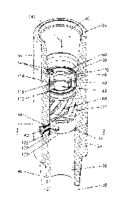
Turning now to Figure 2, the apparatus 20 comprises a tubular body
30, a flow separator 60 and a rotor 80. The tubular body 30 has a cylindrical
wall 31 having inner and outer surfaces 32 and 34, respectively extending
between inlet and outlet ends, 36 and 38, respectively. The inner surface 32
defines a central bore 40. The tubular body 30 includes at least one radial
tubular body port 42 extending therethrough. The tubular body port 42 can be
formed as a bore through the wall 31 or can optionally be located within a
tubular body port insert 44 as illustrated in Figure 2. The use of a tubular
body port insert 44 facilitates the interchangability of tubular body port 42
of
differing sizes as will be further described below.
As illustrated the tubular body port insert 44 can be threadably
secured within the wall 31 or by any other suitable means, such as by way of
non-limiting example, compression fit, latches, retaining clips or the like.
As
illustrated, the tubular body port 42 can have a throttling cross section such
that the tubular body port 42 is wider proximate to the interior surface 32 of
the tubular body than proximate to the exterior surface 34. The use of a
throttling cross section will assist in controlling the volume of drilling
fluid
vented therethrough. The tubular body port insert 44 can be sealed to the
tubular body 30 with an o-ring to prevent washout and backed with a snap
ring to prevent the tubular body port insert 44 from backing out.
The inlet and outlet ends 36 and 38 of the tubular body 30 can
:E6242558 DOC, 1)
CA 02780885 2012-08-22
6
include interior and exterior threading 46 and 48, respectively, for securing
the
tubular body in-line with the drill string 10. It will be appreciated that the
interior and exterior threading 46 and 48 will be of a conventional type, such
as a pin/box type to facilitate ready connection with the drill string 10. The
tubular body 30 can be of steel construction, or of any other suitable
material,
and can be surface hardened for durability and abrasion resistance.
The flow separator 60 comprises a disk shaped body having a
central bypass passage 62 and a plurality of rotor passages 64 distributed
radially around the bypass passage. The flow separator 60 is sized to be
located within the central bore 40 of the tubular body as illustrated in
Figure 2.
Turning now to Figure 3, the flow separator 60 comprises an outer
cylinder 66 and an inner cylinder 68 with a plurality of radial support arms
70
extending therebetween. The outer cylinder 66 includes an outer surface 72
sized to be securely received within the central bore 40 of the tubular body
30.
The inner cylinder includes an inner surface 74 defining the bypass passage.
The inner cylinder 68, outer cylinder 66 and the support arms 70 define the
rotor passages 64.
With reference to Figure 4, the rotor 80 comprises a substantially
cylindrical body having inlet and outlet sections, 82 and 84, respectively and
a
turbine section 86 therebetween. The rotor inlet section 82 of the rotor
comprise an outer sleeve 90 and a bypass cylinder 88 defining an annular
rotor passage 92 therebetween. The outer sleeve 90 includes an outer
surface 104. The bypass cylinder 88 defines a bypass passage 94
therethrough and as a distal end 96 extending substantially into the turbine
section 86 as illustrated in Figure 4. The turbine section 86 comprises a
plurality of vanes 98 extending angularly from the inlet to outlet sections 82
and 84. Proximate to the inlet section 82, the vanes 98 extend between the
outer sleeve 90 and the bypass cylinder 88 so as to provide support for the
bypass cylinder. The vanes 98 include an exterior surface 106 corresponding
to the outer surface 104 of the outer sleeve 90. The outlet section 84 can
include an outlet sleeve 100 which can have a rotor port 102 in a sidewall
thereof. The outlet sleeve 100 can have an outer surface 108. The outer
E6242558 DOC, I)
CA 02780885 2012-08-22
7
surfaces of the outer sleeve 90, the vanes 98 and the outlet sleeve 100 can
act as a bearing surface to permit the rotor 80 to freely rotate within the
central bore 40 of the tubular body 30. The rotor 80 can be formed of any
suitable material such as steel and can be surface hardened for resistance to
impact and surface abrasion. The rotor can be machined as a single
component. Alternatively, the rotor can be formed of a plurality of
components which are fastened, welded or otherwise secured to each other.
The apparatus 20 can be assembled by rotatably locating the rotor
80 and fixably locating the fluid separator 60 within central bore 40 of the
tubular body. The rotor is located such that the rotor port 102 can be
alignable with the tubular body port 42 and the flow separator 60 can be
located adjacent to the inlet section of the rotor 80. The separator rotor
passages 64 can direct drilling fluid into the rotor passage 92 of the rotor
while
the bypass passage 62 of the flow separator 60 directs a bypass portion of
the drilling fluid through the bypass passage 94 of the rotor. The rotor
portion
of the drilling fluid passed through the rotor passage 92 of the rotor will
encounter the vanes 98 thereby causing the rotor 80 to rotate. As the rotor 80
rotates within the tubular body 30, the rotor port 102 will be intermittently
aligned with the tubular body port 42 as to intermittently jet a portion of
drilling
fluid therethrough. Each ejection of drilling fluid through the rotor port 102
and
tubular body port 42 can cause a reduction of the pressure of the drilling
fluid
within the drill string and a corresponding low pressure wave through such
drilling fluid. The intermittent ejection of the drilling fluid will create a
resonant
frequency to be established within the drilling fluid from the multiple low
pressure pulses. The multiple pulses causes a vibration to be transmitted
from the drilling fluid to the drill string 10 so as to vibrate the drill
string 10
within the bore hole 8.
With reference to Figure 2, the central bore 40 of the tubular body
can have an inlet section 110 sized to receive the flow separator 60 snugly
30 therein. The inlet section 110 can end at a first shoulder 112 for
retaining the
flow separator within the inlet section of the central bore 40. The flow
separator can also be retained against the first shoulder 112 by a snap ring
1E6242558 DOC, 1}
CA 02780885 2012-08-22
8
114 or other suitable means. The flow separator 60 can also be sealed within
the inlet section 110 by an o-ring 116 or other suitable means. The central
bore 40 also includes a rotor portion 120 sized to rotatably receive the rotor
80 therein. The rotor portion 120 ends in a second shoulder 122 for retaining
the rotor 80 within the rotor section 120. The flow separator 60 serves to
retain the rotor 80 against the second shoulder. The apparatus can also
include a wear ring 124 sized to abut against the second shoulder 122 and
provide an enlarged surface to retain the rotor 80 within the rotor section
120.
The wear ring 124 can be sealed within the rotor section by an o-ring 126 or
the like. As shown in Figure 2, the wear ring 124 can function as a thrust
bearing against the rotor 80. The wear ring 124 can be easily replaceable and
expendable. Grooves in the bearing surface can help prevent debris from
collecting on the bearing surface, thus improving the wear rate. Multiple
material types can be used depending on the application. Alternative bearing
types such as rolling element bearings are also applicable. The rotor 80 and
the flow separator 60 can be inserted into the tubular body 30 through the
inlet end 36 of the apparatus and are sized to fit through the internal
threading
46.
As described above, the flow separator 60 is a flow distributing
device which directs a prescribed amount of drilling fluid flow through to the
vanes 98 of the rotor 80. As illustrated in Figure 2, drilling fluid is pumped
downwards within the drill string 10 and therefore through the apparatus 20 as
indicated generally at 142. By correctly sizing or adjusting the rotor passage
64 the flow separator will direct sufficient flow through the rotor 80 to
allow the
rotor to spin at the desired rotational speed. The remaining flow is directed
through the bypass passage 62 and subsequently through a bypass passage
94 of the rotor 80. The diameter of the bypass passage 62 can be adjusted to
allow for variations in fluid flow rate and fluid properties. The bypass
passage
62 of the flow separator 60 can also be included in a threaded orifice plug
(with or without a centre bore) in the centre of the flow separator 60 to
permit
the bypass passage 62 size to be adjusted without replacing the flow
separator.
1E6242558 DOC, 1)
CA 02780885 2012-08-22
9
The rotor 80 is designed to spin at a set rotational speed. To
achieve this, the rotor is designed to be free spinning and rotate at its
runaway speed. As the flow enters the rotor 80 through the rotor passage 92
and is then directed onto the vanes 98. The angle of the vanes 98 determine
the runaway speed of the turbine for a given flow rate. Closing the bypass
passage 94 entirely (i.e. sending all available flow through the rotor passage
92) will allow the rotor to maintain its intended rotational speed should the
flow
rate be reduced by 50%. As the rotor 80 rotates, drilling fluid is jetted
through
the rotor port 102 and the tubular body port 42 once per revolution when the
rotor port and tubular body port are aligned. As illustrated in Figure 5, the
rotor 80 is illustrated in a first or closed position within the tubular body
30. As
illustrated, the rotor port 102 and the tubular body port 42 are not aligned
and
therefore no drilling fluid is passed therethrough. Turning now to Figure 6,
the
rotor is illustrated in a second or open position within the tubular body 30.
In
the open position, the rotor port 102 and the tubular body port 42 are aligned
and therefore the drilling fluid is passed therethrough as indicated generally
at
140. The second position is generally referred to herein as a jetting event.
The width of the rotor port 102 determines the duration of the jetting
event and can be varied depending on the demands of the application. The
diameter of the tubular body port 42 can also be sized to vary the volume of
drilling fluid ejected during a jetting event and thereby to vary the impulse
delivered to the apparatus 20 by that jetting event. Although one tubular body
port 42 is illustrated, it will be appreciated that a plurality of tubular
body ports
42 can be utilized. Such plurality of tubular body ports 42 can be located to
jet drilling fluid at a common or a different time as desired by the user.
Furthermore, the plurality of tubular body ports 42 can be located at
different
lengthwise locations along the tubular body 30. The rotor port 102 can
therefore have a variable width from the top to the bottom such that when a
specific tubular body port 42 is selected, the apparatus 20 will have a
jetting
event length corresponding to the width of the rotor port 102 at that
location.
All other tubular body ports 42 will therefore be plugged. In other
embodiments, a plurality of rotor ports 102 can be utilized each having a
{E6242558 DOC, 1}
CA 02780885 2012-08-22
unique length and a corresponding tubular body port 42 to produce a jetting
event of a desired duration.
With reference to Figure 7, the support arms 70 of the flow
separator can be shaped to act as turbine stator blades, thereby increasing
5 the torque capability of the rotor 80. This additional torque may be
required
for heavy or viscous mud conditions. In a further embodiment, inlet to the
bypass passage 62 of the flow separator 60 can also be shaped to allow a
blocking body (not shown) to land therein so as to partially block the bypass
passage 62 thereby altering the flow distribution and the rotational speed of
10 the turbine. The blocking body can comprise a spherical body although it
will
be appreciated that other shapes may be useful as well. This can allow the
torque capacity/speed of the apparatus to be adjusted during operation,
without returning the apparatus to surface.
The apparatus 20 creates pressure fluctuations that induce vibration
in a drill string 10 and create a time varying WOB (weight on bit) with a
cycling
frequency of approximately 15 - 20 Hz (the natural frequency of the drill
string). This vibration or hammering effect reduces wall friction and improves
the transfer of force on to the drill bit. The rotor port 102 and the tubular
body
port 42 function as a valve that is cyclically opened and closed by the
rotation
of the rotor. It will be appreciated that such a valve function may be
provided
in another means for venting the drilling fluid from the drill string such as
through the use of common valves as known in the art. It will also be
appreciated that the tubular body port 42 can be selectably opened by a wide
variety of methods. By way of non-limiting example, the tubular body port 42
can be cyclically opened by a solenoid valve or other suitable means or
through the use of a motor for rotating the rotor 80. It will be appreciated
that
in such embodiments, the flow separator 60 and rotor 80 may not be
necessary.
While apparatus 20 has been described above as having one rotor
80, it will be appreciated that in further embodiments, two (Figure 8) or more
(Figures 9-13) rotors 80 could be used. The use of multiple rotors 80 can
increase the torque and reduce the opposing torque of the apparatus 20.
{E6242558 DOC, 1)
CA 02780885 2012-08-22
11
Multiple rotors 80 can be employed in tandem where alternating rotors can be
design to rotate in opposite directions. The tandem rotors can act to balance
and centralize the apparatus 20. In one embodiment, twelve rotors 80 are
employed in tandem within apparatus 20.
While body port 42 and rotor port 102 have been described above
as being downstream of rotor 80, it will be appreciated that in further
embodiments, body port 42 and rotor port 102 can be located between rotors
80 (Figure 8) or upstream of rotors 80 (Figures 9-13).
While specific embodiments of the invention have been described
and illustrated, such embodiments should be considered illustrative of the
invention only and not as limiting the invention as construed in accordance
with the accompanying claims.
1E6242558 DOC, 1)