Note : Les descriptions sont présentées dans la langue officielle dans laquelle elles ont été soumises.
CA 02782697 2012-06-01
WO 2011/066643 PCT/CA2010/001902
ROLL UP GATE SYSTEM
FIELD OF THE INVENTION
The present invention relates to a gate system comprising mesh fencing
material arranged to be rolled up into a housing in a stored position and
arranged to
span a gate opening in a working position.
BACKGROUND
Typically gates in chain link fencing and the like require a swing radius
or space for a cantilevered gate as typical gates in the prior art comprise
various
forms of panels and the like which are hinged or mounted on sliding supports.
In other applications of temporary fencing, it is sometimes desirable for
mounting gates in mines, city alleyways, parking lots, and surrounding various
temporary event areas. In many instances it is undesirable to make use of
conventional temporary fencing panels as a complete fence system may not be
required.
One type of temporary fencing is available by Geobrugg and is available
under the trade name FenceBox. A fencing system is disclosed in which a full
perimeter fence in the order of 160 feet for example, is supported on a single
roll
within a contained enclosure. The large volume of fencing is clearly intended
to be
used as a full perimeter fence and is not readily portable. For stability, the
container
housing the roll of fencing material includes a concrete base which requires a
fork lift
to position in temporary locations. Once the fencing is dispensed from the
container,
the fencing is typically fastened to fixed poles to remain fixed in place as a
security
fence which cannot be readily releasable as may be desired when spanning a
temporary gate opening.
SUMMARY OF THE INVENTION
According to one aspect of the invention there is provided a gate system
for use with a gate opening which spans between two opposing ends, the system
comprising:
CA 02782697 2012-06-01
WO 2011/066643 PCT/CA2010/001902
2
an elongate sheet of flexible mesh fencing material spanning in a
longitudinal direction between a first end and a second end thereof;
a shaft coupled to the first end of the sheet of flexible mesh fencing
material so as to span generally perpendicularly to the longitudinal direction
of the
sheet such that the sheet of flexible mesh fencing material is arranged to be
rolled
onto the shaft; and
a housing rotatably supporting the shaft therein such that the shaft is
rotatable about an upright longitudinal axis of the shaft relative to the
housing;
the housing surrounding the shaft and being spaced radially outwardly
from the shaft such that the housing is arranged to receive the sheet of
flexible mesh
fencing material therein when the sheet of flexible mesh fencing material is
rolled onto
the shaft;
the housing including an elongate slot formed therein extending
substantially parallel to the shaft so as to be arranged to receive the sheet
of flexible
mesh fencing material therethrough whereby the sheet of flexible mesh fencing
material is arranged to be dispensed from a stored position substantially
fully wound
onto the shaft within the housing to a working position at least partially
unwound from
the shaft and spanning the gate opening;
the housing being arranged to be mounted at one end of the gate
opening in the working position; and
the second end of the sheet of flexible mesh material being arranged to
be mounted at the other end of the gate opening so as to be readily releasable
therefrom in the working position.
The gate system according to the present invention preferably includes
40 feet of high tensile mesh, contained in an 18in x 18in compact gate closure
unit.
The gate uses a roll-a-way system that negates the need for either a swing
radius or
the space required for a cantilever gate solution. The mounting of the
housing, either
on a single point or a double point mount, is a matter of rolling the unit up
to the
CA 02782697 2012-06-01
WO 2011/066643 PCT/CA2010/001902
3
mounting brackets and clicking it into place. Once secured, the mesh is pulled
out of
the container and clipped onto the latch mount. The gate is then stretched
tight using
a hand crank.
Some applications of the gate system include the following:
Mines. Mines are one of the main benefactors of the gate system
according to the present invention. This unit's compact container allows easy
access
into confined enclosures and mounted using a unique rock wall mount.
Personal/Commercial. The gate system of the present invention is also
an ideal solution for the narrow alleyways found in cities, commercial parking
lots and
indoor locations.
Various mounts can be used for mounting the housing to an upright
supporting surface as described in the following:
Mine Wall Mount. This mount is a single point mounting system that
allows for the problems in the irregularities of a rock face to be over come.
This
system allows the gate to self adjust according to the profile of the rock
walls.
Mobile Mount. This mounting system will allow for the gate to be easily
installed on a mobile unit (i.e. an emergency vehicle) in order to deploy a
gate barrier
on remote locations.
Post MountlWall Mount. This mount is the typical mount that would be
used on a steel post or on a building for a more permanent installation
typical for
residential and commercial usages. Once the mount is installed, the housing
can be
easily attached and removed as required.
Unlike prior art fencing material supported on rolls, the gate system of
the present invention does not have self contained ballast. Instead, the gate
system
uses a mounting system for securement to an upright supporting surface. This
makes
the gate system of the present invention highly portable. There is no need for
heavy
equipment to move or place the gate system, but rather one person can install
and
operate this gate system.
CA 02782697 2012-06-01
WO 2011/066643 PCT/CA2010/001902
4
The housing is preferably arranged to be mounted at the respective end
of the gate opening in the working position such that the housing is readily
releasable
therefrom.
There may be provided an upright mount arranged to be fastened to an
upright supporting surface at one of the ends of the gate opening in which the
housing
and the upright mount include mating connectors arranged to support the
housing on
the upright mount such that the housing is readily releasable from the upright
mount.
The upright mount may comprise a plurality of vertically spaced fastener
apertures arranged to permit fastening of the upright mount to the upright
supporting
surface in which the fastener apertures are arranged to be substantially
covered by
the housing when the housing is mounted on the upright mount.
A central mounting member may be provided on the housing centrally
located between opposing ends of the housing in which the central mounting
member
is arranged to be coupled to an upright supporting surface at one of the ends
of the
gate opening such that the housing is pivotal about a horizontal axis oriented
generally perpendicularly to a plane of the gate opening.
An upright mount arranged to be mounted to an upright supporting
surface at one of the ends of the gate opening may include a first mating
connector
arranged for connection to a second mating connector on the housing such that
the
housing is arranged to be selectively mounted onto the upright mount and such
that
the housing is readily removable from the upright mount. Preferably the first
mating
connector is arranged to be restricted from being released from the second
mating
connector by unauthorized persons from at least one side of the gate opening
or
when tension is applied to the flexbile mesh fencing material spanning the
gate
opening.
A plurality of wheels may be arranged to be supported at one end of the
housing such that the housing is manually portable and is supported for
rolling
movement along the ground. The wheels may be arranged to be selectively
mounted
CA 02782697 2012-06-01
WO 2011/066643 PCT/CA2010/001902
onto either one of two opposed ends of the housing.
Preferably a second upright mount is arranged to be mounted to an
upright supporting surface at an opposing end of the gate opening from the
housing
and which also includes first mating connectors arranged for connection to
respective
5 second mating connectors on the second end of the flexible mesh fencing
material.
These first and second mating connectors are also preferably readily
releasable from
one another while being restricted from being released from one another when
tension is applied to the flexible mesh fencing material spanning the gate
opening.
In this instance, the first mating connectors may comprise a plurality of
sockets formed therein and the second mating connectors may comprise hooks
arranged to be received in respective ones of the sockets in interlocking
engagement
therewith. The hooks are preferably arranged to be retained in interlocking
engagement within the respective sockets in the working position when tension
is
applied to the fencing material.
In some embodiments there is provided a manual crank handle mounted
externally on the housing in operable connection with the shaft for manually
rotating
the shaft relative to the housing.
Alternatively, or in conjunction with the manual crank handle, the
housing may also include a motor mounted within the housing in operable
connection
with the shaft to drive rotation of the shaft. The motor is preferably
arranged to be
remote actuated.
A torque sensor may be coupled to the motor which is arranged to
measure a torque of the motor corresponding to tension of the flexible mesh
fencing
material spanning the gate opening. The torque sensor may be further arranged
to
shut-off the motor when the measured torque exceeds a prescribed torque limit.
When a manual crank handle is provided with the motor, the handle is
preferably arranged to be selectively mounted externally on the housing so as
to
remain readily separable therefrom. A motor shut-off switch is preferably
provided in
CA 02782697 2012-06-01
WO 2011/066643 PCT/CA2010/001902
6
this instance which is arranged to disconnect the motor in response to the
manual
crank handle being mounted on the housing.
A braking mechanism may also be operably connected to the shaft so
as to selectively provide frictional resistance to rotation of the shaft.
In a further embodiment, the elongate slot in the housing comprises a
first slot extending in a longitudinal direction parallel to the shaft so as
to be arranged
to receive the sheet of flexible mesh material therethrough in a first
dispensing
orientation. In addition a second slot extend in the longitudinal direction
parallel to the
shaft at a location diametrically opposite from the first slot so as to be
arranged to
receive the sheet of flexible mesh material therethrough in a second
dispensing
orientation.
The housing in this instance preferably includes a first set of second
mating connectors diametrically opposite the first slot which are arranged to
be
coupled to the first mating connectors of the upright mount in the first
dispensing
orientation and a second set of the second mating connectors diametrically
opposite
the second slot which are arranged to be coupled to the first mating
connectors of the
upright mount in the second dispensing orientation.
When used in combination with an upright tunnel wall, the tunnel wall
may include a recess formed therein which is arranged to receive the housing
therein
such that the housing is fully recessed within the recess in the tunnel wall.
When used in combination with a mobile unit, preferably the mobile unit
includes an upright mount mounted on an upright supporting surface thereof
such that
the housing is arranged to be selectively coupled to the upright mount while
remaining
readily releasable from the upright mount as desired.
Various embodiments of the invention will now be described in
conjunction with the accompanying drawings in which:
BRIEF DESCRIPTION OF THE DRAWINGS
Figure 1 is a perspective view of the gate system in which the fencing
CA 02782697 2012-06-01
WO 2011/066643 PCT/CA2010/001902
7
material is partially dispensed from the housing with both the housing and the
second
end of the fencing material shown released from respective mounts at opposing
ends
of the gate opening.
Figure 2 is a perspective view of the wheel base supporting wheels at
one end of the housing.
Figure 3 is a schematic representation of the internal components of the
housing.
Figure 4 is a top plan view of one exemplary installation of the gate
system in a mining tunnel.
Figure 5 is an elevational view of a further exemplary use of the gate
system on a mobile unit.
Figure 6 is a top plan view of a second embodiment of the gate system
in a first dispensing orientation.
Figure 7 is a top plan view of the second embodiment of the gate
system in a second dispensing orientation.
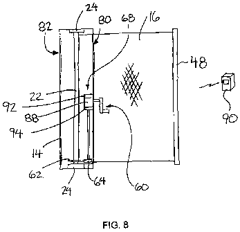
Figure 8 is a schematic elevational view of the second embodiment of
the gate system is a partially closed position spanning only partway across
the gate
opening as the fencing material is being wound onto the shaft of the housing.
In the drawings like characters of reference indicate corresponding parts
in the different figures.
DETAILED DESCRIPTION
Referring to the accompanying figures, there is illustrated a gate system
generally indicated by reference numeral 10. The gate system 10 is
particularly
suited for use in temporarily spanning a gate opening between two opposing
ends 12
defining the gate opening spanning in a vertical plane there between. The
opposing
ends 12 of the gate opening may comprise various forms of upright supporting
surfaces including walls, posts and the like.
The gate system 10 generally comprises a portable housing 14 which
CA 02782697 2012-06-01
WO 2011/066643 PCT/CA2010/001902
8
stores therein rolled up fencing material 16. The fencing material 16
generally
comprises an elongate sheet of flexible mesh material which is elongate in a
longitudinal direction between opposing first and second ends. The mesh
material
comprises interconnected strands of material in a pattern similar to
conventional chain
link fencing.
The housing 14 is elongate in an upright orientation in use spanning a
height corresponding approximately to a height of the sheet between opposing
longitudinally extending edges thereof. The housing extends in a respective
longitudinal direction between two end panels 18 at opposing ends thereof.
Each of
the end panels 18 is generally octagonal in shape such that the sides of the
housing
comprise eight side walls 20 interconnected in a generally octagonal cross
section so
as to span in the longitudinal direction between the two end panels 18. The
side walls
surround a hollow enclosure of the housing arranged to receive the fencing
material 16 therein in storage.
15 A shaft 22 is rotatably supported within the housing to extend in the
longitudinal direction thereof between the two opposed end panels 18. Suitable
bearings 24 at opposing ends of the shaft 22 support the shaft on the end
panels
respectively such that the shaft 22 is rotatable about a longitudinal axis
thereof which
is generally vertical in use.
20 The shaft 22 couples the first end of the fencing material 16 thereon
such that the shaft is oriented generally perpendicularly to the longitudinal
direction of
the sheet and the sheet is suitably arranged to be rolled onto the shaft when
the shaft
is rotated about its respective longitudinal axis. The shaft is centered in
the housing
an the housing is spaced outwardly from the shaft and surrounding the shaft
such that
the sheet can be fully rolled onto and wound about the shaft in the housing
when the
sheet comprises approximately 40 feet of fencing material in the longitudinal
direction
between the opposing first and second ends thereof.
The housing 14 includes an elongate slot 26 in the front side of the
CA 02782697 2012-06-01
WO 2011/066643 PCT/CA2010/001902
9
housing which spans the full length of the housing in the longitudinal
direction. The
slot 26 accordingly spans the height of the sheet of fencing material so that
the sheet
of fencing material can be received there through. Accordingly, the fencing
material is
arranged to be dispensed from a stored position in which the fencing material
is fully
wound onto the shaft and stored within the housing to a working position in
which the
fencing material is at least partially dispensed from the housing by being
unrolled from
the shaft to span across the gate opening.
The housing 14 includes a center mounting bar 28 and two end
mounting bars 30 supported on the rear side of the housing opposite the front
side
locating the slot 26 therein. The end mounting bars 30 are located adjacent
the
opposing ends of the housing and the center mounting bar 28 is centrally
located
there between. All three bars comprise a rigid member spanning perpendicularly
to
the longitudinal direction of the housing to extend laterally outward beyond
opposing
side edges of the rear side wall 20 supporting the mounting bars thereon such
that the
bars span in a lateral direction approximately a full width of the housing.
The end mounting bars 30 permit attachment of a wheeled base 32 onto
either end of the housing such that the wheeled base can be readily removed
therefrom and attached to the other end as may be desired. The wheeled base 32
generally comprises a frame arranged to span the end panel at one end of the
housing which includes a pair of retainers 34 mounted at the rear side for
selective
coupling onto opposing ends of the respective end mounting bar 30. A pair of
wheels
are supported at laterally spaced positions on the front side at the opposing
end of the
frame from the retainers 34.
The retainers 34 are arranged to be coupled to the mounting bars in a
manner which permits the housing to be tilted forwardly for rolling movement
onto the
pair of wheels 36 at the front side of the wheel base while the retainers 34
retain the
rear end of the frame of the wheel base 32 secured against the bottom end of
the
housing. Handles 38 are mounted externally on the side walls of the housing
which
CA 02782697 2012-06-01
WO 2011/066643 PCT/CA2010/001902
are arranged to be suitably grasped in the hand of a user so that the handles
38
together with the wheels permit the housing to be manually portable by
functioning as
a hand truck.
The center mounting bar 28 permits the housing to be selectively
5 mounted onto a first upright mount 40 mounted at one end 12 of the gate
opening.
The upright mount 40 is arranged to be secured to various forms of upright
supporting
surfaces. More particularly, the upright mount 40 comprises a rear panel 42
locating
fastener apertures therein permitting fasteners to be received there through
for
fastening the rear panel to the upright supporting surface at the end of the
gate
10 opening. The upright mount 40 further comprises two side flanges 44
supported at
laterally opposed side edges of the rear panel 42 to extend outwardly
therefrom at an
inclination such that the two side flanges project forwardly from the rear
panel with
increasing distance from one another towards respective forward edges. The two
side flanges 44 are arranged to receive the housing there between and serve to
guide
alignment of the housing with the rear panel 42 in a mounted position of the
housing
on the first upright mount 40.
Each of the two side flanges 44 comprised as an upper edge which is
sloped upwardly and inwardly at a suitable elevation for sliding engagement of
opposing ends of the center mounting bar 28 respectively thereon. A pair of
retainers
46 are mounted at the inner ends of the upper edges of the two side flanges 44
respectively. Each of the two retainers comprises a hook member which extends
forwardly and downwardly into overlapping engagement with the side flanges at
the
free end thereof so that the retainers may be hooked over top of the
respective ends
of the center mounting bar to retain the centre mounting bar fixed onto the
inner ends
of the upper edge of the two side flanges respectively.
The two retainers 46 are connected to a common horizontal pivot shaft
extending perpendicularly to the plane of the gate opening between the base of
the
two retainers 46 such that the two retainers are fixed for pivotal movement
together
CA 02782697 2012-06-01
WO 2011/066643 PCT/CA2010/001902
11
with one another and the pivot shaft spanning there between from a locked
position
extending over top of the ends of the center mounting bar to retain the center
mounting bar on the side flanges 44 and a release position in which the
retainers are
pivoted upwardly to be spaced above the side flanges at the free ends thereof
so that
the center mounting bar can be slidably disengaged from the upper edges of the
two
side flanges 44.
The forward edge of the two retainers 46 include respective cam faces
which are sloped downwardly and inwardly so that inward displacement of the
ends of
the center mounting bar in engagement with the leading edges of the retainers
46
cause the retainers to be automatically deflected upwardly from the locked
position to
a released position when coupling the housing onto the first upright mount. A
suitable
mechanism can permit the retainers 46 to be automatically deflected downwardly
into
the locked position once the center mounting bar reaches the inner ends of the
upper
edges of the two side flanges. A lock mechanism can be mounted on only one
side of
the first upright mount to retain both the retainers 46 in the locked position
as may be
desired.
The two retainers 46 of the upright mount thus comprise a first mating
connector and the center mounting bar comprises a second mating connector
arranged to be selectively engaged with one another in the mounted position of
the
housing such that the housing remains readily releasable from the upright
mount.
The hooked configuration of the first mating connector is arranged such that
the first
mating connector is restricted from being released from the second mating
connector
when tension is applied to the flexbile mesh fencing material spanning the
gate
opening which pulls the housing away from the upright mount 40 towards the
opposing end of the gate opening.
Furthermore, by restricting access to the mechanism to unwind the
fencing material and release the tension therefrom, the first mating connector
is
arranged to be restricted from being released from the second mating connector
by
CA 02782697 2012-06-01
WO 2011/066643 PCT/CA2010/001902
12
unauthorized persons from one or both sides of the fencing material spanning
the
gate opening.
The central location of the center bar 28 and the symmetrical
configuration of the two retainers 46 permits the housing to be readily
inverted
between two mounting positions which are flipped 180 degrees relative to one
another
about a central horizontal access the reversibility of the coupling of the
housing onto
the first upright mount allows accommodating differing mounting configurations
while
also permitting the user to select from which side of the gate in the working
position
access is restricted by unauthorized persons.
The central location of the center mounting bar 28 also permits levelling
of the housing about an axis of the center mounting bar which is generally
horizontal
and perpendicular to the plane of the gate opening. The gate in the working
position
can thus be levelled relative to the gate opening to ensure even tension
across the full
height of the fencing material in the working position.
The gate system further comprises an end bar 48 at the second end of
the fencing material in which the end bar 48 spans a full height of the
fencing material
between the opposing longitudinally extending edges thereof. The end bar 48
includes a plurality of vertically spaced apart retainer hooks 50 fixed
thereon. In the
illustrated embodiment a retainer hook 50 is provided at each of the opposed
ends of
the bar as well as at a central location there between. Each of the retainer
hooks
includes a first portion 52 extending in the longitudinal direction of the
fencing material
outwardly beyond the edge of the fencing material and a second portion 54
mounted
at the free end of the first portion. The second portion 54 is perpendicular
to the first
portion and spans laterally outward in two opposing directions therefrom to
outer ends
which are arranged to be hooked into respective sockets 56 of a second upright
mount 58.
The second upright mount 58 comprises a vertical member arranged to
be fastened to a upright supporting surface at the second end 12 of the gate
opening.
CA 02782697 2012-06-01
WO 2011/066643 PCT/CA2010/001902
13
Suitable fasteners for securing the second upright mount 58 to the upright
surface at
the second end of the gate opening may be hidden within a channel of the
vertical
member forming the second upright mount 58.
The sockets 56 are vertically spaced in the hollow channel member
forming the second upright mount so as to be aligned with the retainer hooks
50 of the
end bar. Each of the sockets is also T-shaped comprising a horizontal opening
forming an upper portion of the socket and a vertical opening forming a lower
portion
of the socket extending downward from a central location of the upper portion.
The
upper portion is arranged to receive the second portion of the retainer hooks
therein
while the vertical lower portion of the socket is narrower to correspond to
the width of
the first portion of the hooks so that the second portion is retained on
opposing sides
of the lower portion of the socket when the first portions of hooks are
slidably
displaced downwardly into the lower portions of the sockets. Inner protrusions
may
be provided within the socket which serve to prevent upward sliding of the
hooks 50
into released engagement from the sockets 56 when tension is applied to the
fencing
material of the gate.
In this instance, the sockets 56 in the second upright mount 58 comprise
first mating connectors while the hooks on the end bar comprise second mating
connectors arranged for mating engagement with the first mating connectors in
the
closed position of the gate system. By arranged the first and second mating
connectors at the second upright mount to also be restricted from being
released from
one another when tension is applied to the flexible mesh fencing material
spanning
the gate opening, both ends of the fencing material are prevented from being
released
from their respective end of the gate opening by unauthorized persons by
limiting
access to a winding mechanism 60 which controls tension on the fencing
material.
The winding mechanism 60 permits the fence material to be rolled up
from the working position to the stored position within the housing and also
permits
tension to be applied to the fending material spanning the gate opening in the
working
CA 02782697 2012-06-01
WO 2011/066643 PCT/CA2010/001902
14
position.
According to a first embodiment in Figures 1 through 3, the winding
mechanism includes a driven gear 62 supported about the shaft adjacent one end
thereof for meshing engagement with a drive gear 64 supported at the same end
of
the housing for rotation about a respective access which is parallel to and
spaced
outwardly from the shaft adjacent one of the side walls of the housing. A
drive shaft
66 is coupled for rotation with the drive gear and extends in a longitudinal
direction
parallel to the shaft along an inner side of one of the side walls for
connection to an
actuator 68 at a central location on the housing between the opposing ends
thereof.
Rotation of the actuator causes rotation of the drive shaft 66 which in turn
causes
rotation of the primary shaft 22 supporting the fencing material thereon
through
connection between the driven gear 62 and the drive gear 64. In this
embodiment a
crank handle 70 is mounted externally on the housing for connection to the
actuator
68 through a suitable internal gear box 72 in the housing manual rotation of
the
external crank handle 70 permits rotation of shaft 22 supporting the fencing
material
thereon in either direction for either rolling the fencing material onto the
shaft or
unrolling the fencing material from the shaft.
Turning now to the embodiment of Figures 6 through 8, the housing in
this instance is substantially identical to the previous embodiment, but
instead of
inverting top and bottom ends of the housing to reposition the handle 60
relative to the
dispensing slot in the housing, the housing according to Figures 6 through 8
is
arranged to dispense the fencing material from either one of two diametrically
opposed sides of the housing. Accordingly the housing in this instance
includes a first
dispensing slot 80 extending longitudinally along one side of the housing
parallel to
the shaft between the top and bottom ends of the housing, and a second
dispensing
slot 82 which is diametrically opposite to the first dispensing slot and which
similarly
extends in the longitudinal direction between the top and bottom ends,
parallel to the
shaft. The first dispensing slot dispenses the fencing material therethrough
in a first
CA 02782697 2012-06-01
WO 2011/066643 PCT/CA2010/001902
dispensing orientation shown in Figure 6 while the second dispensing slot
dispenses
the fencing material therethrough in a second dispensing orientation shown in
Figure
7.
The configuration of the retainers 46 forming the first mating connectors
5 on the first upright mount 40 are similar to the previous embodiment for
engaging
second mating connectors on the housing. The housing in this instance however
includes a first set of second mating connectors 84 diametrically opposite
from the
first slot 80 for mating with the first mating connectors 46 in the first
dispensing
orientation, and a second set of second mating connectors 86 diametrically
opposite
10 from the second slot 82 for mating with the first mating connectors 46 in
the second
dispensing position. In each instance, the first and second mating connectors
are
connected to remain engaged when tension is applied to the fencing material
and to
restrict release by unauthorised persons as described above with regard to the
previous embodiment.
15 The embodiment of 6 through 8 also differs from the previous
embodiment in that the actuator 68 comprises a suitable motor 88 which
includes
controls for operating the motor in a winding direction or operating the motor
in either
one of a winding or unwinding direction. The motor in the illustrated
embodiment
includes a remote controller 90 which is arranged to actuate operation of the
motor in
either the winding or unwinding directions. The remote controller 90 is suited
for
actuation by a user grasping the second end of the fencing material at a
location
spaced from the housing so that a single operator can support the fencing
material in
an upright orientation while operating the motor to displace the fencing
material
between working and stored positions as shown in Figure 8.
The actuator 68 in this instance is also arranged to accept insertion of a
handle 60 similar to the previous embodiment such that the manual crank handle
is
arranged to be selectively mounted externally on the housing in operable
connection
with the shaft for manually rotating the shaft relative to the housing, while
also being
CA 02782697 2012-06-01
WO 2011/066643 PCT/CA2010/001902
16
readily separable from the housing when operating the motor. The actuator 68
also
includes an appropriate motor shut-off switch 92 which is arranged to either
electrically or mechanically disconnect the motor. The switch 92 is engaged by
insertion of the manually operated handle 60 such that the switch is arranged
to
automatically disconnect the motor simply and automatically in response to
engaging
or mounting of the manual crank handle 60 onto the housing.
The motor 88 also includes a torque sensor 94 coupled thereto. The
torque sensor 94 is arranged to measure a torque of the motor corresponding to
tension of the flexible mesh fencing material spanning the gate opening. The
torque
sensor 94 is arranged to shut-off the motor when the measured torque exceeds a
prescribed torque limit to ensure the fencing material is automatically
tensioned to a
desired level with causing damage to any components of the gate system.
The housing also comprises a suitable brake operating on the shaft
which slows the unwinding of the shaft to maintain tension on the fencing
material as
the fencing material is drawn outwardly from the slot in the housing and is
unwound
from the shaft. The brake may also be operable using the remote controller
102.
In use, the first upright mount can be located in various locations
including upright walls in alley ways or upright walls along side a tunnel in
mines and
the like. In a mining application, suitable rock wall anchors may be provided
as
fasteners to fasten the first upright mount to the wall. As shown in figure 4,
an alcove
may be formed in the wall of a tunnel so that the housing may be fully
recessed into
the wall resulting in minimal obstruction in the tunnel when the fencing
material is in
the stored position. In yet further arrangements the first upright mount may
be
configured to anchor the two end mounting bars 30 instead of the centre
mounting
bar. Anchoring to the end mounting bars permits secure attachment to various
structures including the upright supporting surface of a mobile unit such as a
vehicle
as shown in the embodiment of figure 5.
In a typical use of the gate system 10 both the first upright mount 40 and
CA 02782697 2012-06-01
WO 2011/066643 PCT/CA2010/001902
17
the second upright mount 58 are fastened to respective opposing ends 12 of a
gate
opening across which fencing material is desired to be temporarily mounted.
The
user then mounts the housing onto the first upright mount 40 such that the
housing
can be readily separated therefrom and reattached thereto without requiring
any
fasteners to be attached or removed. Once the housing is mounted in place on
the
first upright mount, the fencing material is dispensed from the housing
towards the
working position spanning the gate opening so that the hooks at the end bar at
the
second end of the fencing material can be interlocked with the sockets 56 of
the
second upright mount. Subsequent tension applied to the fencing material of
the gate
using the actuator 68 retains the hooks 50 within the respective sockets 56.
The
actuator 68 can be locked in a position which maintains some tension on the
fencing
material. Access to the actuator can be restricted through an access panel on
the
housing which can be locked in a closed position to prevent access by
unauthorized
persons.
Since various modifications can be made in my invention as herein
above described, and many apparently widely different embodiments of same made
within the spirit and scope of the claims without department from such spirit
and
scope, it is intended that all matter contained in the accompanying
specification shall
be interpreted as illustrative only and not in a limiting sense.