Note : Les descriptions sont présentées dans la langue officielle dans laquelle elles ont été soumises.
CA 02788912 2012-09-07
Apparatus for the Transmission of Electromagnetic Waves
Field of the Invention
The present invention relates to an apparatus for the transmission of
electromagnetic
waves. In particular, it relates to an apparatus and a method which utilise a
reactive
surface which is suitable for Zenneck surface wave transmission.
Background to the Invention
The theory and use of electromagnetic surface waves has been well documented.
The term
"surface waves" covers a broad range of electromagnetic phenomena concerning
the
propagation of radio waves across a surface. Specifically, a surface wave is
one which
interacts with a surface in order that the wave propagates across that
surface. In the field of
radio transmission, the interaction between radio waves and the poorly
conductive surface
of the earth, is commonly referred to as surface wave propagation.
In the field of radio transmission, the use of surface waves to transmit radio
signals over
long distances, is well known. One of the characteristics of a surface wave,
which makes it
suitable for radio transmission, is the ability of the wave to "cling" to the
surface, and
therefore follow the curvature of the earth. This is in contrast to typical
electromagnetic
propagation, which generally propagates in a straight line.
Within the field of surface waves, there are a number of different
electromagnetic
phenomena which result in different types of surface waves. One phenomena by
which
radio waves propagate across the surface of the earth is known as the Norton
surface
wave. The Norton surface wave is the component of the electromagnetic field
close to the
homogeneous conducting ground when an electromagnetic wave is launched over
it. This
may be done, for example, by a dipole. The Norton surface wave requires a
space wave
component above the surface to exist. As noted above, there are a number of
technologies
that claim to utilise Norton surface waves for "over-the-horizon"
communications and
radar.
CA 02788912 2012-09-07
2
Summary of the Invention
In a first aspect, the present invention provides a system for the
transmission of
electromagnetic surface waves, the apparatus comprising: a guiding medium
having a first
surface, the first surface having an electrical reactive impedance suitable
for the
propagation of electromagnetic surface waves; at least two wave coupling
nodes, the
nodes each having a transmitter and/or receiver coupled to a transducer, the
transducer
positioned on or adjacent the first surface of said guiding medium; wherein
the at least two
wave coupling nodes arranged to launch and/or receive surface waves over the
first
surface of said guiding medium; wherein the wave coupling nodes may be placed
at
arbitrary locations on the first surface of the guiding medium.
In a second aspect, the present invention provides an article of clothing
incorporating the
system for the transmission of electromagnetic surface waves as described
above.
In a third aspect, the present invention provides an article of furniture
incorporating the
system for the transmission of electromagnetic surface waves as described
above.
In a fourth aspect, the present invention provides a building, vehicle or
other vessel
incorporating the system for the transmission of electromagnetic surface waves
as
described above.
In a fifth aspect, the present invention provides a wave coupling node
comprising: a
transmitter and/or receiver; a dielectric layer having first surface
constituting a first
surface of the node; a conductive layer, having a first surface positioned on
or adjacent a
second surface of the dielectric layer; a metallic plate, positioned on the
first surface of the
dielectric layer; and a feed line, coupling the transmitter and/or receiver to
the metallic
plate.
CA 02788912 2012-09-07
3
Brief description of the Drawings
The present invention will now be described by way of example only, with
reference to
the accompanying drawings in which:
Figure 1 shows an apparatus in accordance with a first embodiment of the
invention;
Figure 2 shows an apparatus in accordance with a second embodiment of the
invention;
Figure 3 shows a system in accordance with a third embodiment of the
invention;
Figure 4 shows an article of clothing in accordance with an embodiment of the
present
invention;
Figure 5 shows an article of furniture in accordance with an embodiment of the
present
invention;
Figure 6 shows an vehicle in an embodiment of the present invention; and
Figure 7 shows a corrugated conductor.
Detailed Description of Embodiments of the Invention
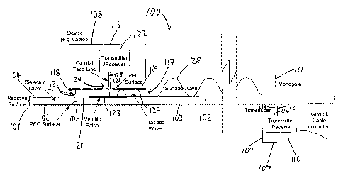
A first embodiment of the invention will be described in connection with
Figure 1. Figure
1 shows a radio frequency (RF) communication system 100. The communication
system
100 includes a guiding medium 101 which includes a dielectric layer 102 and a
conductive
layer 103. The dielectric layer 102 may take the form of a sheet of material
having a
uniform thickness. The width and length of the dielectric layer 102 may vary
depending
on the specific application. An upper surface 104 of the dielectric layer 102
is the surface
over which surface waves are transmitted, as will be described in more detail
below. The
conductive layer 103 may also take the form of a sheet of material having a
uniform
thickness. The width and length of the conductive layer 103 are generally the
same as
CA 02788912 2012-09-07
4
those equivalent dimensions of the dielectric layer 102. An upper surface 105
of the
conductive layer 103 is positioned against a lower surface 106 of the
dielectric layer 102.
The dielectric layer 102 and the conductive layer 103 accordingly form a
dielectric coated
conductor.
The upper surface 104 of the dielectric conductor 102, and hence the guiding
medium 101,
has a reactive impedance with is greater than its resistive impedance. Such a
surface is
suitable for guiding surface waves. In particular, the reactance and
resistance is such that
the surface is suitable for guiding Zenneck surface waves. The layer of air
formed above
the guiding medium acts as the transmission medium for the surface wave.
Further details
of the characteristics of the surface which make it suitable for guiding of
Zenneck surface
waves will be provided below.
The system 100 may also include two or more communications nodes. The nodes
are
arranged to communicate with each other using surface wave transmission, over
the
guiding medium 101. In the embodiment shown in Figure 1, the system includes a
fixed
communication node 107 and a moveable communication node 108. As an
alternative, the
system 100 may include two or more fixed communication nodes, two or more
moveable
communications nodes, or a combination of both types of communication node. A
moveable communications node is one which is not fixed in one place, and may
easily be
moved around the guiding medium 103.
The fixed communication node 107 includes fixed node main unit 109 which
houses the
primary components of the fixed communication node 107. The fixed node main
unit 109
is located on the opposite side of the conductive layer 103 to the dielectric
layer 102. The
fixed node main unit 109 may be attached to the lower surface of the guiding
medium, for
example using an adhesive. The fixed communication node 107 also includes a
transmitter/receiver 110 and a transducer 111. In the present case, the
transducer 111 is a
monopole antenna. The transmitter/receiver 110 is located within the fixed
node main unit
109. The transmitter/receiver 110 is coupled to the transducer 111 using a
coaxial feed
line 112. The coaxial cable 112 includes an outer conductor 113 and an inner
conductor
CA 02788912 2012-09-07
114. The outer conductor 113 is coupled directly to the conductive layer 103.
The inner
conductor 114 is coupled to the transducer 111.
At the point where the transducer 111 is coupled to the inner conductor 114,
the transducer
5 passes through the dielectric layer 102 and protrudes from the upper surface
104 of the
dielectric layer. The transducer 111 is perpendicular to the upper surface 104
of the
dielectric layer 102. The length of the portion of the inner conductor 114
which protrudes
from the dielectric layer 102 is less than a quarter wave length at the
operating frequency
of the system 100. The actual length will be dependent on the surface
impedance
produced by the guiding medium 103. Accordingly, the transmitter/receiver 110
is able to
transmit and receive signals via the monopole antenna 111. The fixed
communication
node 107 is coupled to an external communication device, such as a router, via
network
cable 115. The fixed communication node includes further circuitry (not shown)
which
enables the node to communicate with an external device, such as a router. The
fixed
communication node 107 also includes a modulator and a demodulator (not
shown). The
modulator is for modulating the transmitted signal with a signal received from
the external
device. The demodulator is for demodulating a signal received by the fixed
communication node 107.
The moveable communication node 108 may form part of a mobile computing device
such
as a laptop. The moveable communication node 108 may be formed as an integral
part a
mobile computing device, or may be connected thereto using a communications
cable or
other communications method. The moveable communication node 108 is shown in
Figure 1 having a moveable node main unit 116. The movable communication node
108
includes a moveable node transmission medium 117 which is located at a lower
end of the
moveable node 108. The node transmission medium 117 includes a dielectric
layer 118
and a conductive layer 119. The dielectric layer 118 is in the form of a sheet
of dielectric
material, having a similar uniform thickness to that of the dielectric layer
102. The extent
of the sheet of dielectric material is the same as that of the moveable main
unit 116. A
lower surface 120 of the dielectric layer 118 is exposed and is arranged to
come into close
contact with the upper surface 104 of the dielectric layer 102 of the guiding
medium 101.
CA 02788912 2012-09-07
6
An upper surface 121 of the dielectric layer 118 is covered in the layer of
conductive sheet
material 119.
The moveable node 108 includes a transmitter/receiver 122 and a metallic patch
antenna
123. The transmitter/receiver 122 is housed inside the moveable node main unit
116. The
transmitter/receiver 122 is coupled to the metallic plate 123 by a coaxial
feed line 124.
The coaxial feed line 124 includes an inner conductor 125 and an outer
conductor 126.
The metallic plate 123 is attached to a lower surface 120 of the dielectric
layer 118. The
inner conductor 125 of the coaxial feed line 124 passes through the dielectric
layer 118
and is coupled directly to the metallic plate 123. The outer conductor 126 is
coupled to the
conductive layer 119. In use, the dielectric layer 118 of the movable
communication node
108 is placed flat against the dielectric layer 102 of the guiding medium 101.
The operation of the system 100 will now be described. When the movable
communication node 108 is acting as a transmitter, the transmitter/receiver
122 sends a
modulated signal to the metallic plate 123. This causes a trapped
electromagnetic wave
127 to be formed within the dielectric layer 118 between the dielectric layer
102 and the
conductive surface 119. When this wave reaches the end of dielectric layer
118, it
propagates outwards. In particular, the electromagnetic wave forms a Zenneck
surface
wave 128 which travels across the surface of the guiding medium 101. In this
example,
the trapped wave 127 and the Zenneck surface wave 128 as shown for
representative
purposes only, and are not intended to be accurate representations of those
waves. The
Zenneck surface wave 128 propagates across the guiding medium in all
directions, and is
received by the transducer 111 of the fixed communication node 107. The
exposed inner
conductor 114 of the fixed communication node 107 is excited by the surface
wave 128.
The signal detected by the transducer 111 is received by the
transmitter/receiver 110.
Accordingly, the system utilises Zenneck surface waves to provide
communication
between different communication nodes across the guiding medium 101. Further
details
of the guiding medium and communications nodes will be provided below.
The system 100 may be deployed in a building or on furniture. For example,
walls and/or
desks may be covered in the guiding medium 101. A laptop or mobile phone may
be
CA 02788912 2012-09-07
7
coupled to a communication node in order to communicate with other devices or
a fixed
communication node. A laptop incorporating a communication node may be placed
anywhere on a desk covered with the guiding medium 101, and would be able to
communicate with other devices on the desk or with the fixed node 107. As
noted above,
the fixed node 104 may communicate with a central server. Alternatively, the
guiding
medium 101 may cover a wall which is covered in a magnetic surface. A
communication
node, also covered in a magnetic surface, may be attached to the wall. The
node may then
be coupled to a computing device using a cable connection (for example a
retractable
cable). Alternatively, the communication node could include a WiFi unit, and
could
communicate with local devices using WiFi. One of the benefits of this system
is that
wireless communications is provided across a wall, within a building, that
could not be
intercepted from the outside by a third party.
In another example, the system 200 may be deployed on a groundsheet for use in
a tent. A
table would also have the reactive surface applied to its top surface. The
legs of the table
would act as a communications link between the groundsheet and the table top.
For
example, a cable may run through the table legs, which may couple with fixed
communications nodes on the table top. At the bottom of the legs, the cable
may be
coupled to a communication node which is attached to the ground sheet using a
magnetic
layer, for example. An advantage of this system is that a communication
channel would
be provided through the tent that suitably equipped devices could communicate
through.
Again, this would provide wireless communications within the tent that could
not be
intercepted by third parties from the outside.
Figure 2 shows a second embodiment of the present invention. Figure 2 shows a
radio
communication system 200. The system 200 includes a guiding medium 201 which
has a
dielectric layer 202 and a conductive layer 203. The outer surface of the
dielectric layer
202 has a reactive surface. The system 200 also includes a hook-and-loop
fastener layer
204 which may, for example, be Velcro . The purpose of this layer is to
enable movable
communication nodes to be easily attached to the guiding medium 201.
CA 02788912 2012-09-07
8
The system 200 includes a first movable communication node 205. As will be
described in
the following, the movable communication node 205 is similar to the removable
communication node 108 shown in Figure 1. The node 205 includes a dielectric
layer 206
and a conductive layer 207. In addition, the node 205 includes a
transmitter/receiver 208
which is coupled to a metallic patch antenna 209 via a coaxial feed line 210.
The coaxial
feed line 210 has an inner conductor 211 and an outer conductor 212. These
components
are coupled in the same way as the corresponding components in removable node
108
shown in Figure 1.
The node 205 also includes a hook-and-loop fastener layer 213 which is
attached to the
node 205 over the outer surface of the dielectric layer 206 and the metallic
plate 209. In
use, the node 205 may be placed against the reactive surface 203 and will
adhere to that
surface by virtue of the hook-and-loop fastener layers. The node 205 may be an
RF
transponder which communicates with an external source using antenna 214.
The system 200 includes a second removable communication node 215 which may
incorporate a sensor. The node 215 includes a number of the same components as
the node
205. In particular, the node 215 includes a dielectric layer 216 and a
conductive layer 217.
The node 215 also includes a transmitter/receiver 218 which is coupled to a
metallic plate
219 via a coaxial feed line 220. The coaxial feed line 220 includes an inner
conductor 221
and an outer conductor 222. Finally, the node 215 includes a hook-and-loop
layer 223.
Operation of the system 200 will now be described. The node 215 may
incorporate a
sensor such as a heart rate monitor which provides data to the
transmitter/receiver 218 to
transmit information to the RF transponder 205. The transmitter/receiver 218
excites the
metallic plate 219 causing a trapped wave 224 to be formed in the dielectric
layer 216. At
the end of the dielectric layer 216 the trapped surface wave 224 causes a
surface wave 225
to be transmitted across the surface of the reactive surface 203. When the
surface wave
225 hits the dielectric layer 206 of the node 205, a trapped wave 226 is
formed in the
dielectric layer 206. This excites the metallic plate 209 which is received by
transmitter/receiver 208. This signal may then be transmitted via the antenna
214 to an
external source.
CA 02788912 2012-09-07
9
In the second embodiment, the dielectric layer 201 and the conductive layer
202 may be
deformable. For example, the conductive layer may be a woven conductive mesh,
and the
dielectric layer may be neoprene. These layers may form part of an article of
clothing.
The communications nodes may be relocated at arbitrary positions on the
surface of the
reactive surface. One of the advantages of this arrangement is that the
guiding medium is
not, and does not require to be modified by the communications nodes. A more
comfortable layer can be placed on the conductive layer against the users
skin.
As noted above, the communication node 215 may include a sensor. In one
embodiment,
the system 200 may include a number of communications nodes, each having its
own
sensor. These sensors may be positioned across the body to measure parameters
like heart
rate and blood pressure. The system can therefore be used to monitor the
health of a
patient, fire-fighter or athlete. The sensors communicate with the central
communication
node 205. The central node relays this data back to a central database via
antenna 214. On
of the benefits of this system is that there are no wires to restrict movement
and devices
can be added or removed arbitrarily.
The system 200 of the second embodiment may also include sensors which monitor
an
external device. For example, the external device may be a motorbike. Sensors
on the
bike measure the amount of fuel remaining in the petrol tank, tire pressures,
engine
temperature etc. These sensors are coupled to a communication node which may
be
attached to the clothing of the rider, which incorporates the system 200. In
addition, the
rider's helmet may include a heads-up display which is also coupled to a
communication
node on the rider's clothing. The sensors and heads-up display would
communicate with
each other so that the data collected by the sensors is displayed on the heads-
up-display.
In addition, the sensors relay their data to the central node 205 so that the
data can be sent
back to a base. Again, an advantage of this system is that it is wireless, so
there are no
wires to snag. Furthermore, as there are no connectors, there is no need to
worry about
connecting connectors or connectors becoming disconnected. Again, the devices
can be
repositioned at arbitrary locations across the item of clothing. Another
advantage of the
CA 02788912 2012-09-07
system is that communications channel is close to the body, reducing
interference with
adjacent systems and minimising the chance of detection by a third party.
Current solutions use either wired or radiating mechanisms to communicate
signals around
5 the body. Wired systems can break and snag on things in the environment.
They also
have bulky connectors and limit where devices can be placed on the body.
Radiated
systems have difficulty with non line-of-sight connections, particularly at
high frequencies
(for example above 10GHz) required for high bandwidths. These radiated systems
can
also be intercepted and can suffer from interference. The system of the
present invention
10 address all of these problems.
On of the advantages of the system 200 is that Zenneck waves travel along the
surface,
even when the surface is not flat. This enables flexible positioning of
devices, for example
out of line-of-sight, without the use of connectors. The system does not
include wires
which may snag on things in the environment. Furthermore, it provides a
secure, reliable
data-link, that is effectively immune to interference.
In the above embodiments, transducers which are radial waveguides have been
described.
The system may use patch antennas, monopole antennas or dipole antennas as
transducers.
The antenna must be aligned for its polarisation to match the polarisation of
the surface
wave being transmitted/received. The distance that the transducer needs to be
from the
reactive surface varies according to the application. For example, the
thickness of the
dielectric forming the surface and the frequency of transmission affect the
position of the
transducer.
Figure 3 is a schematic diagram of a radio frequency (RF) communication system
in
accordance with a third embodiment of the present invention. Figure 3 shows a
radio
frequency (RF) communication system 300. The communication system 300 includes
a
surface wave guiding medium 301 which includes a dielectric layer and a
conductive
layer. The system 300 also includes a transmitter unit 302 and a receiver unit
303. In
practice, the transmitter unit 302 may also act as receiver unit, and the
receiver unit 303
may also act as a transmitter unit.
CA 02788912 2012-09-07
The transmitter unit 302 includes a laptop computer 304 which has an HDMI
output port
305. The laptop computer 304 acts as a source of signals to be sent over the
surface wave
material 301. The transmitter unit 302 also includes an HDMI to SDI converter
306. The
HDMI to SDI converter 306 includes an HDMI input port 307 and an SDI output
port 308.
The HDMI output port 305 of the laptop 304 is coupled to the HDMI input port
307 of the
HDMI to SDI converter 306 via cable 309. The transmitter unit 302 also
includes a 60GHz
transmitter 310. The 60GHz transmitter 310 may for example be a Vubic TX300.
The
60GHz transmitter 310 includes a wireless HD core 311, a transmission
amplifier 312 and
a flange 313 suitable for coupling to a waveguide. SDI output port 308 is
coupled to the
wireless HD core 311 via cable 314. The transmitter unit 302 also includes a
battery pack
315 which provides a 12v power supply to the HDMI to SDI converter 306 and the
60GHz
transmitter 310. The transmitter unit 302 also includes a 60GHz launcher 316.
The 60GHz
transmitter 310 is coupled to the 60GHz launcher 316 via a waveguide 317. The
60GHz
launcher 316 is coupled to the surface wave material 301.
The receiver unit 303 includes a set of components which correspond to those
of the
transmitter unit 302. The receiver unit 303 includes a 60GHz launcher 318
which is
coupled to the surface wave material 301. The receiver unit 303 includes a
60GHz receiver
319 which includes a waveguide coupling flange 320, a receiving amplifier 321
and a
wireless HD core 322. The receiver unit 303 also includes a waveguide 323
which is
coupled between the 60GHz launcher 318 and the flange 320. The receiver unit
303 also
includes an HDMI to SDI converter 324 which includes an SDI input port 325 and
an
HDMI output port 326. The wireless HD core 322 is coupled to the SDI input
port 325 by
cable 327. The receiver unit 303 also includes a battery pack 328 which
provides a 12v
power supply to the 60GHz receiver 319 and the HDMI to SDI converter 324. The
receiver unit 303 also includes a laptop computer 329 which includes an HDMI
input port
330. The HDMI output port 326 and the HDMI input port 330 are coupled together
by
cable 331.
In operation, the laptop 304 transmits a signal to the HDMI to SDI converter
which is
converted to SDI before being forwarded to the 60GHz transmitter. From here
the signal is
CA 02788912 2012-09-07
12
transmitted to the 60GHz launcher 316 where a surface wave is generated on the
surface
wave material 301 as described above in connection with figures 1 and 2. The
surface
wave is received by the 60GHz launcher 318 where it is transmitted to the
60GHz receiver
319. From here the signal is converted to HDMI via the HDMI to SDI converter
324
before being forwarded to the laptop computer 329.
Figure 4 shows a system in accordance with the present invention in which the
invention is
incorporated within an article of clothing 400. The article of clothing 400 is
made of a
material which is suitable for carrying surface waves. The system includes
various
components including a backpack 401, a radio phone 402, a blood pressure
monitor 403, a
heart rate monitor 404 and a handheld device 405. Each of these components
includes all
of the necessary components to launch a surface wave onto the clothing item
400. As can
be seen, the various components may communicate with each other over the
surface of the
item of clothing. To be clear, the hash line shown between the various
components
represent surface waves rather than cables or other wiring.
Figure 5 is an embodiment of the present invention in which the system is
implemented on
an item of furniture 500 and a wall 501. The item of furniture 500 and the
wall 501 are
covered in a reactive surface suitable for surface wave transmission. This is
shown as the
surface wave channel 502 and 503. As can be seen, various components placed on
the
table may communicate with each other and to a network or other devices via a
surface
wave channel.
Figure 6 shows an embodiment of a present invention in which the system is
implemented
in a vehicle, in this case an aircraft. In this case, a surface wave channel
600 is placed
along the wall of the aircraft 601. As can be seen, an entertainment system
602 on the rear
of each seat 603 has arranged to communicate with a central system via the
surface wave
channel 601.
Further details of the guiding medium introduced above will now be provided.
In the
above embodiments, the method of transmission is via Zenneck Waves or H-
Surface
waves (magnetic analog of Zenneck Waves that are polarised parallel to the
surface). The
CA 02788912 2012-09-07
13
system described above is designed to utilise Zenneck surface wave propagation
for RF
transmission applications. Conventional RF transmission is unguided in three
dimensions
through free space or guided in one dimension using conductors. The Zenneck
surface
wave is unusual in that it can be guided in two dimensions using a carefully
designed
surface. Before describing some of the physical parameters of the guiding
medium
introduced above, it is important to distinguish between the different types
of surface
waves which are collectively referred to as "surface waves".
Norton surface waves have been mentioned above. The Norton surface wave is
simply the
component of electromagnetic field close to a homogeneous conducting ground
when an
electromagnetic field is launched over it, for example, by a dipole. The
Norton surface
wave requires the space wave component above the surface to exist. There are a
number of
technologies that claim to utilise surface waves for "over-the-horizon"
detection and
communications. These are utilising the Norton surface wave.
Creeping waves are waves that appear to "creep" around corners such as around
the
surface of a metallic cylinder or sphere. These waves are a result of the
diffraction of the
space wave around the obstacle.
Trapped surface waves occur in dielectric materials when the wave is launched
into the
dielectric. Total internal reflection of the wave prevents it from escaping.
This means that
the wave can be guided inside the dielectric to another point where the
geometry of the
guiding structure allows it to escape, in a similar manner to the way in which
optical fibres
function.
Zenneck surface waves are self-supporting electromagnetic fields that
propagates over a
high reactance surface (inductive or capacitive). It propagates parallel to
the surface with
the field decaying exponentially perpendicular to the surface. How quickly it
decay away
from the surface is determined by the surface reactance. It is this wave that
is utilised in
this invention.
CA 02788912 2012-09-07
14
The Zenneck surface wave can be supported by a number of surfaces, including a
corrugated conductive surface, a conductive surface coated with a layer of
dielectric or a
metamaterial such as the Sievenpiper high impedance surface. A suitable
transducer, such
as the monopole antenna noted above, may be arranged to launch a surface wave
over the
surface. That wave can be intercepted by another transducer.
One of the advantages of using surfaces which are able to sustain Zenneck
waves, is that a
Zenneck wave can remain open to free space. In order to cause a normal
electromagnetic
wave to propagate along a surface, a pair of parallel plates can be used,
which act as a 2D
waveguide with the trapped wave propagating between them. However, any nodes
would
have to be located between the plates. This would mean having holes where the
data cable
exits the plates or having the nodes at the edges of the plates. If the plates
were replaced
by a mesh, there would still be the complexity of separating the mesh with
dielectric and
then introducing a node. This would deform the dielectric or require holes to
be fixed
therein. By contrast, the Zenneck surface wave is open to free space, allowing
nodes to be
added easily. The nodes do not even need to be in direct contact with the
surface
(although they should be close to it).
One of the advantages of a system utilising Zenneck waves, is that they are
bound to the
surface and do not radiate away from the surface. Accordingly, Zenneck waves
do not
interfere with traditional wireless communications. As the frequency spectrum
is
currently heavily loaded with a limit on the bandwidth allowed for
communications, any
system which does not interfere with traditional communications system is
advantageous.
Another advantage of Zenneck waves is that they can provide a large bandwidth
and high
data rates at microwave frequencies.
In order for the systems described above to utilise Zenneck waves, a channel
for
propagation of the Zenneck wave in E or H modes must be provided. The channel
creates
an artificial surface impedance and need not be flat or straight. In the above
examples, we
have described the use of a dielectric layer and conductive layer combination.
However,
other embodiments are possible, as will be described in the following. Here,
three primary
CA 02788912 2012-09-07
guiding mediums are described: a dielectric-coated conductor (as described
above),
corrugated conductor (with or without a dielectric coating) and the
Sievenpiper high
impedance surface.
5 It has been found that that a surface reactance of approximately 50 Ohms to
1000 Ohms is
optimum for transmission of Zenneck waves, if a wide bandwidth is required.
Any suitable
dielectric can be used for this purpose. For example, a 3mm thick layer of
neoprene
backed with aluminium foil could be used for clothing applications at around
30GHz. The
resistance of the surface should as low as possible. In the case of a
dielectric coated
10 conductor, the dielectric should be low loss and the conductor should have
as high a
conductivity as possible (such as copper or aluminium). Low loss usually means
having a
high air content. However, this must be balanced against the relative
dielectric constant,
which needs to be high to make the material thinner, whereas air has a low
dielectric
constant. Many plastics such as PTFE would be potential candidates depending
on the
15 application. A reactance outside of this band can still support a Zenneck
surface wave, but
at lower bandwidths.
A dielectric coated conductor can be designed using the following equation:
Z' 1 a)Juo0 + wuo ~r -1 l + 1 t\
2 el 2
where Zs is the surface impedance, w is the angular frequency, o is the
permeability of
free space, A is skin depth of conductor (conductor depth should be greater
than the skin
depth), Cr is relative permittivity of the dielectric and 1 is depth of
dielectric.
The surface impedance of corrugated conductor is given by the following
equation:
Zs = RS # jZ,,F ()tan ( )
where, Zs is the surface impedance, Rs is the surface resistance (normally
close to zero for
a good conductor), Zw is the characteristic wave impedance for groove (i.e.
377 Ohms for
air, varies for different dielectric coatings), d is the width of a trough (d
< h), h is the
height of trough and D is the width of trough plus width of ridge (3D < X).
CA 02788912 2012-09-07
16
Careful consideration must be given to the choice of d, D and h as the
mechanical
tolerances associated with these varies for different combinations. Having d
and h as
similar as possible may provide better tolerance specifications.
Figure 7 shows an example of a corrugated surface 700. The surface includes a
series of
parallel grooves 701. The surface allows Zenneck wave propagation in a
direction
perpendicular to the grooves. The structure can be metallic (copper or
aluminium) or can
be a lighter/more flexible material where the corrugated surface is coated in
a conductor
(e.g. some form of metallic paint). Example parameters would be h=1.04mm,
d=1.04mm
and D=1.5mm which provides an effective surface for Zenneck wave propagation
at
around 30GHz.
For efficient coupling into the reactive surface, the field in the aperture of
the coupler
should ideally match the exponential decay rate of the surface wave field away
from the
surface. For a uniform aperture, its vertical extent should be no larger than
the extent of
the wave above the surface (where the power has dropped by around 20dB from
the
surface). For example, at 23GHz with Xs of around 150 Ohms, the extent of the
wave
above the channel is around 1 cm. The transducer aperture should therefore be
as close to
the surface as possible and have a vertical extent of no greater than 1 cm.
Where possible,
the coupler should be matched to the surface for maximum power transfer. Two
couplers
that have proven to be effective are a monopole and a waveguide transition.
Other
possibilities are dipoles, patches and arrays.
There are various advantages of the dielectric channel described above.
Spreading of
waves is primarily in two dimensions across the surface. The surface is low
loss when
compared to other wireless alternatives (for example, around 2dB/m at 23GHz).
Because
the waves follow the reactive surface, physical non-line-of-sight
communication is
possible.
CA 02788912 2012-09-07
17
In the examples given above, communications between two nodes has been
described. As
communications nodes may be placed anywhere on the guiding medium, multi-node
to
multi-node connections are possible.
The systems described above may use very high bandwidths. For example, 23 to
33GHz
have been demonstrated. The systems described above may operate in a wide
range of
frequency bands. Zenneck waves demonstrate a high attenuation rate away from
the
surface. The attenuation is exponential. For example, 17dB/cm at 23GHz has
been
measured. The channel does not need not be continuous. The Zenneck wave can
transform to a space wave and can then re-couple to the surface at a later
point.
The selection of the communication channel will depend on the targeted
application. The
following guidelines can be used:
Requirement Example channel choice
Flexibility Dielectric coated conductor
Light weight Dielectric coated conductor
Rigidity Corrugated conductor
Higher frequencies (>10GHz) Corrugated conductor or
dielectric coated conductor
Retro-fitting Dielectric coated conductor
Multi-direction signals Dielectric coated conductor
Single direction signals Corrugated conductor
For example, for the body centric networking example given above, a dielectric
coated
conductor is the preferred choice as a flexible dielectric layer can easily be
incorporated
into clothing.
The system could be used for communicating through pipes or wells. Here, a
dielectric
coating or corrugated conductor could be applied to the pipe wall. For high
capacity
wireless transmission of data over small and large electrical distances, a
dielectric coated
conductor, corrugations, or lumped inductances and capacitances could be used.
For
CA 02788912 2012-09-07
18
secure wireless transmission of data (e.g. machinery, in buildings, over
ground sheets,
over furniture, etc.), a dielectric coated conductor, corrugations, or lumped
inductances
and capacitances could be used.
Using the above described systems, various modes of networking are possible.
For
example, point-to-point, point-to-multi-point, multi-point-to-point, and multi-
point-to-
multi-point are all possible. The designed surface wave can have duel wide
bandwidth
(wide bandwidth at two centre frequencies utilising the said designed surface
by changing
polarisation of couplers). In this document the term "surface wave"
specifically refers to
electromagnetic phenomena rather than, for example, optical or mechanical
phenomena.
In contrast to the other surface waves, Zenneck surface waves are not used for
long
distance communication as they require a high impedance reactive surface to
propagate
effectively. These surfaces do not exist naturally but can be constructed.
These waves are
the most efficient at propagating as they do not have a radiating component to
lose energy.
Power Transmission
The systems described above may also be used for power transfer. For example,
a
charging matt could be used to charge a device using the principles described
above. Such
a system may include a matt, the top layer of which includes a guiding medium
such as
those described above in connection with Figures 1 and 2. The system may also
include a
charging unit, which is a similar unit to those described above in connection
with Figures
I and 2, except the unit's purpose is to emit an electromagnetic wave for the
purposes of
power transfer. The system also includes a unit to be charged. For example
this could be
a cellular mobile device. This unit is placed on the matt and received the
electromagnetic
wave from the charging unit, thereby charging the device.
Sensing and Radar
The systems described above may also be used for sensing applications. For
example, the
system could be used in security applications to determine if an article is
placed on a
CA 02788912 2012-09-07
19
surface which is formed from the guiding medium noted above. A sensing unit is
arranged to transmit a Zenneck wave across the surface. In the absence of any
reflections
of that wave, the sensor determines that no articles have been placed on the
surface. If an
article (such as an intruder, or an object placed by an intruder) is placed on
the surface, the
Zenneck wave is reflected back to the sensing unit, which detects the
reflected wave. The
sensing unit may then sound an alarm.