Note : Les descriptions sont présentées dans la langue officielle dans laquelle elles ont été soumises.
CA 02790545 2012-09-18
- 1 -
METHOD FOR LOAD REGULATION OF AN AMMONIA PLANT
DESCRIPTION
Field of the invention
The present invention relates to production of ammonia. The invention relates
to
a method for regulation of an ammonia plant. The invention also relates to a
process and plant which implement the method for a flexible production of
ammonia.
Prior Art
Synthesis of ammonia starting from hydrogen and nitrogen is known. According
to the known art, a make-up gas comprising hydrogen and nitrogen is
catalytically converted to ammonia in a high-pressure (HP) synthesis loop,
usually at a pressure around 80 ¨ 300 bar. This make-up syngas is produced in
a front-end section, where hydrogen is produced by steam reforming of a
hydrocarbon source. The hydrocarbon source is natural gas or a synthesis gas
produced by partial oxidation of another carbon source, e.g. gasification of
coal.
The nitrogen source is usually air; in some embodiments nitrogen is delivered
by an air separation unit (ASU).
A known set-up for example includes the following steps. A desulphurized
hydrocarbon feed is reformed with steam in a primary reformer, obtaining a
first
gas product containing CO, CO2 and H2 at a temperature around 800 C; said
first gas product is reacted with air, enriched air or oxygen in a secondary
reformer or auto-thermal reformer (ATR), obtaining a second gas product at
around 1000 C; said second gas product is treated to remove impurities in a
section including a shift converter, a CO2-removal unit and a methanator. The
so obtained make-up syngas is fed to the HP synthesis loop via a main
compression section, usually comprising a multi-stage compressor.
CA 02790545 2012-09-18
= - 2 -
In use, a purge stream is continuously drawn from the HP loop, to remove
inerts
that would otherwise accumulate in the reactor and affect the overall
efficiency.
The term inerts is used to denote gases which are inevitably contained in the
make-up syngas but inert to the catalytic reaction of conversion, for example
Argon. The purge gas stream contains also some hydrogen that can be
separated and recycled to the loop. The purge rate is regulated in order to
maintain a low concentration of said inerts in the overall loop circuit,
typically
less than 10% molar.
A conventional ammonia production process according to the above is
disclosed for example in US 4,383,982.
The above process, using steam reforming of a hydrocarbon as the hydrogen
source, is well suited for large ammonia plants. A large ammonia pant is
usually
planned to operate continuously, and price and availability of the hydrocarbon
source are generally stable and do not experience significant changes in the
short term. This means that the hydrogen feed of a large, steam-reforming
based ammonia plant is relatively stable, and the plant operates constantly at
full capacity or near full capacity.
There is however a growing interest to a more flexible production of ammonia,
especially on a smaller scale. A flexible production of ammonia is desirable,
in
particular, where the hydrogen source is the electrolysis of water.
Electrolysis-
based ammonia is particularly attractive for small-scale and distributed
ammonia production. Small-scale ammonia production is emerging for many
applications including: production of fertilizers at remote locations; on-site
production of ammonium hydroxide (known as ammonia solution or aqua-
ammonia) for example directly in a power plant or waste incinerator;
distributed
production of ammonia for use as a fuel.
Using electrolysis of water to produce hydrogen means that electric energy is
the ultimate source of hydrogen. Availability and/or price of electric energy
is
CA 02790545 2012-09-18
- 3 -
typically subject to short-term fluctuations, on a daily or hourly basis,
which
means that a more flexible ammonia plant is desirable to follow the
fluctuation
of the availability and/or cost of the energy and, then, of the hydrogen feed.
It
could be desirable for example to produce ammonia when the cost of the
energy is lower, and reduce the capacity of the ammonia plant to a minimum,
when the cost of energy is higher. This is even more true when the electric
energy is produced with a renewable source, such as solar or wind.
The ammonia synthesis reactor, however, cannot operate at the nominal
elevated pressure (100 - 500 bar) when make-up gas feed falls below a
minimum flow rate. Catalyst would be in excess over the make-up gas, and the
temperature of the reaction would increase in a dangerous manner. The
minimum flow rate to keep the reactor safe is usually at least 50% of the
nominal flow rate. Overheating can be prevented by reducing the pressure of
the synthesis loop when operating at partial load, in order to slow down the
chemical reaction. But this would introduce another drawback, because the
reactor vessel would suffer fatigue stress due to frequent pressurization and
depressurization. Another problem is that the operation of the synthesis loop
at
a partial load is much less efficient compared to operation at full capacity
and,
as a consequence, the specific consumption is much higher.
These drawback are of a minor importance in large ammonia plants, which are
in any case unable to operate below a 50% - 60% of nominal capacity, due to
minimum turn down of the front end and because there would be no incentive to
run such a large plant at a low partial load. The same drawbacks however are
an obstacle to the implementation of small-scale ammonia production based on
electrolysis of water instead of steam reforming, where it could be necessary
or
desirable to turn down the ammonia production to a low partial load, well
below
50%. As stated above, regulation of the synthesis pressure is not a
satisfactory
solution for the risk of a fatigue failure of the reactor; another solution
could be
given by providing several ammonia production lines in parallel, each line
CA 02790545 2012-09-18
- 4 -
having its own make-up gas compressor and high-pressure loop, but this would
increase the capital cost and is generally not acceptable. Hence the prior art
does not provide a solution to the above problem.
Adaptation of the synthesis loop at low partial loads is desirable as well
with a
front-end of a different nature, e.g. autothermal reformer (ATR), partial
oxidation
(PDX) or a small-scale reformer (mini-reformer), i.e. in all those cases where
it
would be convenient to operate the loop well below its nominal capacity. In
such
a case the same problems above (risk of reactor overheating, low efficiency,
fatigue stress if pressure is reduced) are encountered.
Summary of the invention
The aim of the invention is to overcome the above problem by providing a
flexible ammonia process. One of the aims of the invention is to provide an
ammonia process whose output can be regulated to follow short-term variations
of cost and/or availability of a source feed, in particular of hydrogen
produced
by electrolysis of water.
The basic idea of the invention is to operate the ammonia synthesis loop at
the
nominal synthesis pressure, even at a partial load, while compensating for the
lower gas feed by increasing the concentration of argon and other inerts in
the
synthesis loop, and particularly in the reactor. Said inerts will dilute the
reagent
and product gas in the reactor, thus protecting the reactor from overheating.
Hence the invention provides a method for regulation of an ammonia plant, said
ammonia plant comprising a high-pressure ammonia synthesis loop comprising
at least an ammonia reactor, where a make-up gas comprising a hydrogen feed
and a nitrogen feed is converted into ammonia at a synthesis pressure; said
loop also comprising a purge line arranged to draw a flow of a purge gas
containing inerts from said loop, said method being characterized in that:
= during operation of the ammonia plant at a partial load, the ammonia
CA 02790545 2012-09-18
- 5 -
synthesis loop is operated at said synthesis pressure, and said purge flow is
reduced obtaining a concentration of inerts in the ammonia synthesis loop
which is greater than concentration of inerts in the loop at nominal load.
The partial load is understood as a condition where the ammonia output (kg/s
or
tons per hour) is less than a nominal capacity. The partial load is denoted
with
indication of the actual ammonia output as a percentage of the nominal
capacity.
Preferably, the. method includes the step of regulating the purge flow rate in
order to keep a substantially constant temperature in the ammonia reactor. In
some embodiments, the purge flow rate is regulated as a function of the
temperature in a selected point of the loop, e.g. inside the ammonia reactor.
The above method can be carried out by regulating the opening angle of a
purge flow controlling valve. Said valve can be installed on the purge line.
The amount of purge gas extracted from the loop can be determined as a
fraction of the make-up gas. At a nominal load, the molar flow rate of the
purge
gas is typically a few percent of the molar flow rate of make-up gas. The
ratio
between the flow rate of said purge gas and the flow rate of make-up gas is
less
than nominal, when the ammonia plant is operated at a partial load.
According to a preferred embodiment, said ratio is adjustable until it reaches
50% or less of the nominal value, when the ammonia plant is operated at a
minimum load. More preferably, said ratio is adjustable until a value which is
two to four times smaller than the nominal one. The minimum load is preferably
less than 20% and may reach around 10% in some embodiments.
In some embodiments of the invention, the purge rate can be reduced until the
concentration (in volume) of inerts in the synthesis loop reaches 40 ¨ 70 %
and
preferably around 50%, which is around 5 times the normal concentration.
The minimum achievable load may vary but in some embodiments of the
CA 02790545 2012-09-18
- 6 - invention, as stated above, the minimum load achieves 10% - 20%, i.e.
ammonia output equal to 10% - 20% of nominal capacity. Preferably the above
values of concentration of inerts (40 to 70%) are adopted when the ammonia
plant runs at low partial loads such as 10 to 20%. In some embodiments, the
amount of inerts accumulated in the loop is substantially proportional to the
partial load, i.e. can be determined with a linear proportion.
According to a particularly preferred embodiment, said plant comprises a water
electrolysis section and said hydrogen feed is produced by electrolysis of
water.
Then, the ammonia production is regulated by reducing or increasing the load
of
said electrolysis section, and reducing or increasing the flow rate of the
nitrogen
feed accordingly. According to a preferred embodiment, the nitrogen feed is
generated by separation of air.
Said purge gas contains gases which are inert to the synthesis reaction.
Usually
a large part of said inert gases is given by Argon; in some embodiments the
purge rate may also contain hydrogen and/or nitrogen, if the make-up gas
contains hydrogen and/or nitrogen in excess compared to the stoichiometric
rate (3:1) for conversion into ammonia (NH3). The nature and amount of the
inert gases may vary. For example if the hydrogen feed is produced by
reforming of natural gas, the inerts found in the synthesis loop may include
some unconverted methane and further gases depending on composition of the
natural gas. For example in some cases the inerts may comprise a certain
amount of Helium. It should be noted that the term of inerts, in this
description,
is referred to the synthesis of ammonia and then the "inerts" in the loop may
include the known inert gases (Argon, Helium) and substances (water,
methane) which do not take part to the conversion, thus being substantially
"inert" relative to the synthesis of ammonia. Excess nitrogen and/or nitrogen
are
also considered inerts.
The main advantage of the invention is that the ammonia plant can be operated
CA 02790545 2012-09-18
- 7 - at a partial load keeping a good efficiency and protecting the reactor
from
overheating. The ammonia plant can follow a time-varying availability and/or
price of a source feed such as electric energy and/or water in embodiments
with
electrolysis-based front end. This is possible even on a short-term basis,
such
as daily or hourly.
Referring more in detail to embodiments where the hydrogen feed comes from
electrolysis of water, the ammonia plant can be operated at full nominal load
(100%) when the full electric power is available and/or the energy is cheaper,
and can be operated at a reduced load less than 50% when less power is
available and/or price is higher. The same is applicable to availability or
cost of
water. This means that the electrolysis-based ammonia production becomes
more attractive from an economical point of view.
Hence, electrolysis-based ammonia plant can be efficiently powered by
renewable energy sources such as solar or wind. The load of the ammonia
plant can be regulated in a flexible manner, for adaptation to the
fluctuations of
the power output provided by renewable energy sources. Hence, for example,
an ammonia plant can be partly or fully powered by a.solar or wind power
plant,
leading to a virtually carbon-free ammonia production. This option is
attractive
especially for small-scale ammonia production in a remote site or for
agricultural
use, where ammonia can be produced on-site without the need of a
hydrocarbon feed.
A small-scale ammonia plant is understood as a plant with a nominal capacity
of
less than 50 tons per day of ammonia.
The invention can also be used to regulate the load of the ammonia plant
following the price of energy, either produced with a conventional or
renewable
source. For example when price of energy is higher it could be preferred to
turn
down the ammonia plant, or to sell directly the energy whenever applicable;
when the price is lower it could be preferred to use the energy for powering
the
CA 02790545 2012-09-18
- 8
electrolysis unit and hence to produce ammonia.
It has been found that by raising the concentration of inert in the loop the
efficiency at partial loads remains surprisingly good. For example an ammonia
plant operated at a 10% load, according to the invention, has a specific
consumption of electric energy (kWh per kg of ammonia output) which is only
¨ 15 % higher than specific consumption at nominal capacity. For a
comparison, specific consumption of a conventional large ammonia plant is
almost doubled when passing from nominal capacity to 50% partial load.
The same or similar advantages are achieved with different front-ends such as
10 ATR, PDX, etc.
Other aspects of the invention are a related process and plant for the
production
of ammonia.
The advantages of the invention will be elucidated with the help of the
following
description of preferred and non-limiting embodiments.
Brief description of the drawings
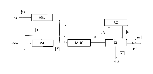
Fig. 1 is a block diagram showing a plant for production of ammonia with
generation of hydrogen by means of electrolysis of water, according to a
preferred embodiment of the invention.
Detailed description of a preferred embodiment
Referring to Fig. 1, block WE denotes a water electrolysis unit fed with water
feed 2 and electric power 1. Said unit WE deliver a current 3 composed mainly
of hydrogen, which is mixed with a current 4 composed mainly of nitrogen, to
form a make-up gas 5.
The process of electrolysis, which takes place in the unit WE, is known and
not
further described. The nitrogen current 4 is preferably obtained by separation
CA 02790545 2012-09-18
- 9 - ,
from an air flow 12, more preferably with a technique chosen between:
molecular sieves; pressure swing adsorption (PSA); vacuum pressure swing
adsorption (VPSA); temperature swing adsorption (TSA); a process based on
membranes; a process of cryogenic separation.
The make-up gas 5 is compressed to a synthesis pressure, preferably in the
range 80 to 500 bar, in a gas compressor MUC. The compressed gas 6 is sent
to a synthesis loop SL operating at said synthesis pressure, and comprising at
least an ammonia reactor.
The product gas of said reactor contains ammonia and a certain amount of
reagents (hydrogen and nitrogen). Ammonia is separated from said product gas
and the remaining reagents are recycled to the reactor via a recycle
compressor
RC and currents 7, 8. In some embodiments, the recycle compressor RC is
replaced by an additional stage of the gas compressor MUC, namely the current
7 is sent to said additional stage of the compressor MUC and will return to
the
loop SL via the stream 6.
The stream 9 is the ammonia product of the synthesis loop SL.
A certain amount of inert gases, typically Argon, are contained in the
hydrogen
feed 3 and nitrogen feed 4. Said inerts inevitably enter the loop SL and tends
to
accumulate in the ammonia reactor. A purge gas flow 10 is continuously
extracted from said loop SL, in order to remove said inerts and keep their
concentration below a threshold which is around 10%, when the plant operates
at nominal capacity. Said purge flow 10 can be regulated by a valve 11.
The electric power 1, in a preferred embodiment, is produced with a renewable
energy source, preferably solar or wind energy.
The load of the ammonia plant, which means the flow rate of ammonia 9, can
be reduced according to availability and/or cost of the electric power 1.
CA 02790545 2012-09-18
- 10 - More in detail, when less electric power is available, or when the cost
of
electricity is higher, the production of hydrogen 3 is reduced, and the flow
rate
of nitrogen feed 4 is reduced accordingly, to keep the desired hydrogen to
nitrogen ratio in the make-up gas 5. As a consequence, the synthesis loop SL
operates at a partial load.
Under a partial load, the plant is regulated in the following manner. The
delivery
pressure of the compressor MUG remains the same, which means that the loop
SL operates at the same elevated pressure. The flow rate of the purge gas
stream 10 is reduced, in order to deliberately cause accumulation of argon and
other inerts in the loop. Said accumulated inerts will keep the temperature
inside the ammonia reactor within an acceptable range, protecting the ammonia
reactor from overheating. The temperature in the reactor can be controlled by
regulating the flow rate of the purge stream 10 via the valve 11.
In other (not shown) embodiments, the block WE is replaced by a different
front-
end for production of the hydrogen feed 3.
Example
The example refers to a small ammonia according to Fig. 1 plant rated at 120
kg/h of ammonia. The following table 1 show the composition of the streams in
Fig. 1 when the plant operates at nominal (7 kmol/h equal to 120 kg/h of
ammonia) output. The power input, in this case, is 1300 kW which means that
specific energy consumption is 1300/120 = 10.8 kWh per kg of ammonia.
CA 02790545 2012-09-18
. - 11 -
,
Stream No. 3 6 7 8 9 10
Molar Flow
11 15 65 65 7 0.3
(kmol/h)
mol% H2 100 74.5 60 60 - 60
mar/0 N2 25 20 20 - 20
mol% NH3 - 10 10 100 10
mol% Ar - 0.5 10 10 - 10
Table 1
The following table 2 refers to the same plant operated at a 10% load, which
means 0.7 kmol/h or 12 kg/h of ammonia.
Stream No. 3 6 7 8 9 10
Molar Flow
1 1.5 25 25 0.7 0.01
(kmol/h)
mol% H2 100 74.5 30 30 - 30
mol% N2 - 25 10 10 10
mol% NH3 - 10 10 100 10
mol% Ar - 0.5 50 50 - 50
Table 2
The hydrogen feed 3 and, hence, the make-up gas feed 6 are ten times smaller
compared to table 1. To compensate for this lower feed, the molar flow rate of
the purge gas (stream 10) is reduced by a factor greater than ten, from 0.3
CA 02790545 2012-09-18
- 12 -
kmol/h to 0.01 kmol/h. Using F to denote the flow rate, it can be noted that:
F10 / F6 (nominal load) = 2%
F10 / F6 (partial load) = 0.67%
which means that, when the ammonia plant runs at 10% of its capacity
according to data in table 2, said ratio F10 / F6 (purge gas over make-up gas,
molar) is around three times smaller than nominal, thus causing accumulation
of
argon and other inerts in the loop. The molar concentration of Argon in the
loop
SL, as apparent from streams 7, 8 and 10, grows from 10% to 50%.
The total electric consumption for production of hydrogen in the WE unit, and
for
powering the compressor MUC, is calculated as 150 kW. Taking into account
the production of 12 kg/h, this corresponds to a specific consumption of 12.5
kWh/kg, which is only 15% higher than 10.8 as above.