Note : Les descriptions sont présentées dans la langue officielle dans laquelle elles ont été soumises.
CA 02795045 2012-09-28
WO 2011/126894 PCT/US2011/030546
APPARATUS AND METHOD FOR HUMAN ALGOMETRY
FIELD OF THE INVENTION
[0001] The present invention relates to a pain assessment apparatus and method
that allows for
the objective measurement of pain for use in quantitatively grading pain
intensity and sensory
detection thresholds (SDTs), determining responses to analgesics, assessing
the efficacy and
dose-response relationships of newly developed and/or investigational drugs
targeted for the
management of pain, providing an objective characterization of pain
conditions, identifying the
onset of tolerance and/or analgesic-induced toxicity from different drugs and
pain interventions,
and guiding pain management. More particularly, the present invention relates
to a pain
assessment apparatus and method that uses neuro-selective electrical
stimulation in combination
with cortical activity monitoring to provide an objective, qualitative, and
quantitative measure of
pain based on hemodynamic and/or neurophysiological responses to sub-noxious,
neuro-specific
electrical stimulation and/or manually applied noxious stimulation.
BACKGROUND OF THE INVENTION
[0002] Healthcare providers are frequently faced with the problem of
diagnosing and treating
patients suffering from varying levels of pain. The appropriate assessment of
a patient's pain is a
prerequisite to successful diagnosis and treatment of the pain. However,
healthcare providers
often have difficulty in making such assessments due to patients' inability to
accurately describe
the pain that they are experiencing. Those difficulties sometimes result in
ineffective,
inadequate, and/or excessive treatments.
[0003] In more detail, the experience of pain has at least two components: 1)
a "sensory", or
nociceptive, component, and 2) an "affective", or emotional, component. The
sensory
component comprises the sensory modality of nociception experienced within the
somatosensory
system in response to certain stimuli, such as nerve fibers carrying
information regarding the
-1-
CA 02795045 2012-09-28
WO 2011/126894 PCT/US2011/030546
stimuli to the patient's brain. The affective component comprises feelings of
unpleasantness and
other emotions associated with the future implications related to pain, such
as annoyance, fear, or
distress.
[0004] Traditionally, healthcare providers have used varying apparatus/methods
for subjectively,
qualitatively, and/or semi-quantitatively measuring the amount and/or
intensity of pain that a
patient is suffering. The predominant apparatus/methods that have been used
are categorical
pain descriptors. For example, Figure lA illustrates a verbal pain intensity
scale that is used to
measure pain intensity based on adjective descriptors (e.g., "no pain", "mild
pain", "moderate
pain", "severe pain", "very severe pain", and "worst pain possible"); Figure
1B illustrates a
numerical pain intensity scale that is used to measure pain intensity based on
a numerical rating
(i.e., 0 for "no pain" up to 10 for "worst pain possible"); Figure 1C
illustrates a visual analog
scale (VAS) that is used to measure pain intensity based on a position along a
continuous line
between two endpoints (i.e., the closer to the left end point the closer to
"no pain" and the closer
to the right end point the closer to "worst pain possible"); Figure ID
illustrates a Wong-Baker
pain intensity scale that is used to measure pain intensity based on a face
that best represents how
the patient is feeling (e.g., a face with the largest smile for "no hurt" and
a face that is crying for
"hurts worst"); Figure 1E illustrates a premature infant pain profile (PIPP)
pain assessment scale
that is used to measure pain based on a score that corresponds to a specific
behavioral
observation (i.e., a "relaxed body posture" corresponds to "no apparent pain"
and "thrashing"
corresponds to "severe pain"); and Figure 1F illustrates a crying, requires
oxygen, increased vital
signs, expression, and sleepless (CRIES) pain assessment scale that is used to
measure pain
based on a score that is totaled from a plurality of different behavioral
observations (i.e., a
"normal" breathing corresponds to a score of 0 and "facial grimacing"
corresponds to a score of
-2-
CA 02795045 2012-09-28
WO 2011/126894 PCT/US2011/030546
2). As those figures illustrate, categorical pain descriptors can be verbal,
numerical, visual,
observational, or a combination thereof.
[0005] The verbal pain intensity scale of Figure IA, the numerical pain
intensity scale of Figure
1B, and the VAS of Figure 1C are generally used in assessing pain intensity in
cognitive adults.
Those apparatus/methods require a patient to comprehend a physician's or
practitioner's
questions regarding their pain and to be able to convey, verbally or by
otherwise indicating,
where they believe their pain falls on each scale to allow for some diagnostic
evaluation. The
healthcare provider asks the patient to describe his or her pain using
corresponding categorical
descriptors and then marks the appropriate portion of the scale according to
the response.
[0006] Those methods cannot be used in patients who cannot convey the
intensity or location of
their pain to a physician or practitioner (e.g., patient's unable to
comprehend their pain or a
physician's queries, "non-verbal" patients or otherwise verbally Or
cognitively challenged
patients, patients with developmental disabilities, etc.). Accordingly, the
Wong-Baker pain
intensity scale of Figure ID is used to measure pain intensity in children and
cognitively
impaired adults. And the PIPP pain assessment scale of Figure 1 E and the
CRIES pain
assessment scale of Figure 1F are generally used to measure pain intensity in
infants and non-
verbal patients. Those two apparatus/methods rely solely on the healthcare
provider's
observations.
[0007] Other apparatus/methods for pain assessment suffer from similar
shortcomings. For
example, pain tolerance threshold (PTT) and pain perception threshold (PPT)
determinations
both rely of verbal response from a patient. Those determinations are
subjective and semi-
quantitative and use electrical stimulation to directly excite both large and
small diameter
sensory nerve fibers. The PPT determination represents the minimum amount of a
potentially
-3-
CA 02795045 2012-09-28
WO 2011/126894 PCT/US2011/030546
noxious electrical stimulus that can be perceived, while the PTT determination
represents the
maximum amount of noxious electrical stimulus that can be tolerated when used
as a clinical
diagnostic tool. Thus, PTT determinations are not only dependent on a
patient's subjective
verbal responses, they also require the patient to experience some amount of
aversive stimulus,
which not only causes the patient undesirable discomfort, it also elicits the
emotional component
of pain.
[0008] Similarly, the apparatus/methods available for diagnosing neuropathic
pain require
patient self reporting on the intensity of his or her pain and of its
characteristics (e.g., burning,
lancinating, throbbing, etc.). That requirement demands a certain level of
sophistication and
cognitive abilities that is lacking in patients with developmental delay, who
are nonverbal, or
who are very young. Moreover, it requires the patient's subjective input to
execute the testing
paradigm.
[0009] By virtue of the categorical limitations inherent in the conventional
apparatus/methods
illustrated discussed above, a healthcare provider inevitably encounters
varying descriptions of
the same levels of pain intensity from patient to patient, particularly in
view of the highly
subjective nature of the emotional component of pain. Different people can
have different pain
thresholds, and those pain thresholds can vary based on outside influences,
such as distractions
and mood. Those contextual and cognitive factors are partly the result of the
fact that pain most
often occurs as part of a traumatic event, such as injury or disease. For
example, a patient's
nociceptive pain in response to noxious stimulation may be accompanied by
feelings of
annoyance, fear, distress, and/or suffering. Accordingly, patients
experiencing the same level of
nociceptive pain may describe that pain differently, resulting in different
diagnoses and
treatments. Those problems are exacerbated when the patient cannot provide a
description of
-4-
CA 02795045 2012-09-28
WO 2011/126894 PCT/US2011/030546
their pain and the healthcare provider must rely solely on his or her own
physical observations of
the patient, such as with young children, infants, neonates, non-verbal
patients, and patients with
developmental disabilities.
[0010] The nociceptive component of pain may also be subjective to specific
patients. For
example, a patient may experience an exaggerated reaction to nociceptive pain
if he or she is
suffering from hyperalgesia. A patient may experience an increased sensitivity
to nociceptive
pain as part of sickness behavior (i.e., the evolved response to illness). And
a patient may
experience nociceptive pain from stimulus that does not normally provoke such
pain if he or she
is suffering from allodynia. Accordingly, some patients may be more sensitive
to pain than
others and, therefore, may experience nociceptive pain out of proportion to
physical findings,
making it particularly difficult to properly diagnose and treat those
patients.
[0011] In addition to the different subjective components of pain experienced
by a patient, a
patient may also inadvertently attempt to sabotage the assessment of his or
her pain. For
example, the patient may be unwilling to communicate the extent of his pain or
fear that he or
she will be seen by the healthcare provider as a bother or drug seeker. Or the
patient's attitude
toward his or her ailment may be depressed and fatalistic, causing him or her
to feel that the pain
is inevitable and must be tolerated. Some healthcare providers may even adopt
an attitude that
pain is inevitable and must be tolerated or allow personal prejudice or bias
to interfere with the
independence of their assessment. Thus, there are many subjective factors ¨
both internal and
external to a patient ¨ that can potentially bias pain assessment, thereby
resulting in inaccurate
diagnoses and ineffective, inadequate, and/or excessive treatments.
[0012] Those subjective factors not only negatively affect the diagnosis and
treatment of pain,
they also negatively affect clinical trials on the efficacy of drugs used in
the management of pain
-5-
CA 02795045 2012-09-28
WO 2011/126894 PCT/US2011/030546
(i.e., analgesics and other pain interventions). The main outcome variables in
such clinical trials
are pain relief and pain reduction. But because of the highly interindividual
variability of the
results obtained with conventional pain assessment apparatus/methods, it is
difficult to obtain an
objective measure of pain relief and pain reduction (i.e., efficacy) in
clinical trials or other
clinical evaluations. Thus, the results of those clinical trials are limited
in their accuracy and,
therefore, usefulness.
[0013] Not only is it difficult to objectively measure the efficacy of
analgesics with conventional
pain assessment apparatus/methods, long-term and/or high dose use of certain
analgesics may
exacerbate that difficulty. For example, long-term and/or high-dose use of
opioids (e.g.
morphine, heroin, hydrocodone, oxycodone, and methadone) may result in a
patient developing
an increased sensitivity to noxious stimuli (i.e., opioid-induced
hyperalgesia) and/or evolving a
painful response to previously non-noxious stimuli (i.e., opioid-induced
allodynia). However,
those forms of opioid-induced toxicity present a similar net effect as
tolerance to opioids, making
them difficult to distinguish from tolerance in a clinical setting. And while
increasing the dose
of an opioid can be an effective way to overcome tolerance, doing so to
compensate for opioid-
induced hyperalgesia or allodynia may paradoxically worsen the patient's
condition by
increasing sensitivity to pain while escalating physical dependence. In such
cases, the patient
may actually benefit from complete withdrawal of opioid treatment. Therefore,
it is of the
utmost importance for healthcare providers to be able to diagnose, quantify,
and distinguish
actual pain from treatment-induced side effects. In addition, it is of a great
deal of importance
for healthcare providers to be able to identify the development of such forms
of opioid-induced
toxicity so they can be distinguished from tolerance and the appropriate
therapy can be instituted.
[0014] As set forth above, there is a need in the art for an apparatus and
method for objectively
-6-
CA 02795045 2012-09-28
WO 2011/126894 PCT/US2011/030546
and quantitatively assessing and characterizing pain in patients ¨
particularly, in young children,
infants, neonates, and non-verbal patients or otherwise verbally or
cognitively challenged
patients, such as patients with developmental disabilities. There is also a
need in the art for an
apparatus and method for objectively measuring the effect of currently used
analgesics and other
pain interventions, and to objectively measure the efficacy and dose-response
relationships of
newly developed and/or investigational drugs and interventions targeted for
pain management.
And there is a need in the art for an apparatus and method for detecting the
onset of tolerance
and/or analgesic-induced toxicity to such analgesics. Moreover, multiple lines
of evidence
suggest that repeated and prolonged pain exposure in neonates, at a time when
it is
developmentally unexpected, alters their subsequent pain processing, long-term
development,
and behavior. Therefore, the proper diagnosis, quantification of pain, and
appropriate pain
therapy during the neonatal period is of utmost importance to prevent such
alterations in pain
processing pathways after the neonatal period.
SUMMARY OF THE INVENTION
[0015] To address at least the problems and/or disadvantages described above,
it is a non-
limiting object of the present invention to provide an apparatus and method
for human
algometry. The apparatus and method include a stimulator configured to apply
electrical
stimulation of variable intensity to an area of a patient's body, a monitoring
device configured to
measure a level of cortical activity in one or more regions of the patient's
brain, and a
microprocessor connected to the stimulator and the monitoring device that is
configured to
correlate the intensity of the electrical stimulation with the level of
activity in the one or more
regions of the patient's brain and to determine at least one of a measurement
of pain intensity, a
measurement of a sensory detection threshold (SDT), a measurement of a drug's
analgesic
impact, an indication of an onset of tolerance to a drug, an indication of an
onset of analgesic-
-7-
CA 02795045 2012-09-28
WO 2011/126894 PCT/US2011/030546
induced hyperalgesia, an indication of conditions of allodynia, a measurement
of dose-response
characteristics of pain management drugs, and a characterization of a pain
condition. Those and
other objects, advantages, and features of the present invention will become
more readily
apparent by the following written description, taken in conjunction with the
accompanying
drawings and claims.
BRIEF DESCRIPTION OF THE DRAWINGS
[0016] Aspects of the present invention can be better understood with
reference to the following
drawings, which are part of the specification and represent preferred
embodiments of the present
invention. The components in the drawings are not necessarily to scale,
emphasis instead being
placed upon illustrating the principles of the present invention.
[0017] Figures l A- l F are diagrams that illustrate examples of conventional
pain assessment
apparatus/methods;
[0018] Figure 2 includes a graph illustrating the nerve-fiber-diameter
distribution of a typical
human sensory nerve and a chart listing neuro-specific electrical stimulation
for those nerve
fibers according to a non-limiting embodiment of the present invention;
[0019] Figures 3A and 3B are graphs that illustrate changes in total
hemoglobin plotted over
time that indicate a response to stimuli as measured with NIRS:
[0020] Figure 4A is a graph that illustrates EEG oscillations plotted over
time;
[0021] Figure 4B is a graph that illustrates Fisher' s Z values for the EEG
oscillations of Figure
4A plotted over time that indicate a response to stimuli as measured with EEG;
[0022] Figure 5 is a schematic diagram that illustrates an algometer according
to a non-limiting
embodiment of the present invention;
[0023] Figure 6 is a schematic diagram that illustrates the neuro-selective
stimulator component
of an algometer according to a non-limiting embodiment of the present
invention;
-8-
CA 02795045 2012-09-28
WO 2011/126894 PCT/US2011/030546
[0024] Figure 7 is a schematic diagram that illustrates the cortical activity
monitor component of
an algometer according to a non-limiting embodiment of the present invention;
[0025] Figures 8A is drawing that illustrates a single emitter/dual detector
NIRS sensor
according to a non-limiting embodiment of the present invention;
[0026] Figures 8B is drawing that illustrates a dual emitter/dual detector
NIRS sensor according
to a non-limiting embodiment of the present invention;
[0027] Figure 9 is a block diagram that illustrates the component interface of
an algometer
according to a non-limiting embodiment of the present invention;
[0028] Figure 10 is a block diagram that illustrates the graphical user
interface component of an
algometer according to a non-limiting embodiment of the present invention;
[0029] Figure 11A is a drawing that illustrates an exemplary graphical display
according to a
non-limiting embodiment of the present invention;
[0030] Figure 11B is a drawing that illustrates an another exemplary graphical
display according
to another non-limiting embodiment of the present invention;
[0031] Figure 12 is a flow chart illustrating process loops according to
another non-limiting
embodiment of the present invention;
[0032] Figure 13 is a flow chart illustrating a control/analysis loop process
according to another
non-limiting embodiment of the present invention;
[0033] Figure 14 is a flow chart illustrating a stimulation loop process
according to another non-
limiting embodiment of the present invention;
[0034] Figure 15 is a flow chart illustrating a monitoring loop process
according to another non-
limiting embodiment of the present invention;
[0035] Figure 16 is a graph that illustrates pain measurements plotted over
time during a pain
-9-
CA 02795045 2012-09-28
WO 2011/126894 PCT/US2011/030546
assessment process performed according to a non-limiting embodiment of the
present invention;
and
[0036] Figure 17 is a graph that illustrates pain measurements plotted over
time during another
pain assessment process performed according to another non-limiting embodiment
of the present
invention.
DETAILED DESCRIPTION OF THE PREFERRED EMBODIMENTS
[0037] The present invention overcomes the shortcomings of the prior art and
provides at least
the advantages discussed below by integrating neuro-specific electrical
stimulation with cortical
activity monitoring to obtain an objective, qualitative, and quantitative
measurement of pain,
sensory detection thresholds (SDTs), the analgesic effects of drugs and other
pain interventions,
the pharmacodynamic impact of analgesics and other pain interventions, the
efficacy and dose-
response relationships of novel investigational drugs and other interventions
targeted for the
management of pain, and the onset of tolerance and/or analgesic-induced
toxicity from different
drugs and paint interventions. The present invention also provides for the
objective
characterization of different pain conditions (e.g., neuropathic pain,
hyperalgesia, allodynia,
etc.). In more detail, neuro-specific electrical stimulation is applied to a
patient incrementally
until it causes activation of specific sensory nerve fibers (i.e., until a
threshold action potential is
generated at the targeted nerve fiber), but without inciting the emotional
component of pain. In
other words, sensory nerve fibers are activated up to the point where
sensation is detected
without overt pain and without any bodily harm. And because the patient will
not incur overt
pain, cortical activity monitoring technology is used to measure the level of
nociception
experienced by the patient. The present invention integrates those
technologies to provide a
direct correlation of the measured level of nociception experienced by the
patient with the type
of neuro-specific electrical stimulation being applied to provide an
objective, qualitative, and
-10-
CA 02795045 2012-09-28
WO 2011/126894 PCT/US2011/030546
quantitative measurement of the patient's response to that stimulation.
[0038] The patient's measured response to the neuro-specific electrical
stimulation is used to
determine that patient's SDT and to provide a diagnostic characterization of
the patient's
stimulus response (e.g., neuropathic pain, hyperalgesia, allodynia, etc.).
That measured response
is also used to determine the analgesic impact of different drugs and pain
interventions on the
patient's SDT, depending on the type of neuro-specific electrical stimulation
that is applied. And
by repeating those measurements over time, the present invention can also
detect the onset of
tolerance and/or analgesic-induced toxicity from different drugs.
Accordingly, the present
invention not only provides an apparatus and method for objectively and
quantitatively assessing
pain in patients, it also provides an apparatus and method for objectively
measuring the analgesic
effect drugs and other pain interventions, measuring the efficacy and dose-
response relationships
of novel investigational drugs and other interventions targeted for the
management of pain, and
objectively characterizing pain conditions.
[0039] Those and other advantages provided by the present invention can be
better understood
from the description of the preferred embodiments below and in the
accompanying drawings. In
describing the preferred embodiments, specific terminology is resorted to for
the sake of clarity.
However, the present invention is not intended to be limited to the specific
terminology so
selected, and it is to be understood that each specific term includes all
technical equivalents that
operate in a similar manner to accomplish a similar purpose. For example, the
terms "A13 fiber",
"As fiber", and "C fiber" are used not only to refer specifically to the
primary nerve fibers in
human skin, they are also used to refer more generally to the corresponding
nerve fibers in
muscles, joints, and viscera (e.g., Group II, III, and IV nerve fibers).
A. Neuro-specific Electrical Stimulation
[0040] The somatosensory system comprises receptors and processing centers
that produce
-11-
CA 02795045 2012-09-28
WO 2011/126894 PCT/US2011/030546
sensory modalities such as touch, temperature, body position, and pain.
Sensory receptors are
nerve endings that cover the skin and epithelia, skeletal muscles, bones and
joints, and viscera of
the human body. Those sensory receptors are innervated by different types of
nerve fibers and
initiate sensory transduction in response to stimuli by creating graded
potentials or action
potentials in the same cell or in an adjacent cell. Those nerve fibers can be
classified based on
such characteristics as axonal conduction velocity, refractory period, fiber
size, and mylenation.
[0041] Turning to the drawings, Figure 2 includes a graph illustrating the
nerve-fiber-diameter
distribution of a typical human sensory nerve and a chart listing
corresponding nerve fiber
characteristics. A typical human sensory nerve comprises primary afferent
fibers bundled
together. The primary fibers in human skin include large-diameter (e.g., 5-12
m) myelinated A-
beta (A13) fibers, medium-diameter (i.e., 2-5 [tm) myelinated A-delta (A6)
fibers, and small-
diameter (i.e.. 0.2-1.5 1.(m) unmyelinated C fibers. The primary fibers in
human muscles are
subdivided into analogous groups of myelinated axons ¨ Group II fibers, which
are analogous to
A13 fibers; Group III fibers, which are analogous to M fibers; and Group IV
fibers, which are
analogous to C fibers. And the primary fibers in joints include Groups II,
III, and IV fibers as
well as Group I fibers, the latter of which do not have analogous skin fibers
but are similar to Act
muscle fibers. Each of those major fiber types has its own characteristic
neurophysiological
profile, sensory function, depolarization characteristics and sensation evoked
by electrical
stimulation, and conduction block susceptibility.
[0042] For example, A13 fibers are linked with various cutaneous
mechanoreceptors and a small
number of visceral mechanoreceptors, and Group I and II fibers are linked with
muscle
mechanoreceptors and joint mechanoreceptors. A13 and Group I and IT fibers are
considered
"low threshold" fibers because they detect non-noxious stimuli to the skin
(e.g., skin indentation,
-12-
CA 02795045 2012-09-28
WO 2011/126894 PCT/US2011/030546
skin and hair movement, vibration of the skin and hair, etc.), muscles (e.g.,
changes in muscle
length, muscle tension, muscle contraction, vibration of the muscle, etc.),
and joints (e.g.,
distension of the joint, contraction of the joint, vibration of the joint,
etc.). AP and Group II
fibers have a quick conduction velocity (e.g., 30-75 m/s and 24-71 m/s,
respectively), with
Group I fibers having an even quicker conduction velocity (e.g.. 72-120 m/s).
AP and Group II
fibers typically conduct impulses that signal the perception of touch,
pressure, and/or vibration.
Conduction of such signals is most susceptible to blockage by applying
compression to the
affected area.
[0043] AO, C. and Group III and IV fibers are linked with mechanoreceptors,
thermoreceptors,
and polymodal nociceptors. They are considered "high threshold" fibers because
they detect a
higher intensity of stimulation (i.e., noxious stimulation) than AP and Group
I and II fibers (i.e.,
non-noxious stimulation). They detect noxious stimulation to the skin (e.g.,
intense pressure,
severe temperatures, damage to skin tissue, etc.). muscles (e.g., intense
pressure, ischemia,
damage to muscle tissue, etc.), and joints (e.g., extreme bending, innocuous
movement, probing
of the joint, etc.). Some of those fibers do not differentiate noxious from
non-noxious stimuli,
while others respond only to painfully intense stimuli.
[0044] AO and Group III fibers have an intermediate conduction velocity (e.g.,
12-30 m/s and 6-
23 m/s, respectively), while C and Group IV fibers have a slow conduction
velocity (e.g,, 0.3-1.5
m/s and < 2.5 m/s, respectively). Part of the difference in conduction
velocity between AO and
Group III fibers and C and Group IV fibers is attributed to the fact that AO
and Group III fibers
are myelinated (i.e., they are thinly sheathed in myelin, which is an
electrically insulating
material), while C and Group IV fibers are not. Accordingly, stimulation of AO
and Group In
fibers elicits an early, rapid pain that is sharp in nature, while stimulation
of C and Group IV
-13-
CA 02795045 2012-09-28
WO 2011/126894 PCT/US2011/030546
fibers elicits a later, prolonged pain that is dull and achy in nature. In
other words, M and
Group Ill fibers typically conduct impulses that signal the initial perception
of pain from extreme
pressure, severe temperature, and/or injury, while C and Group IV fibers
conduct impulses that
signal a prolonged aching experience following the initial perception of pain.
Conduction of
signals by M and Group III fibers is most susceptible to blockage by depriving
the affected area
of adequate oxygen supply, and conduction of signals by C and Group IV fibers
is most
susceptible to blockage by anesthetizing the affected area.
[0045] Returning to Figure 2, unmyelinated C fibers are the most prevalent
fibers in a typical
human sensory nerve (¨ 80%), with A6 and Al3 fibers being equally less
prevalent with one
another (¨ 10% each). The small-diameter C fibers have the longest refractory
period, with the
larger diameter M and Al3 fibers having shorter refractory periods. The
differences in those
refractory periods are presumably a direct result of the quantity of ion
channels available per
surface area of each fiber. Smaller diameters also yield higher charge
thresholds and require a
longer duration of stimulus depolarization to generate an action potential at
the fiber. For
example, in the absence of pharmacologic interventions or pathologic
conditions, a range of sine
waves from 0.01 -2.0 mA can be applied to a C fibers at a frequency of 5 Hz to
generate action
potentials at those fibers; a range of sine waves from 0.03 to 12 mA can be
applied to A6 fibers
at a frequency of 250 Hz to generate action potentials at those fibers; and a
range of sine waves
from 0.22 to 6.0 mA can be applied to Al3 fibers at a frequency of 2,000 Hz to
generate action
potentials at those fibers. A sine wave is preferably used because of that
vvaveform's frequency-
dependent rate of depolarization.
[0046] Because smaller diameters yield longer refractory periods, that sine
wave stimulus can be
applied for different periods of time so as only to affect a specific nerve
fiber. For example, the
-14-
CA 02795045 2012-09-28
WO 2011/126894 PCT/US2011/030546
AP fibers can respond to a short duration (e.g, - 0.25 ms) of sine wave
stimulation applied at a
frequency of 2,000 Hz while the smaller-diameter fibers (i.e., M and C fibers)
require a
significantly longer period (e.g., - 100 ms for a C fiber) of sine wave
stimulation to respond.
And the AP fibers will re-polarize more quickly than the frequencies (e.g., 5
Hz and 250 Hz)
used to generate an action potential in the smaller-diameter fibers (i.e., A6
and C fibers) can
depolarize the AP fibers. In other words, smaller-diameter fibers do not
achieve their threshold
action potentials over shorter durations, and larger-diameter fibers do not
achieve their threshold
action potentials at lower frequencies. Together those factors allow selective
responses to be
separately evoked from A13, M, and C fibers using different frequencies (Hz),
intensities (mA),
and durations (ms) of electrical stimulation. Accordingly, that type of
targeted electrical
stimulation is hereinafter referred to as "neuro-specific- electrical
stimulation and the device that
allows a user to select between those targets is hereinafter referred to as
"neuro-selective"
stimulator.
[0047] An important advantage of using electrical stimulation to assess pain
and target specific
sensory nerve fibers rather than traditional injury-producing stimulation
(e.g., thermal, chemical,
and mechanical stimuli) is that such electrical stimulation bypasses the
peripheral nociceptors
and stimulates the targeted nerve fiber directly. As a result, receptor-
dependent processes such
as accommodation (i.e., intensification of stimulus needed to elicit the same
response) and
habituation (i.e., reduced or inhibited responsiveness during repeated
stimulation) do not occur.
Thus, use of electrical stimulation not only allows the characterization of
the nociceptive
pathways carried by the individual sensory nerve types, it also allows for
repeated testing of
nerve specific fibers without inducing injury.
[0048] In addition, the present invention utilizes electrical stimulation
below that considered or
-15-
CA 02795045 2012-09-28
WO 2011/126894 PCT/US2011/030546
perceived as painful or noxious to patients to determine their respective
SDTs. Such "sub-
noxious" neuro-specific stimulation is applied by generating electrical
stimulation with an
intensity that is large enough to achieve the targeted nerve fiber's threshold
action potential but
small enough that the patient does not consciously perceive a feeling of pain
in response to that
electrical stimulation. Accordingly, sub-noxious electrical stimulation
applied at neuro-specific
frequencies (e.g., 5 Hz and 250 Hz) can thereby be used to achieve threshold
action potentials for
AO and C fibers, separately, without the patient actually perceiving pain.
B. Cortical Activity Monitoring
[0049] In addition to the receptors and nerve fibers discussed above, the
somatosensory system
further comprises the anterior cingulate cortex (Brodmann Areas 24, 32, & 33),
the primary
somatosensory cortex (Brodmann Areas 3, 1, & 2), the secondary somatosensory
cortex
(Brodmann Area 5), the insular cortex (Brodmann Areas 13 & 14), the
dorsolateral prefrontal
cortex (Brodmann Areas 9 & 46), and the parietal cortex (Brodmann Area 7).
Each of those
cortical regions of the brain plays a different role within the somatosensory
system. For
example, the primary somatosensory cortex (Si) processes intensity information
for tactile and
nociceptive stimuli, and the dorsolateral prefrontal cortex (DLPFC) encodes
attentional and
emotional information for tactile and nociceptive stimuli. Accordingly, those
cortical regions of
the brain can be monitored to measure a patient's response to such stimuli.
Such monitoring
techniques include near infrared spectroscopy (NIRS) and
electroencephalography (EEG).
[0050] NIRS is a an optical emission and absorption technique that assesses
hemodynamic
changes in the cortical regions of a patient's by estimating cerebral
oxygenation using infrared
light to penetrate living tissue and measuring the amount of infrared light
absorbed by tissue
chromophores, such as hemoglobin (i.e., oxyhemoglobin [02Hb], deoxyhemoglobin
[HHb], and
total hemoglobin [HbT = 02Hb + HHb]) and cytochrome aa3 (i.e., oxidized
cytochrome aa3).
-16-
CA 02795045 2012-09-28
WO 2011/126894 PCT/US2011/030546
Increased oxygenation represents an increase in regional blood flow, which, in
the brain, has
been demonstrated to correlate to increases in cortical activity. Light in the
near-infrared
spectrum (i.e., light with a wavelength of 700-1000 nm) is able to penetrate
tissue far enough to
illuminate cortical regions of the brain, such as the primary somatosensory
cortex and the
dorsolateral prefrontal cortex. Oxyhemoglobin, deoxyhemoglobin, and oxidized
cytochrome aa3
each have different absorption spectra in the near-infrared spectrum, just as
they do in the visible
spectrum. Accordingly, NIRS can be used to measure the concentration
hemoglobin and
oxidized cytochrome aa3 in those cortical regions as well as the hemoglobin-
oxygen saturation
(i.e., St02 = 0)Hb/tHb) and cytochrome aa3 redox status (i.e., reduction in
oxidized cytochrome
aa3) in those cortical regions.
[0051] As Figures 3A and 3B illustrate, those measurements can be used to
monitor
hemodynamic responses to a specific stimuli in the cortical regions of a
patient's brain. Figure
3A includes data obtained from a 5-week old preterm neonate (i.e.,
postmenstrual age of 30
weeks) using a sampling frequency of 6 Hz (i.e., 6 measurements were taken per
second), and
Figure 3B includes data obtained from a 5-week old preterm neonate (i.e.,
postmenstrual age of
34 weeks) using a sampling frequency of 2 Hz (i.e., 2 measurements were taken
per second). In
those figures, changes in total hemoglobin are plotted over time using NIRS
measurements taken
at the primary somatosensory cortex. Stimulation was applied to the patients
at twenty seconds
(20 s), causing a significant increase in total hemoglobin measured at the
contralateral primary
somatosensory cortex just moments later. Because that increased tissue
oxygenation represents
an increase in regional blood flow in the contralateral primary somatosensory
cortex (i.e., an
increase in activity in the contralateral primary somatosensory cortex),
Figures 3A and 3B
demonstrate the effectiveness of NIRS in measuring a patient's response to
specific stimuli,
-17-
CA 02795045 2012-09-28
WO 2011/126894 PCT/US2011/030546
particularly in neonates and infants.
[0052] NIRS is particularly suited for measuring pain in neonates and infants
because, as
discussed above, the true experience of pain includes an emotional component.
And neonates
and infants quickly adapt their behavioral response to painful stimuli,
rendering conventional
pain assessment apparatus/methods ineffective. Thus, NIRS is particularly
suited for measuring
pain in neonates and infants because it is able to separate the emotional
component of pain from
the nociceptive component, such as via a comparison of hemodynamic changes
measured at the
primary somatosensory cortex (nociceptive) and the dorsolateral prefrontal
cortex (emotional).
[0053] EEG is a biopotential measurement technique that assesses brain
activity by placing
electrodes on the skin of a patient's skull and measuring the intensity and
pattern of excitatory
and inhibitory potentials generated by the brain. The EEG signal is often
divided into different
frequency bands: Delta (< 4 Hz), Theta (4-8 Hz), Alpha (8-12 Hz), Beta (13-30
Hz); and Gamma
(>30 Hz). Activation of a cortical area is characterized by a decrease in the
amplitude of EEG
oscillations in the Alpha band and an increase in the amplitude of EEG
oscillations in the
Gamma band. Accordingly, EEG can be used to measure neural and hemodynamic
activity in
different cortical regions of the brain, such as the primary somatosensory
cortex and the
dorsolateral prefrontal cortex.
[0054] As Figures 4A and 4B illustrate, those measurements can also be used to
monitor cortical
responses to different stimuli. Figures 4A and 4B include data obtained from a
19-30 year-old
patient using EEG measurements taken at the C, scalp location in the 38-72 Hz
frequency range
of the Gamma band. Figure 4A plots the EEG oscillations over time, and Figure
4B plots the
Fisher's Z values (i.e., Znk = 0.51n[(1 + rnk)I(1 ¨ rnk)]) of those EEG
oscillations over time.
Correlation analyses were used to statistically estimate the covariance of the
EEG oscillations in
-18-
CA 02795045 2012-09-28
WO 2011/126894 PCT/US2011/030546
subsets of EEG sweeps and the resulting correlation coefficients (i.e., rõk)
were converted into
Fisher's Z values to provide a normalized measure of oscillation responses
during the time
interval of analysis. A more detailed description of that normalization method
is provided in
Maltseva, I., et al., "Alpha oscillations as an indicator of dynamic memory
operations ¨
anticipation of omitted stimuli", Int. J. Psychophysiology, vol, 36(3), 185-
197 (2000), the
contents of which are hereby incorporated by reference in their entirety as if
fully set forth
herein.
[0055] In Figures 4A and 4B, stimulation was applied to the patient at three
hundred seventy-
five milliseconds (375 ms), causing a significant increase in Z values for the
EEG oscillations
measured near the primary somatosensory cortex at approximately the same time.
Because those
increased Z vales represent activation of the primary somatosensory cortex
(i.e., an increase in
activity in the primary somatosensory cortex), Figures 4A and 4B also
demonstrate the
effectiveness of EEG in measuring a patient's response to certain stimuli,
particularly in neonates
and infants. EEG is particularly suited for measuring pain in neonates and
infants for reasons
similar to those discussed above with respect to N I RS. It is al so
particularly suited for
measuring pain in neonates and infants because their brains, due to their
immature nature, only
express a few well-defined set of patterns, making those patterns easier to
recognize with EEG.
[0056] Although the foregoing examples describe taking NIRS and EEG
measurements at or
near the primary somatosensory cortex, those measurements may alternatively or
additionally be
taken in other cortical regions, such as the dorsolateral prefrontal cortex
and occipital cortex. As
discussed above, the primary somatosensory cortex processes intensity
information for tactile
and nociceptive stimuli, and the dorsolateral prefrontal cortex encodes
attentional and emotional
information for tactile and nociceptive stimuli. In other words, activity in
the primary
-19-
CA 02795045 2012-09-28
WO 2011/126894 PCT/US2011/030546
somatosensory cortex is more closely associated with the nociceptive component
of pain and
activity the dorsolateral prefrontal cortex is more closely associated with
the emotional
component of pain. Activity in the dorsolateral prefrontal cortex is also
associated with
analgesia, both placebo and analgesic induced. And activity in the occipital
cortex generally
does not mirror pain-related activity in the primary somatosensory cortex and
the dorsolateral
prefrontal cortex. Accordingly, measurements at the occipital cortex can be
used as a control for
measurements at the primary somatosensory cortex and/or the dorsolateral
prefrontal cortex.
Moreover, NIRS and/or EEG measurements can be taken at both the primary
somatosensory
cortex and the dorsolateral prefrontal cortex to help distinguish between the
nociceptive and
emotional components of pain and/or between drug-induced and emotion-induced
analgesia.
Either NIRS or EEG can be used at both locations, NIRS may be used at one
location and EEG
used at another location, or both EEG and NIRS can be used at both locations.
The latter
configuration can be used to obtain duplicate and, therefore, more reliable
measurements.
C. Al2ometer
[0057] The present invention utilizes a novel combination of neuro-specific
electrical stimulation
and cortical activity monitoring, wherein the neuro-specific electrical
stimulation is directly
correlated to the monitored cortical activity in real time to provide an
objective measurement of
pain intensity and analgesia. It uses those measurements to provide an
objective quantification
of pain (e.g., a pain score, an SDT value, etc.), to provide an objective
measurement of the effect
of currently used analgesics and other pain interventions, to provide an
objective measurement of
the efficacy and dose-response relationships of newly developed and/or
investigational drugs and
other interventions targeted for the management of pain, to identify the onset
of tolerance and/or
analgesic-induced toxicity, and to provide an objective characterization of
pain (e.g., nociceptive
pain, neuropathic pain, hyperalgesia, allodynia, etc.). That functionality is
provided by a single
-20-
CA 02795045 2012-09-28
WO 2011/126894 PCT/US2011/030546
device, hereinafter referred to as a -human algometer", or just "algometer".
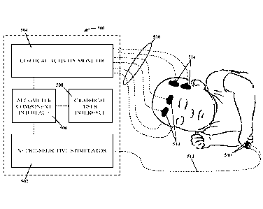
[0058] Figure 5 illustrates an example of a human algometer 500 according to a
non-limiting
embodiment of the present invention. That algometer 500 includes a neuro-
selective stimulator
502, a cortical activity monitor 504, a component interface 506, and a
graphical user interface
508. The neuro-selective stimulator 502 is configured to apply neuro-specific
stimulation to
specific nerve fibers (e.g., A13. A6, and C fibers) using specific voltages
and currents applied at
neuro-specific frequencies (i.e.. 2000, 250, and 5 Hz). The cortical activity
monitor 504 is
configured to monitor cortical activity based on hemodynamic and/or
neurophysiological
responses to the neuro-specific electrical stimulation generated by the neuro-
selective stimulator
502 and/or to other forms of stimulation. The component interface 506 is
configured to control
both the neuro-selective stimulator 502 and the cortical activity monitor 504,
to integrate the
functionality of those two components 502 and 504, and to store the data
obtained with those two
components 502 and 504. And the graphical user interface 508 is configured to
receive and
transmit data that is input by a user to control the neuro-selective
stimulator 502 and the cortical
activity monitor 504 and to analyze and display the data that is measured,
sampled, and stored
with those three components 502, 504, and 506.
[0059] Although the algometer 500 illustrated in Figure 5 is described
primarily in terms of
NIRS, EEG can be used instead of or in addition to NIRS without departing from
the spirit of the
present invention. Moreover, other suitable forms of cortical activity
monitoring (e.g., functional
Magnetic Resonance Imaging (fMRI), near infrared imaging (NMI), etc.) can be
used instead of
or in addition to NIRS and/or EEG without departing from the spirit of the
present invention.
But because the equipment required to perform MRS and EEG is generally less
cumbersome
than that utilized for other forms of cortical activity monitoring, and due at
least to the features of
-21-
CA 02795045 2012-09-28
WO 2011/126894 PCT/US2011/030546
MRS and EEG discussed above, the algometer 500 of the present invention
preferably utilizes
MRS and/or EEG.
i. Neuro- selective Stimulator 502
[0060] As Figure 6 illustrates, the neuro-selective stimulator 502 includes a
low-voltage circuit
600 and a high-voltage circuit 602. The low-voltage circuit 600 and the high-
voltage circuit 602
are both connected to a microprocessor 900 (Figure 9) in the component
interface 506. The low-
voltage circuit 600 includes a sine wave generator circuit 604, a digital
potentiometer circuit 606,
and a DC cancellation circuit 608. And the high-voltage circuit 602 includes a
precision non-
inverting operational amplifier (op-amp) 610, a first current mirror 612, a
second current mirror
614, a first high voltage current source 616, a second high voltage current
source 618, and
electrode inputs/outputs 620. The low-voltage circuit 600 generates a pure AC
sine wave signal
that is converted to a current-based signal by the high-voltage circuit 602.
[0061] In more detail, the microprocessor 900 is connected to the sine wave
generator circuit
604, which includes a low-power Direct Digital Synthesis (DDS) programmable
waveform
generator integrated circuit (IC). The microprocessor 900 sends commands
("Frequency Select"
in Figure 6) to the sine wave generator circuit 604 for generating different
signal frequencies
(e.g., 5, 250, and 2000 Hz) that correspond to the stimulus required to
activate different nerve
fibers (e.g.. C, AC), and A13 fibers). The microprocessor 900 also sends a
crystal referenced
mega-Hertz (MHz) clocking signal to the sine wave generator circuit 604, which
the sine wave
generator circuit 604 uses to generate the requisite sine wave signals with a
frequency accuracy
of 10 milli-Hertz (mHz).
[0062] The sine wave generator circuit 604 and the microprocessor 900 are both
connected to the
digital potentiometer circuit 606. The sine wave generator circuit 604 sends
the sine wave it
generates to the digital potentiometer circuit 606. And the microprocessor 900
sends commands
-22-
CA 02795045 2012-09-28
WO 2011/126894 PCT/US2011/030546
("Intensity Select" in Figure 6) to the digital potentiometer circuit 606 that
correspond to
different signal amplitudes, which are used by a voltage divider at the
digital potentiometer
circuit 606 to apply different signal amplitudes to the sine waves generated
by the sine wave
generator circuit 604. Those signal amplitudes are precisely controlled by the
microprocessor
900 so they can be used by the high-voltage circuit 602 to generate currents
with different
intensities (e.g., 0.5, 0.85, and 2.3 mA) that correspond to the stimulus
required to activate
different nerve fibers (e.g., C, AC), and Al3 fibers). The maximum intensity
generated by the
high-voltage circuit 602 is set such that only sub-noxious stimulus is applied
to a patient (i.e., an
intensity large enough to achieve the targeted nerve fiber's threshold action
potential but small
enough that the patient does not consciously perceive a feeling of pain).
[0063] The digital potentiometer circuit 606 is connected to the DC
cancellation circuit 608 and
sends the signals generated with the input from the microprocessor 900 and the
sine wave
generator circuit 604 to the DC cancellation circuit 608. The DC cancellation
circuit 608
removes the DC components from those signals, thereby producing a pure AC
signal with the
desired frequency and amplitude. The resulting voltage-based signal is then
sent to the high-
voltage circuit 602 for conversion into to a current-based signal.
[0064] The DC cancellation circuit 608 of the low-voltage circuit 600 is
connected to the non-
inverting input of the non-inverting op-amp 610 of the high-voltage circuit
602. A precision gain
resistor RGa,õ is connected to the inverting input of the non-inverting op-amp
610 through a
resistor-capacitor combination R6/C1. The DC cancellation circuit 608 sends
the voltage-based
sine wave signal generated with the input from the digital potentiometer
circuit 606 to the non-
inverting op-amp 610 while the gain resistor RGain is used to control the gain
of the high-voltage
circuit 602. The non-inverting op-amp 610 preferably has input bias currents
of less than a few
-23-
CA 02795045 2012-09-28
WO 2011/126894 PCT/US2011/030546
pico-amperes (pA), and the gain resistor RGain preferably has a resistance of
approximately 10
ohms.
[0065] The non-inverting op-amp 610 is connected to the first transistors Q2
and Q7 of the first
and second current mirrors 612 and 614. respectively. And the second
transistors Q1 and Q6 of
the first and second current mirrors 612 and 614 are connected to the gain
resistor RGain and the
non-inverting input of the non-inverting op-amp 610 through resistors R1 and
R5, respectively.
The first and second transistors Q and Q1 of the first current mirror 612 are
NPN transistors, and
the first and second transistors Q7 and Q6 of the second current mirror 614
are PNP transistors.
[0066] The second transistors Q1 and Q6 of the first and second current
mirrors 612 and 614 are
connected to the first transistors Q and Qlo of the first and second high
voltage current sources
616 and 618, respectively, and outputs of the first and second current mirrors
612 and 614 are
sent to the first and second high voltage current sources 616 and 618,
respectively. High voltage
sources +Hv (e.g., +400 V) and ¨Hv (e.g., ¨400 V) are connected to the second
transistors Q4
and Q, of the first and second high voltage current sources 616 and 618
through resistors R.) and
R10, respectively. And the third transistors Q5 and Qg of the first and second
high voltage current
sources 616 and 618 are connected to the electrode inputs/outputs 620 through
a resistor R, and a
pair of resistor-capacitor combinations R7/C2 and R8/C3 in series. The first,
second, and third
transistors Q3, Q4, and Q5 of the first high voltage current source 616 are
PNP transistors, and the
first, second, and third transistors Q10, Q9, and Qg of the second high
voltage current source 618
are NPN transistors. Together, the components of the high-voltage circuit 602
operate as a
voltage-to-current converter capable of generating current stimuli with
intensities of 10 mA and
greater.
[0067] The electrode inputs/outputs 620 of the high-voltage circuit 602 are
connected to a
-24-
CA 02795045 2012-09-28
WO 2011/126894 PCT/US2011/030546
current measuring resistor R ¨sense and to the microprocessor 900. The outputs
of the first and
second current mirrors 612 and 614 are combined and sent to the electrode
inputs/outputs 620
via the pair of resistor-capacitor combinations R7/C2 and R8/C3 to provide
further DC
cancellation and to compensation for changes in a patient's skin impedance.
And the resulting
current that is applied to a patient is measured through the measuring
resistor Rsense and sent back
to the microprocessor 900 for fine adjustment ("Feedback" in Figure 6). For
example, the
microprocessor 900 will automatically reduce the intensity of the current if
it is measured to be
higher than the current required to target the desired nerve fiber and/or
higher than the threshold
current for producing sub-noxious stimulation. In that way, the low-voltage
circuit 600 provides
precise control of the frequency and amplitude of the desired signal, and the
high-voltage circuit
602 provides precise voltage-to-current conversion.
[0068] The electrode inputs/outputs 620 are connected to electrodes 510
through corresponding
electrode cables 512. See, e.g., Figure 5. The electrodes 510 provide a
consistent, distortion free
interface between the neuro-selective stimulator 502 and a patient's skin. The
electrodes 510 are
preferably gold plated and paired together using a flexible spreader to
standardize the distance
between them. The electrodes are also preferably cupped to accommodate
electrode gel for
maintaining a consistent output current density for reliable, repeatable
results. The electrode
cables 512 are lightweight lead wires that are terminated with spring loaded
molded portions
configured to resiliently hold the electrodes 510. The electrodes 510 and
electrode cables 512
may be reusable or disposable and designed for single-use only. The algometer
500 is
configured to operate using commercially available electrodes 510 and
electrode cables 512,
which helps reduce the manufacturing and operational costs of the algometer
500.
ii. Cortical Activity Monitor 504
[0069] As Figure 7 illustrates, the cortical activity monitor 504 includes a
first current driver
-25-
CA 02795045 2012-09-28
WO 2011/126894 PCT/US2011/030546
circuit 700, a second current driver circuit 702, a first photo-detector
circuit 704, a second photo-
detector circuit 706, an analog multiplexer 708, and a high-resolution 16-bit
analog-to-digital
converter (ADC) 710. Like the low-voltage circuit 600 and the high-voltage
circuit 602 of the
neuro-selective stimulator 502, the different subcomponents 700-710 of the
cortical activity
monitor 504 are connected to the microprocessor 900. The first current driver
circuit 700
includes a first precision non-inverting op-amp 712, a red light emitter 714,
and a transistor Qii;
the second current driver circuit 702 includes a second precision non-
inverting op-amp 716, an
IR light-emitter 718, and a transistor Q12; the first photo-detector circuit
704 includes a first
photo-detector diode 720, a first trans-impedance op-amp 722, a first low-pass
filter (LPF) 724,
and a first voltage follower op-amp 726; and the second photo-detector circuit
706 includes a
second photo-detector diode 728, a second trans-impedance op-amp 730, a second
LPF 732, and
a second voltage follower op-amp 734. Red light and IR light are emitted from
the red and IR
light emitters 714 and 718 and the reflected light is detected by the first
and second photo-
detector diodes 720 and 728, respectively.
[0070] In more detail, the microprocessor 900 (Figure 9) of the component
interface 506 is
connected to the non-inverting input of the first non-inverting op-amp 712 and
the non-inverting
input of the second non-inverting op-amp 716 through resistors R13 and R14,
respectively. The
microprocessor 900 generates the requisite current excitation level for the
red and IR light
emitters 718 by selecting those resistors R13 and R14 to receive current ("Red
Select" and "IR
Select" in Figure 7, respectively) in an alternating manner. The resulting
voltage drops across
those resistors R13 and R14 are converted into currents by the first and
second current driver
circuits 700 and 702, and those currents cause the red light emitter 714 and
IR light emitter 718
to emit red light and IR light, respectively, in an alternating manner. The
microprocessor 900
-26-
CA 02795045 2012-09-28
WO 2011/126894 PCT/US2011/030546
controls the rate of emission and the delay between the red light emitter 714
and IR light emitter
718 as required to measure hemodynamic changes in the cortical regions of a
patient's brain.
For example, light emissions may be repeated at a rate of 125 Hz with a duty
cycle of 25% for
each light emitter 714 and 718.
[0071] The microprocessor 900 is also connected to the multiplexer 708, which
is connected to
outputs of the first and second current driver circuits 700 and 702 through
resistors R11 and R12,
respectively, The microprocessor 900 is also connected to the multiplexor 708
through the ADC
710. The multiplexer 708 receives the outputs of the first and second current
driver circuits 700
and 702 ("Red Input Current" and "IR Input Current" in Figure 7,
respectively), samples those
outputs, and forwards them to the ADC 710. The ADC 710 converts the analog
current outputs
from the first and second cuiTent driver circuits 700 and 702 into digital
signals and sends those
signals to the microprocessor 900, where they are analyzed and temporarily
stored. For example,
the microprocessor 900 will determine the length, frequency, and intensity of
each signal,
identify those signals as separate stimulus cycles, and temporarily store that
data on RAM before
sending it to the graphical user interface 508 for further processing. Those
digital signals
represent the input currents to the red and IR light emitters 714 and 718,
which correspond to the
amount of red and IR light emitted by the red and IR light emitters 714 and
718. respectively.
[0072] The outputs of the first and second photo-detector circuits 704 and 706
are also connected
to the multiplexer 708. As the red and IR light that is emitted by the red and
IR light emitters
714 and 718 propagates subcutaneously in a patient's skull, it is
differentially absorbed at one
end of the path of propagation by skin, brain tissues, and hemoglobin and
cytochrome aa3 in the
cerebral vasculature of the patient's brain. At the other end of the path of
propagation, the red
and IR light that is not absorbed by genetic material is received by the first
and second photo-
-27-
CA 02795045 2012-09-28
WO 2011/126894 PCT/US2011/030546
detector diodes 720 and 728. Each of the first and second photo-detector
diodes 720 and 728
converts the received light into an electrical signal by generating a current
that is proportional to
the amount of light that it receives (i.e., the amount of photons it absorbs).
That current is
received by the corresponding trans-impedance op-amp 722 or 730 and
transformed into a
voltage. Because that current can be very small with a very small signal to
noise ratio, the first
and second trans-impedance op-amps 722 and 730 each preferably have extremely
large input
impedance with input currents in the pico-ampere (pA) range, which provides
very precise
amplification.
[0073] The output voltages of the first and second trans-impedance op-amps 722
and 730 are
sent through the first and second LPFs 724 and 732, respectively, so as to
further remove noise
from those output voltages. The order of the first and second LPFs 724 and 732
and the position
of their poles are selected to remove noise while maintaining the integrity of
the resulting signal
at the cortical activity monitor's 504 operating frequency (e.g., 125 Hz). The
output voltages
then pass through the first and second voltage follower op-amps 726 and 734 to
eliminate
loading effects. The multiplexer 708 receives the resulting output voltages
("Red Output
Voltage" and "IR Output Voltage" in Figure 7, respectively), samples them, and
forwards them
to the ADC 710.
[0074] The ADC 710 converts the analog voltage outputs from the first and
second photo-
detector circuits 704 and 706 into digital signals and sends those signals to
the microprocessor
900, where they are analyzed and temporarily stored. For example, the
microprocessor will
collect fifty data points from each photo-detector circuit 704 and 706,
average those data points,
and temporarily store them in RAM before sending them to the graphical user
interface 508 for
further processing. Those digital signals represent the amount of current
generated at the first
-28-
CA 02795045 2012-09-28
WO 2011/126894 PCT/US2011/030546
and second photo-detector diodes 720 and 728, which correspond to the amount
of red and IR
light received by the first and second photo-detector diodes 720 and 728,
respectively. And by
comparing the amount of red and IR light received by first and second photo-
detector diodes 720
and 728 with the amount of red and IR light emitted by the red and IR light
emitters 714 and
718, the microprocessor 1000 (Figure 10) of the graphical user interface 508
is able to measure
the amount of hemodynamic change that occurs over time in the cortical regions
of a patient's
brain.
[0075] The red light emitter 714, the IR light emitter 718, the first photo-
detector diode 720, and
the first photo-detector diode 728 are provided as part of a single NIRS
sensor 514 that is
connected to the algometer 500 through a corresponding sensor cable 516. See,
e.g., Figure 5.
The NIRS sensor 514 is configured to couple to a patient's skin tissue
adjacent to a cortical
region of the patient's brain so that red and IR light can be propagated into
those cortical regions
by the red and IR light emitters 714 and 718 and so that the reflected red and
IR light can be
received by the first and second photo-detector diodes 720 and 728,
respectively. The red light
emitter 714 is configured to emit red light with a wavelength that corresponds
to the absorption
spectra of deoxyhemoglobin (i.e., 730-775 nm); the IR light emitter 718 is
configured to emit IR
light with a wavelength that corresponds to the absorption spectra of
deoxyhemoglobin (e.g.,
850-900 nm): the first photo-detector diode 720 is configured to generate a
current that is
proportional to the amount of light it receives in the red light wavelength
spectrum (i.e., 600-750
nm); and the second photo-detector diode 728 is configured to generate a
current that is
proportional to the amount of light it receives in the IR light spectrum
(i.e., 750-1000 nm). In the
alternative, one or both of the first and second photo-detector diodes 720 and
728 may be
configured to generate a current based on the amount of light they receive in
both of those
-29-
CA 02795045 2012-09-28
WO 2011/126894 PCT/US2011/030546
wavelength spectrums (i.e., 600-1000 nm).
[0076] The red light emitter 714 and the IR light emitter 718 may include
separate
semiconductor diode elements, or dies, that emit light at different
wavelengths within their
respective wavelength spectrums. For example, the IR light emitter 718 may
include one die that
emits light at wavelengths centered around 910 nm and another that emits light
at wavelengths
centered around 810 nm. Similarly, a single light-emitting diode (LED) may
include both the
red light emitter 714 and the IR light emitter 718 as well as their respective
dies. For example, a
single LED may include a die for the red light emitter 714 that emits light at
wavelengths
centered around 730 nm and an IR light emitter 718 according to the previous
example. When
more than two dies are provided to generate light at more than two wavelengths
in that manner,
one or more additional driver circuits 700 or 702 will be provided in the
cortical activity monitor
504 to generate the required excitation currents to cause the extra die or
dies to emit that light.
[0077] Regardless of the number of different wavelengths of light the red
light emitter 714 and
the IR light emitter 718 are configured to generate, the red light emitter 714
and the IR light
emitter 718 and their respective dies are preferably provided in a single LED.
And the first and
second photo-detector diodes 720 and 728 are preferably configured to generate
a current based
on the amount of light they receive in both of the red and lR wavelength
spectrums (i.e., 600-
1000 nm). In that way, both the LED and the first and second photo-detector
diodes 720 and 728
can be used interchangeable to generate and receive light at all of the
available wavelengths,
which provides greater flexibility when configuring the NIRS sensor 514.
[0078] Figure 8A illustrates an exemplary NIRS sensor 514 that includes a
single LED 800 with
includes both the red light emitter 714 and the IR light emitter 718 provided
therein, as well as
their respective dies. Because the mean penetration depth of photons is
proportional to the
-30-
CA 02795045 2012-09-28
WO 2011/126894 PCT/US2011/030546
distance between the emitting source and the receiving detector, the LED 800
is preferably
placed a shorter distance A to the first photo-detector diode 720 than the
distance B to the second
photo-detector diode 728, wherein the second photo-detector diode 728 is
preferably larger than
the first photo-detector diode 720 to compensate for that larger distance B.
That configuration
creates two different propagation paths with two different path lengths ¨ a
short path from the
red and IR light emitters 714 and 718 to the first photo-detector diode 720
and a longer path from
the red and IR light emitters 714 and 718 to the second photo-detector diode
728. The shorter
path measures hemodynamic changes within the skin, muscle, and bone of a
patient's head while
the longer path measures those hemodynamic changes as well as hemodynamic
changes in the
cortical regions of the patient's brain. And the measurement (MA) taken with
the first photo-
detector diode 720 via the short path can then be subtracted from the
measurement (MB) taken
with the second photo-detector diode 728 via the long path to isolate the
measurement (Mcorticai)
at the cortical region of the patient's brain (i.e., MB ¨ MA = MCorticai).
[0079] Unfortunately, any variation in the skin, muscle, and/or bone between
the locations at
which the first and second photo-detector diodes 720 and 728 are placed can
introduce error into
those measurements. Accordingly, the NIRS sensor 514 preferably includes a
second LED 802
that also includes both a red light emitter 714 and an IR light emitter 718 as
well as their
respective dies. As Figure 8B illustrates, that configuration allows two pair
of propagation paths
with different path lengths to be created, wherein the first LED 800 is placed
a shorter distance A
to the first photo-detector diode 720 than the distance B to the second photo-
detector diode 728
and the second LED 802 is placed a shorter distance A' to the second photo-
detector diode 728
than the distance B' to the first photo-detector diode 720. Because both the
first and second
photo-detector diodes 720 and 728 absorb photons from both a short and long
path, they are both
-31-
CA 02795045 2012-09-28
WO 2011/126894 PCT/US2011/030546
preferably large enough to operate effectively for both of those path lengths.
[0080] The measurement (MA) taken with the first photo-detector diode 720 via
the shorter path
to the first LED 800 is subtracted from the measurement (MB) taken with the
second photo-
detector diode 728 via the longer path to the first LED 800 and the
measurement (MA') taken
with the second photo-detector diode 728 via the shorter path to the second
LED 802 is
subtracted from the measurement (MB') taken with the first photo-detector
diode 720 via the
longer path to the second LED 802 to isolate the measurement (Mcorticap at the
cortical region of
the patient's brain (i.e., (MB ¨ MA) + (MB' ¨ MBA') = M cal,
=corti 1 In that way, the dual emitter/dual
detector configuration of Figure 8B accounts for variations in the skin,
muscle, and/or bone
between the locations at which the first and second photo-detector diodes 720
and 728 are
placed. And, as described in U.S. Patent No. 7,865,223 to Bernreuter, the
spacing between the
first and second LEDs 800 and 802 and the first and second photo-detector
diodes 720 and 728
can be modified or changed as required to optimize measurements at different
tissue depths.
Moreover, as also described in that patent, the additional measurements
provided by that dual-
emitter/dual detector configuration can be taken alternately at three
different wavelengths to
further remove surface effects. The disclosure of that patent is hereby
incorporated by reference
in its entirety as if fully set forth herein.
[0081] Regardless of the configuration of the NIRS sensors 514, they may be
reusable or
disposable and designed for single-use only. The sensor cables 516 may be
provided separately
from or integrated with the NIRS sensors 514 and may be reusable or
disposable. For example,
the NIRS sensors 514 of Figures 8A and 8B may be disposable with reusable
sensor cables 516,
disposable with integrated disposable sensor cables 516, or reusable with
integrated reusable
sensor cables 516. The algometer 500 is configured to operate using
commercially available
-32-
CA 02795045 2012-09-28
WO 2011/126894 PCT/US2011/030546
MRS sensors 514 and sensor cables 516, which helps reduce the manufacturing
and operational
costs of the algometer 500.
[0082] Although only one NIRS sensor 514 is discussed in detail above, the
algometer 500 is
configured to utilize multiple NIRS sensors 514 at different locations on a
patient's head as
required to measure hemodynamic changes at different cortical regions (e.g.,
the occipital cortex,
the primary somatosensory cortex, the secondary somatosensory cortex, the
insular cortex, the
dorsolateral prefrontal cortex, the parietal cortex, etc.) on different
patients (e.g., adults, children,
infants, neonates, lab animals, etc.). And although only two current driver
circuits 700 and 702
and two photo-detector circuits 704 and 706 are discussed in detail above, the
algometer 500
includes a corresponding number of current driver circuits 700 and 702 and
photo-detector
circuits 704 and 706 to the number of NIRS sensors 514 and dies in their
respective LEDs 800
and 802. In Figure 5, for example, six NIRS sensors 514 are provided that each
have two LEDs
800 and 802 with three dies. Accordingly, the cortical activity monitor 504 in
Figure 5 has
thirty-six current driver circuits (6 NIRS sensors x 2 LEDs/NIRS sensor x 3
dies/LED x 1 current
driver circuit/die = 36 current driver circuits) and twelve photo-detector
circuits (6 NIRS sensors
x 2 photo-detector circuits/NIRS sensor = 12 photo-detector circuits).
Component Interface 506
[0083] As Figure 9 illustrates, the component interface 506 includes the
microprocessor 900 that
is shared by the neuro-selective stimulator 502 and the cortical activity
monitor 504. As
discussed above, the microprocessor controls the neuro-selective stimulator
502 and the cortical
activity monitor 504 and integrates the functionality of those components 502
and 504. The
component interface 506 also includes memory 902, a peripheral interface
adapter (PIA) 904,
and a power bus 906. The memory 902 stores the software that is executed by
the
microprocessor 900 and the data that is generated with the neuro-selective
stimulator 502 and the
-33-
CA 02795045 2012-09-28
WO 2011/126894 PCT/US2011/030546
cortical activity monitor 504; the PIA 904 provides a connection via which the
microprocessor
900 can electronically communicate with external devices; and the power bus
906 provides a
common source of power for operating the microprocessor 900, the neuro-
selective stimulator
502, and the cortical activity monitor 504.
[0084] In more detail, the memory 902 includes read-only memory (ROM) and
random-access
memory (RAM). ROM is a non-volatile memory chip where the essential system
instructions
(i.e., basic input/output system (BIOS) instructions) are permanently stored.
Those instructions
control the operations and interactions of the neuro-selective stimulator 502
and the cortical
activity monitor 504. And RAM is a volatile memory chip where portions of
those instructions
are temporarily stored before they are carried out by the microprocessor 900.
The
microprocessor 900 may also temporarily store other data on the RAM, such as
the data
generated with the neuro-selective stimulator 502 and the cortical activity
monitor 504. Such
data can be temporarily stored on the RAM, for example, prior to sending it to
the graphical user
interface 508 for further processing.
[0085] The PIA 904 is a specialized interface chip that provides parallel
in/out interfacing
capability for the microprocessor 900, thereby allowing the algometer 500 to
be connected to
peripherals, such as printers or monitors. It may also allow the algometer 500
to be connected to
a hospital's central monitoring system. When the graphical user interface 508
is provided as a
separate computing device from the algometer 500 (e.g., a personal computer,
laptop computer,
tablet computer, etc.), the PIA 904 will provide interfacing capability with
that device.
Accordingly, the memory 902 will include the requisite instructions stored on
the ROM for
facilitating one or more of those types of interfaces. And the algometer 500
will include an
appropriate connection port for connecting to such external devices (e.g., an
RS-232 connection,
-34-
CA 02795045 2012-09-28
WO 2011/126894 PCT/US2011/030546
an R.145 connection, a universal serial bus (USB) connection, a coaxial cable
connection, etc.).
[0086] Although not illustrated, the component interface 506 includes a set of
specialized signal
generating chips that are controlled by the microprocessor 900. For example,
the component
interface 506 may include a digital-to-analog converter (DAC) for converting
digital signals into
voltage or current as required to perform various tasks, such as generating
the requisite current
excitation level to cause the red light emitter 714 and IR light emitter 718
to emit red light and
IR light, respectively. Those chip sets serve to alleviate the microprocessor
900 from the burden
of digital signal generation, thereby freeing the microprocessor 900 to
perform sign al processing
of the data generated with the neuro-selective stimulator 502 and the cortical
activity monitor
504. Moreover, they can be used to perform tasks that would otherwise be
performed by
complex circuits in the algometer, such the first and second current driver
circuits 700 and 702,
thereby allowing the size and complexity of the algometer 500 to be
significantly reduced.
iv. Graphical User Interface
[0087] As Figure 10 illustrates, the graphical user interface 508 includes its
own microprocessor
1000 and its own memory 1002. It also includes a user input device 1004, and a
display device
1006. The microprocessor 1000 controls the overall operation of the algometer
500; the memory
1002 stores data and software used to by the microprocessor 1000 to control
the overall
operation of the algometer 100; the input device 1004 receives input from a
user to set the
parameters for performing different tests with different patients; and the
display device 1006
displays the data input into and generated by the various components 502-508
of the algometer
500. Those subcomponents 1000-1006 of the graphical user interface 508 work
together to
coordinate and automate stimulation algorithms and response detection at a
patient's
somatosensory cortex and other cortical regions of the patient's brain, and to
perform data
capture, storage, and processing.
-35-
CA 02795045 2012-09-28
WO 2011/126894 PCT/US2011/030546
[0088] In more detail, the microprocessor 1000 communicates with the memory
1002, input
device 1004, and display device 1006 of the graphical user interface 508 and
the microprocessor
of the component interface 506 as required to generate, gather, and analyze
pain data. The
microprocessor 1000 receives input from a user via the input device 1004 and
selects which
algorithms to perform from the software stored on the memory 1002. For
example, a user can
utilize the input device 1004 (e.g., a keyboard, a touchscreen, a mouse, etc.)
to select the type of
analysis that the algometer 500 will perform (e.g., determining SDTs,
determining a pain score,
monitoring the effects of an analgesic, etc.) and the parameters that will
define any variables that
will affect that analysis (e.g., patient age, type of NIRS sensor 514 being
used, location of NIRS
sensors 514, type of electrodes 510 being used, location of electrodes 510,
type of EEG electrode
1100 being used, location of EEG electrodes 1100, etc.). The microprocessor
1000 will then
initiate the selected type of analysis by sending a command to the
microprocessor 900 of the
component interface 506, which will then generate the appropriate electrical
stimulation with the
neuro-selective stimulator 502 and generate the appropriate light emissions
with the cortical
activity monitor 504.
[0089] As the microprocessor 900 of the component interface 506 identifies the
separate
stimulus cycles generated by the neuro-selective stimulator 502 and averages
the data points
collected by the cortical activity monitor 504, it will temporarily store that
data on its RAM and
periodically send that data back to the microprocessor 1000 of the graphical
user interface 508 in
packets for further processing and extended storage. Those packets of data
will identify the
frequency and intensity of the electrical stimulation applied by the
electrodes 510, the current
levels at which red and IR light are emitted by the red and IR light emitters
714 and 718, and the
currents detected by the photo-detector diodes 720 and 728. And the
microprocessor 900 of the
-36-
CA 02795045 2012-09-28
WO 2011/126894 PCT/US2011/030546
component interface 506 will send those packets of data to the microprocessor
1000 of the
graphical user interface 508 after each of a series of concurrent loops of
electrical stimulation
and N1RS and/or EEG are performed. The microprocessor 1000 of the graphical
user interface
508 will then analyze that data using its own processing loop based on the
type of analysis
selected and the parameters input via the input device 1004. Those loops are
described in more
detail below with respect to the algometer software.
[0090] The microprocessor 1000 dynamically displays the results of that
analysis at the display
device 1006 in a relevant numerical (e.g., a recorded SDT value, a calculated
pain score, etc.),
verbal (e.g., a written outcome, a written warning, etc.), and/or graphical
(e.g., a plot of pain
response, a pain scale graph, etc.) format. The microprocessor 1000 may also
dynamically
display the values of the electrical stimulation applied with the neuro-
selective stimulator 502
(e.g., frequency, intensity, cycle time, etc.) and/or the values of
hemodynamic and/or
neurophysiological changes measured with the cortical activity monitor 504
(e.g., threshold
oxygenation and/or electrical activity values, somatosensory oxygenation
and/or electrical
activity values, change in oxygenation and/or electrical activity values,
etc.) in a similar manner.
In that way, a user (e.g., a qualified healthcare provider) can monitor a
patient's physiological
response to the electrical stimulation in a meaningful numerical, verbal,
and/or graphical format,
which allows that user to make accurate clinical decisions regarding pain and
pain management.
In fact, the algometer 500 may even be connected to other medical devices
(e.g., a drug-
dispensing system) and programmed to control those medical devices based on
the patient's
physiological response (e.g., decreasing or increasing dosing from the drug-
dispensing machine).
[0091] The microprocessor 1000 stores the data received from the neuro-
selective stimulator 502
and the cortical activity monitor 504 (via the microprocessor 900 of the
component interface
-37-
CA 02795045 2012-09-28
WO 2011/126894 PCT/US2011/030546
506) and the results of the analysis in the memory 1002 of the graphical user
interface 508. That
data (e.g., stimulus frequency and intensity, hemodynamic and/or
neurophysiological change,
pain scores, SDT values, etc.) is associated with the specific patient on whom
the analysis was
performed, codified, and stored in a secure manner for later retrieval or
communication into an
electronic health record (EHR) system and/or for subsequent review. That data
is associated
with a specific patient based on the data input into the graphical user
interface 508 via the input
device 1004, which can include the patient's name and/or identifying
information. And that data
can be communicated to an EHR system wirelessly via a wireless interface,
using a connection
made via the PIA 904 of the component interface 506, using a connection made
via a PIA (not
shown) in the graphical user interface 508, or using a portable storage medium
(e.g., a rewritable
disk, a flash drive, etc.).
[0092] The graphical user interface 508 includes a separate microprocessor
1000 from the
component interface 506 to further alleviate the burden of complex processing
at the
microprocessor 900 of the component interface 506, thereby freeing that
microprocessor 900 to
primarily function for processing the data generated with the neuro-selective
stimulator 502 and
the cortical activity monitor 504. Moreover, it allows the graphical user
interface 508 to be
provided as a separate computing device (e.g., a personal computer, a laptop
computer, a tablet
computer, etc.) from the neuro-selective stimulator 502, the cortical activity
monitor 504, and the
component interface 506. In that configuration, the graphical user interface
508 could be
connected to the neuro-selective stimulator 502, the cortical activity monitor
504, and the
component interface 506 via the PIA 904 of the component interface 506,
thereby allowing the
algometer 500 to operate with any of a wide variety of different computing
devices serving as the
graphical user interface 508.
-38-
CA 02795045 2012-09-28
WO 2011/126894 PCT/US2011/030546
[0093] Similarly, any of the different components of the algometer 500 (i.e.,
neuro-selective
stimulator 502, the cortical activity monitor 504, the component interface
506, and the graphical
user interface 508), or subcomponents thereof (e.g., current driver circuits
700 and 702, photo-
detector circuits 704 and 706, memory 1002, input device 1004, display device
1006, etc,), may
also be provided as separate, stand-alone devices. Moreover, any of those
components 502-508,
or subcomponents 600, 602, 700-710, 902-906, and 1002-1006, can be in wireless
data
communication with each other via a wireless interface. For example, the
current driver circuits
700 and 702, the photo-detector circuits 704 and 706, a wireless communicator,
and an
independent power source may be provided in or near an NIRS sensor 514 so that
the NIRS
sensor 514 can operate independently of and in wireless data communication
with the other
subcomponents 708 and 710 of the cortical activity monitor 504, thereby
eliminating the need for
sensor cables 516 between the algometer 500 and the NIRS sensors 514. Such
wireless
communications can occur via any suitable wireless technology (e.g., Wi-Fi,
BLUETOOTH
brand wireless technology, radio frequency (RF), etc.).
[0094] Because the microprocessor 1000 of the graphical user interface 508
performs more
complex processing than the microprocessor 900 of the component interface 506,
such as
generating dynamic displays at the graphical user interface and executing the
various process
loops defined by the algometer software, it is preferably faster than the
microprocessor 900 of
the component interface 506 (e.g., > 2.8 GHz). It also and preferably has at
least 4 MB of cache
memory and at least 4 GB of RAM to support fast processing. And because the
memory 1002 of
the graphical user interface stores data for a plurality of patients over
different time frames, it
preferably includes at least 100 GB of solid state data storage. Providing the
memory 1002 as a
solid state storage device increases process and storage cycles and reduces
the chances of hard
-39-
CA 02795045 2012-09-28
WO 2011/126894 PCT/US2011/030546
drive failure, as experienced with conventional spinning platen type hard
drives
D. Algometer Software
[0095] The integrated components 502-506 of the algometer 500 can be used to
(1) objectively
quantify pain and the response to noxious and sub-noxious stimuli, (2)
determine SDTs and/or
pain scores in response to such stimuli and other clinically relevant stimuli,
(3) monitor the
analgesic effects of drugs and other pain interventions and the efficacy and
dose-response
relationships of newly developed and/or investigational drugs targeted for the
management of
pain, (4) determine the onset of tolerance to analgesic and other
interventions, and (5) provide a
diagnostic characterization of pain, all of which guide the overall management
of pain in a
patient. That functionality is controlled by the software stored on the memory
1002 of the
graphical user interface 508. And the microprocessor 1000 executes the
instructions on that
software to perform the various tasks required to provide that functionality.
[0096] In more detail, the software includes stimulation algorithms that
automate and coordinate
simultaneous and self-consistent control of the sub-noxious electrical
stimulation applied with
the neuro-selective stimulator 502 and the hemodynamic and/or biopotential
measurements
performed with the cortical activity monitor 504. Which of those algorithms
are executed by the
microprocessor 1000 is determined by the data input by a user at the input
device 1004 of the
algometer 500. A user can not only select from among the four functions listed
above, he or she
can also choose such things as the nerve fiber that will be targeted (e.g.,
AP, A6, Or C fibers), the
length of time stimulation will be applied (e.g., 1 second, 10 seconds, 15
seconds, or 20 seconds,
etc.), the location of the electrodes 510 (e.g., left arm, left leg, left
foot, etc.), the location of the
NIRS sensors 514 and/or EEG electrodes 1100 (e.g., the occipital cortex, the
primary
somatosensory cortex, the dorsolateral prefrontal cortex, etc.), the location
of the patient's pain
(e.g., left arm, left leg, left foot, etc.), the developmental stage (e.g.,
neonate, child, adult, etc.)
-40-
CA 02795045 2012-09-28
WO 2011/126894 PCT/US2011/030546
and/or age of the patient (e.g., 30 weeks postmenstrual, 2-5 years, > 65 years
. etc.), weight of the
patient (e.g., X pounds, 100-125 pounds, 125-150 pounds, etc.), sex of the
patient (e.g., male or
female), any pertinent physical/medical condition of the patient (e.g.,
hyperalgesia, opioid
addiction, heart condition, etc.), and/or any current or intended therapeutic
intervention (e.g.,
opioids, alpha-2 agonists, etc.).
[0097] Each of those selections can play a factor in how the neuro-selective
stimulator 502 needs
to apply neuro-specific electrical stimulation (i.e., the frequency and/or
intensity of electrical
stimulation may need to be adjusted slightly for certain patients) and how the
cortical activity
monitor 504 measures hemodynamic and/or neurophysiological responses (i.e.,
the location
and/or type of MRS sensors 514 and/or the wavelength of light may need to be
different for
certain patients, and/or the location and/or type of EEG electrodes 1100
and/or the frequency of
electrical activity measured may need to be different for certain patients).
And the algometer
software includes algorithms that are configured to make the appropriate
adjustments based on
those various selections. For example, the distance between NIRS sensors 514
is determined by
age, which determines, in part, the differential pathlength factor (DPF) and
the algorithm used to
measure hemodynamic changes at a given wavelength.
[0098] Some of those selections might result in instructions for the user
being displayed on the
display device 1006 of the algometer 500. For example, a user can select to
monitor the effects
of an opioid on an adult patient, which will result in the display device 1006
displaying
instructions for placing the electrodes 510 on an extremity that is not the
source of the patient's
pain (e.g., segment C7), placing the NIRS sensors 514 on the occipital cortex
and somatosensory
cortex of the patient (e.g., between T3 and T5, between C3 and P3, between P3
and 01, and
between P4 and 01), and/or placing EEG electrodes 1100 on the occipital cortex
and
-41-
CA 02795045 2012-09-28
WO 2011/126894 PCT/US2011/030546
somatosensory cortex of the patient (e.g., a P3, Pz, P4, 01, and 02). Those
instructions can
include a graphical display to better guide the user in placing the electrodes
510, NIRS sensors
514, and/or EEG electrodes 1100, such as the graphical displays illustrated in
Figures 11A and
11B. And those selections will result in a current with a frequency of 5 Hz
and an intensity of
0.50-0.80 mA chosen as the appropriate current to apply to that patient. That
frequency and
intensity are specific to C fibers, which are modulated by opioids. After the
user has placed the
electrodes 510, NIRS sensors 514, and/or EEG electrodes 1100 as instructed, he
or she can
instruct the algometer 500 to begin applying that neuro-specific electrical
stimulation with the
electrodes 510 and monitoring hemodynamic and/or neurophysiological responses
with the NIRS
sensors 514 and/or EEG electrodes 1100.
[0099] While neuro-specific electrical stimulation is being applied with the
electrodes 510 and
hemodynamic and/or neurophysiological responses are being monitored with the
NIRS sensors
514 and/or EEG electrodes 1100, the microprocessor 1000 in the graphical user
interface 508
will begin analyzing the data as it is received from the microprocessor 900 in
the component
interface 506. Those concurrent tasks are performed based on three separate
process loops
defined by the algometer software ¨ a control/analysis loop, a stimulation
loop, and a monitoring
loop. The embedded structure of those loops is described hereinafter, starting
from the outer-
most loop and then followed by the inner loops.
i. Control/Analysis Loop
[0100] As Figure 12 illustrates, the outer-most loop is the control/analysis
loop, the middle loop
is the stimulation loop, and the inner-most loop is the monitoring loop. The
control/analysis loop
controls the microprocessor 1000 of the graphical user interface 508 and calls
the inner loops
directly or indirectly to initialize and coordinate the actions of the neuro-
selective stimulator 502
and the cortical activity monitor 504, to gather data generated by those
components, and to
-42-
CA 02795045 2012-09-28
WO 2011/126894 PCT/US2011/030546
deactivate those components after the desired data is obtained. The
control/analysis loop also
analyzes that data in real time as it is being generated by the neuro-
selective stimulator 502 and
the cortical activity monitor 504 and instructs the display device 1006 to
display portions of that
data as it is generated and analyzed.
[0101] The following sequence list describes an exemplary control/analysis
loop process
performed by the graphical user interface 508:
1. Initialize (boot) the algometer's 500 components 502-508, perform internal
system
diagnostics, log/report system status, and initiate user graphical user
interface 508
(unless system errors indicate a device malfunction requiring attention);
2. Initialize graphical user interface 508 for receiving user input via the
input device
1004 for selecting the desired function and setting patient-specific
parameters;
3. Provide instructions to user for placing electrodes 510, NIRS sensors 514,
and/or
EEG electrodes 1100 based on input received via the input device 1004;
4. Provide power to the neuro-selective stimulator 502, the cortical activity
monitor 504,
and component interface 506 via the power bus 906 and instruct the
microprocessor
900 of the component interface 506 to place them in ready and wait mode:
a. Initialize low-voltage circuit 600 and high voltage circuit 602 of the
neuro-
selective stimulator 502,
b. Initialize current driver circuits 700 and 702, photo-detector circuits 704
and 706,
multiplexor 708, and ADC 710 of cortical activity monitor 504, and
c. Initialize timers in microprocessor 900, memory 902, and PIA 904 of the
component interface 506;
5. Select algorithm based on user input and use it to select cycle time and
neuro-specific
frequency and intensity of electrical stimulation and to select parameters of
oximetry
based on user input;
6. Receive instructions from user to begin applying neuro-specific electrical
stimulation
with the electrodes 510 and monitoring hemodynamic and/or neurophysiological
responses with the NIRS sensors 514 and/or EEG electrodes 1100;
7. Instruct the microprocessor 900 of the component interface 506 to begin
monitoring
hemodynamic and/or neurophysiological changes with the cortical activity
monitor
504:
-43-
CA 02795045 2012-09-28
WO 2011/126894 PCT/US2011/030546
a. Initiate measuring loop to collect baseline measurement of cortical
activity
without neuro-specific electrical stimulation being applied (see discussion of
monitoring loop provided below), and
b. Send the data collected by the microprocessor 900 of the component
interface 506
(NIRS and/or EEG data only) to the microprocessor 1000 of the graphical user
interface 508 for further processing in the analysis/control loop;
8. Quantify collected data and store as a baseline value for the patient in
the memory
1002;
9. Instruct the microprocessor 900 of the component interface 506 to begin
applying
neuro-specific electrical stimulation to the patient with the neuro-selective
stimulator
502:
a. Initiate stimulation loop to apply electrical stimulation with a neuro-
specific
frequency and intensity for a predetermined cycle time (see discussion of
stimulation loop provided below).
b. Start timing length of time electrical stimulation is applied with clock
timer at the
microprocessor 1000 of the graphical user interface 508,
c. If the data received by the microprocessor 900 at the component interface
506
indicates that the neuro-specific electrical stimulation is being applied with
an
intensity above a sub-noxious level, instruct the microprocessor 900 of the
component interface 506 to stop applying neuro-specific electrical stimulation
to
the patient with the neuro-selective stimulator 502, else instruct the
microprocessor 900 of the component interface 506 to stop applying neuro-
specific electrical stimulation to the patient with the neuro-selective
stimulator
502 after the clocking timer indicates that a predetermine amount of time has
elapsed since the electrical stimulation began,
d. Start timing length of time electrical stimulation is NOT applied with
clock timer
at the microprocessor 1000 of the graphical user interface 508,
e. After a predetermine amount of time has passed since the electrical
stimulation
stopped, repeat steps a-d for a predetermined number of stimulation cycles
before
instructing the microprocessor 900 of the component interface 506 to stop
applying neuro-specific electrical stimulation to the patient with the neuro-
selective stimulator 502, and
f. Send the data collected by the microprocessor 900 of the component
interface 506
(NIRS and/or EEG data plus stimulation data) to the microprocessor 1000 of the
graphical user interface 508 for further processing in the analysis/control
loop,
and
-44-
CA 02795045 2012-09-28
WO 2011/126894 PCT/US2011/030546
10. Quantify collected data, compare to baseline value, and store as a neuro-
specific
hemodynamic and/or neurophysiological response for the patient in the memory
1002
of the graphical user interface 508;
11. If comparison determines that the value of the neuro-specific response is
more than a
predetermined amount greater than the baseline value, instruct the
microprocessor
900 of the component interface 506 to repeat steps 9 and 10 a predetermined
number
of times using the same neuro-specific frequency and intensity, else instruct
the
microprocessor 900 of the component interface 506 to repeat steps 9 and 10
using
electrical stimulation with a greater neuro-specific intensity;
12. Convert the quantified value of the NIRS and/or EEG data into a meaningful
measure
of the patient's pain-related cortical activity;
13. Instruct the microprocessor 900 of the component interface 506 to stop
monitoring
hemodynamic and/or neurophysiological changes with the cortical activity
monitor
504;
14. Store quantified value as an objective pain measurement for patient in the
memory
1002 of the graphical user interface 508;
15. Generate dynamic display of results on display device 1006.
Figure 13 is a flow chart illustrating the steps of that exemplary process.
[0102] As set forth in those steps and Figure 13, the control/analysis loop
initiates the measuring
loop and uses the cortical activity monitor 504 to establish a baseline amount
cortical activity
based on hemodynamic and/or neurophysiological changes occurring in a
patient's cortical
regions when no neuro-specific electrical stimulation is being applied with
the neuro-selective
stimulator 502. After that baseline is established, control/analysis initiates
the stimulation loop
and uses the neuro-selective stimulator 502 apply neuro-specific electrical
stimulation to the
patient while the cortical activity monitor 504 continues monitoring the
hemodynamic and/or
neurophysiological changes occurring in the patient's cortical regions. The
neuro-specific
electrical stimulation is applied in on-off cycles (i.e., a period of
simulation being applied
followed a period of stimulation NOT being applied) that are repeated a
predetermined number
of times (e.g., 50) at a neuro-specific frequency and intensity (e.g., 2000 Hz
and 2.2 mA). The
-45-
CA 02795045 2012-09-28
WO 2011/126894 PCT/US2011/030546
length of those on-off stimulation cycles will vary according to the patient-
specific variables
input with the input device 1004 (e.g., location of stimulus, medical or
physical condition of
patient, etc.) but will typically last a few seconds and will always
incorporate an "off' period
and an "on" period in each cycle. That series of on-off stimulation cycles is
hereinafter referred
to as a "frequency cycle" because they are all applied at the same neuro-
specific frequency
according to the nerve fiber being targeted (e.g., 5 Hz for C fibers. 250 Hz
for M fibers, and
2000 Hz for AP fibers).
[0103] After data has been gathered for a frequency cycle, the
control/analysis loop analyzes that
data with the microprocessor 1000 of the graphical user interface 508 to
determine whether a
threshold level of sub-noxious stimulation has been experienced by the
patient. If the threshold
level of sub-noxious stimulation is experienced, the stimulation loop will
repeat the frequency
cycle a predetermined number of times. Otherwise, the microprocessor 1000 of
the graphical
user interface 508 will instruct the microprocessor 900 of the component
interface 506 to
increase the intensity of the neuro-specific electrical stimulation being
applied with the neuro-
selective stimulator 502 and perform a frequency cycle at that new intensity
(e.g., 2000 Liz and
2.3 mA). The intensity will be increased incrementally until the threshold
level of sub-noxious
stimulation is experienced, at which point the stimulation loop will repeat
the frequency cycle at
that neuro-specific frequency and intensity a predetermined number of times.
[0104] The control/analysis loop continuously gathers data with the cortical
activity monitor 504
during each frequency cycle and analyzes it to provide an objective measure of
pain experienced
by the patient to whom the neuro-specific electrical stimulation was applied.
More specifically,
the microprocessor 1000 of the graphical user interface 508 quantifies the
value of the MRS data
(i.e., the differential infrared absorption data reflecting neuro-specific
changes in hemodynamic
-46-
CA 02795045 2012-09-28
WO 2011/126894 PCT/US2011/030546
response parameters) and/or EEG data (i.e., the differential electrical
activity data representing
neuro-specific changes in biopotential response parameters) measured by the
cortical activity
monitor 504 into a meaningful measure of the patient's pain-related cortical
activity (e.g., a pain
score, an SDT, etc.). For example, an average measured change in total
hemoglobin (HbT) of
5.2 umol/L during a frequency cycle could be correlated to an SDT value of 8
on a scale of 1 to
12. A similar correlation can be performed using Fisher's Z values when EEG is
used in
combination with or in place of NIRS. That objective pain measurement is then
stored for that
patient on the memory 1 002 of the graphical user interface 508.
[0105] A similar process can be implemented with the algometer 500 of the
present invention
using noxious stimulation (e.g., surgery, venipuncture, arterial puncture,
heel-lance, intravenous
cannulation, endotracheal tube introduction, endotracheal tube suctioning,
gavage insertion for
feeding, removal of electrode leads and tape, etc.) manually applied by a user
in a clinical
setting. In that instance, the stimulation loop will be omitted or utilized
prior to that manually
applied noxious stimulation. For example, a user can select a function with
the input device
1004 of the graphical user interface 508 in which the exemplary process
described above will be
used to determine the SDT and then repeated without applying neuro-specific
electrical
stimulation to determine a pain score based on the cortical activity measured
in response to the
manually applied noxious stimulation. In that example, the user would receive
instructions on
the appropriate time(s) to manually apply the noxious stimulation via the
display device 1006 so
as to coordinate the noxious stimulation with the time that the cortical
activity monitor 504 will
measure the patient's cortical activity. And the microprocessor 1000 of the
graphical user
interface will quantify that cortical activity with a pain score, using the
patient's previously
determined SDT as a reference measurement. The patient's cortical activity
with no stimulation
-47-
CA 02795045 2012-09-28
WO 2011/126894 PCT/US2011/030546
being applied will serve as the baseline for both the SDT and the pain score.
In that manner,
baseline and SDT values can be determined in patients before clinical
interventions and serve as
valuable comparators for calculating pain scores after manually applied
noxious stimulation.
[0106] Those baseline and SDT values may also be used to determine the effects
of analgesics
and other pain interventions. In that instance, the exemplary process
described above will be
repeated over time in a patient who is receiving an intervention intended to
treat pain and used to
determine that patient's SDT at different points during that treatment. The
microprocessor 1000
of the graphical user interface 508 will store those SDT values with the
corresponding dosage
information on the memory 1002 of the graphical user interface 508 and compare
those values
over time to identify the onset of tolerance to the intervention or the onset
of analgesic-induced
toxicity in the patient. For example, the onset of tolerance to analgesics
will be identified when
there is a trend of increased analgesic dosage amounts over time while
maintaining the same
SDT. And the onset of hyperalgesia will be identified when there is a trend of
decreased SDTs
over time while maintaining the same analgesic dosage amounts.
ii. Stimulation Loop
[0107] The stimulation loop controls the microprocessor 900 of the component
interface 506 and
the neuro-selective stimulator 502 and provides electrical stimulation at
frequencies that
selectively stimulate specific sensory nerve fibers (e.g., C, AC), and A 13
fibers) so as to elicit
specific activity in a patient's cortical regions ¨ in particular, those
associated with the patient' s
somatosensory system. The microprocessor 900 of the component interface 506
and the low-
voltage circuit 600 and high voltage circuit 602 of the neuro-selective
stimulator 502 are
initialized at step 4 of the control/analysis loop. And the following sequence
list describes an
exemplary stimulation loop process performed by the microprocessor 900 of the
component
interface 506 and the neuro-selective stimulator 502 at step 9 of the
control/analysis loop:
-48-
CA 02795045 2012-09-28
WO 2011/126894 PCT/US2011/030546
1. Receive instructions from the microprocessor 1000 of the graphical user
interface 508
to begin applying electrical stimulation at a neuro-specific frequency and
intensity;
2. Configure sine wave generator 604 to begin producing continuous sine wave
signals
at neuro-specific frequency selected at step 5 of the control/analysis loop;
3. Configure digital potentiometer 606 to begin applying an initial voltage
output of zero
to the sine wave signals;
4. Select "on" and "off' times of neuro-specific electrical stimulation
according to the
cycle time selected at step 5;
5. Start timing length of time voltage output of digital potentiometer 606 is
zero with
clock timer at the microprocessor 900 of the component interface 506;
6. Configure digital potentiometer 606 to begin applying a voltage output to
the sine
wave signals that corresponds to the neuro-specific intensity selected at step
5 of the
control/analysis loop after the selected "off' time has elapsed;
7. Start timing length of time voltage output of digital potentiometer 606 is
at the
neuro-specific intensity with clock timer at the microprocessor 900 of the
component
inteiface 506;
8. Configure digital potentiometer 606 to begin applying a voltage output of
zero to the
sine wave signals after the selected "on" time has elapsed;
9. Repeat steps 5-8 for a predetermined number of on-off stimulation cycles;
10. Notify microprocessor 1000 of the graphical user interface 508 that on-off
stimulation
cycles are completed and wait for further instruction;
11. If comparison at step 10 of control/analysis loop determines that the
value of the
neuro-specific response is more than a predetermined amount greater than the
baseline value, receive instructions from the microprocessor 1000 of the
graphical
user interface 508 to repeat steps 6-9 a predetermined number of times using
the same
neuro-specific frequency and intensity, else receive instructions from the
microprocessor 1000 of the graphical user interface 508 to repeat steps 6-9
using
electrical stimulation with a greater neuro-specific intensity.
Figure 14 is a flow chart illustrating the steps of that exemplary process.
[00100] As set forth in those steps and Figure 14, the microprocessor 1000
of the
graphical user interface 508 sends instructions to the microprocessor 900 of
the component
interface 506 to begin applying electrical stimulation at a neuro-specific
frequency and intensity.
Based on those instructions, the microprocessor 900 of the component interface
506 instructs the
-49-
CA 02795045 2012-09-28
WO 2011/126894 PCT/US2011/030546
sine wave generator 604 to begin producing continuous sine wave signals at
that frequency and
instructs the digital potentiometer 606 to begin applying a voltage to those
signals. The initial
voltage is zero, but that voltage is ramped up to a voltage that corresponds
to a neuro-specific
intensity. As discussed above, that neuro-specific voltage is converted to a
neuro-specific
current by the high-voltage circuit 602 of the neuro-selective stimulator 502.
[0108] Based on the on-off cycle times selected by the microprocessor 1000 of
the graphical user
interface 508, neuro-selective stimulator 502 cycles between "on" and "off'
periods or neuro-
specific electrical stimulation until a predetermined number of on-off cycles
(e.g., 50) are
completed. At that point, the stimulation loop will stop until reinitiated by
the control/analysis
loop which, as discussed above, may include selecting an incrementally larger
current intensity
with which to generate the neuro-specific electrical stimulation. And as also
discussed above the
control/analysis loop will stop and reinitiate the stimulation loop a
predetermined number of
times until the desired number of frequency cycles are completed. The
stimulation loop will also
stop if the current applied via the electrodes 510 is detected as being higher
than a predetermined
value, such as a current with an intensity large enough to achieve the
targeted nerve fiber's
threshold action potential but small enough that the patient does not
consciously perceive a
feeling of pain (i.e.õ > sub-noxious stimulation).
[0109] The cycle times, number cycle sequences, minimum and maximum current
intensities,
and degrees of increase in current intensities are determined by the algorithm
selected by the
microprocessor 1000 of the graphical user interface 508 based on the user
input received via the
input device 1004. The number of frequency cycles is selected to provide a
sufficient number of
data points to provide statistical accuracy when quantifying the pain
perceived by the patient.
And if the maximum current intensity is reached without the minimum threshold
response to
-50-
CA 02795045 2012-09-28
WO 2011/126894 PCT/US2011/030546
stimulation being observed, that maximum current intensity will be stored in
the memory 1002
of the graphical user interface 508 as the threshold amount. Thus, if an SDT
is being determined
with the algometer 500, that value will be used to calculate the patient's
SDT.
Monitoring Loop
[0110] The monitoring loop controls the microprocessor 900 of the component
interface 506 and
the cortical activity monitor 504 and provides an objective measurement of
pain based on
hemodynamic and/of neurophysiological changes in the cortical regions of a
patient's brain in
response to the sub-noxious, neuro-specific electrical stimulation applied
with the neuro-
selective stimulator 502 and/or manually applied noxious stimulation. The
microprocessor 900
of the component interface 506 and the subcomponents 700-710 of the cortical
activity monitor
504 are initialized at step 4 of the control/analysis loop. And the following
sequence list
describes an exemplary monitoring loop process performed by the microprocessor
900 of the
component interface 506 and the neuro-selective stimulator 502 at steps 7-13
of the
control/analysis loop:
1. Initialize first clock timer at the microprocessor 900 of the component
interface 506
for generating control signals to alternately select which of the red and IR
light
emitters 714 and 718 will receive an excitation current;
2. Alternately generate requisite current excitation level for the red and IR
light emitters
714 and 718 within current driver circuits 700 and 702 based on the control
signals
from the first timer:
3. Initialize second clock timer at the microprocessor 900 of the component
intetface
506 for generating control signals to alternately select which channel of the
multiplexer 708 to be processed by the ADC 710;
4. Alternately sample and convert signals from first current driver circuit
700, second
current driver circuit 702, first photo-detector circuit 704, and second photo-
detector
circuit 706 with the ADC 710 based on the channel of the multiplexer selected
with
the control signals from the second timer;
Figure 15 is a flow chart illustrating the steps of that exemplary process.
-51-
CA 02795045 2012-09-28
WO 2011/126894 PCT/US2011/030546
[0111] As set forth in those steps and Figure 15, the microprocessor 1000 of
the graphical user
interface 508 sends instructions to the microprocessor 900 of the component
interface 506 to
begin alternately generating red and IR light with the red and IR light
emitters 714 and 718 of the
first and second current driver circuits 700 and 702. The microprocessor 1000
of the graphical
user interface 508 also sends instructions to the microprocessor 900 of the
component interface
506 to begin alternately sampling the signals generated at the first current
driver circuit 700,
second current driver circuit 702, first photo-detector circuit 704, and
second photo-detector
circuit 706 as the red and IR light emitters 714 and 718 emit red and IR light
and the first and
second photo-detectors 720 and 728 receive the reflected portions of that
light. Those two
alternating cycles are performed continuously until the microprocessor 1000 of
the graphical user
interface 508 sends instructions to the microprocessor 900 of the component
interface 506 to stop
the monitoring loop.
[0112] The first timer preferably generates 25% duty cycle pulses at 125Hz
frequency to
enable/disable the activation of the red and IR emitters 714 and 718. The
second timer
preferably has a 0.5 ms period at which time a new channel of the multiplexer
708 is selected by
the for analog-to-digital conversion by the ADC 710. And each cycle of light
emission
preferably lasts 2 ms such that the four channels of the multiplexer are
interleaved to provide
signals to the ADC 710 in increments of 0.5 ms. In that configuration, the
microprocessor 900 of
the component interface 506 gathers fifty data-points during each interleaved
0.5 ms sample,
averages them, and sends sixteen sets of those averaged data points to the
microprocessor of the
graphical user interface 508 every 8 ms for further processing. Each of those
average data points
includes values of input currents to the red and IR light emitters 714 and 718
and values of
currents detected at the first and second photo-detector diodes 720 and 728.
-52-
CA 02795045 2012-09-28
WO 2011/126894 PCT/US2011/030546
E. Human Algometry
[0113] In practice, the algometer of the present invention can be used to (1)
objectively quantify
pain and the response to noxious and sub-noxious stimuli, (2) determine SDTs
and/or pain scores
in response to such stimuli and other clinically relevant stimuli, (3) monitor
the analgesic effects
of drugs and other pain interventions and the efficacy and dose-response
relationships of newly
developed and/or investigational drugs targeted for the management of pain,
(4) determine the
onset of tolerance to analgesic and other interventions, and (5) provide a
diagnostic
characterization of pain, all of which guide the overall management of pain in
a patient. Each of
those forms of human algometry is discussed separately below.
i. Objective Quantification of Pain
[0114] The cortical activity monitoring functionality of the present invention
allows the
emotional component of pain to be separated from the actual, nociceptive
component of pain.
The emotional component of pain is removed by using the neuro-selective
stimulator 502 to
generate action potentials at specific nerve fibers without the patient
perceiving nociception (i.e.,
sub-noxious electrical stimulation). Although the resulting innervations of
those nerve fibers is
not perceived by the patient, the cortical activity monitor 504 of the present
invention is able to
measure hemodynamic and/or neurophysiological changes in the cortical regions
of the patient's
brain in response to that stimuli. Because those measurements are able to
separate the
nociceptive component of pain from the emotional component of pain and do not
require
subjective verbal quantifications and/or subjective physician observations,
they provide an
objective measure of the patient's response to the sub-noxious electrical
stimulation.
[0115] The emotional component of pain can be further removed from that
measurement by
monitoring cortical activity at the specific cortical region of the brain
associated with nociceptive
pain (i.e., the primary somatosensory cortex) and the specific cortical region
of the brain
-53-
CA 02795045 2012-09-28
WO 2011/126894 PCT/US2011/030546
associated with emotional pain (i.e., the dorsolateral prefrontal cortex). The
hemodynamic
and/or neurophysiological changes at those two regions are then correlated
with one another to
determine the relationship between the emotional component and the nociceptive
component.
Thus, if a patient is actually perceiving pain, either as a result of the
noxious stimulation being
manually applied and/or the patient's physical condition, the emotional
component can be
factored out of the nociceptive component to provide a more accurate, and more
objective,
measure of the patient's actual, nociceptive pain.
ii. Determining SDTs and Pain Scores
[0116] The present invention uses a testing paradigm that differs from
conventional
apparatus/methods, such as PPT and PTT, in that the determination of SDTs and
pain scores
utilizing neuro-specific electrical stimulation of self-limiting duration for
which the intensity is
controlled based on objective measurements of hemodynamic and/or
neurophysiological changes
measured with the cortical activity monitor 504. A compilation of hemodynamic
and/or
neurophysiological responses to commonly encountered, clinically relevant
painful or noxious
stimuli along with control (e.g., no stimulation) or other reference responses
are used to create a
pain scale against which SDTs and/or pain scores can be evaluated and
reported. That testing
paradigm also allows for the inclusion of manually applied noxious
stimulation, which can be
separated from its emotional component to provide an objective measurement of
nociceptive
pain, as discussed above. SDT values and pain scores can be assigned to a
patient at specific
frequencies and intensities of electrical stimulation using a look-up table,
or scale, stored on the
memory 1002 of the graphical user interface 508 to identify an SDT value or
pain score
associated with the measured amount of hemodynamic and/or neurophysiological
change for that
patient at those frequencies and intensities of electrical stimulation,
Different look-up tables are
provided for different patients based on known physiological differences
between those patients
-54-
CA 02795045 2012-09-28
WO 2011/126894 PCT/US2011/030546
so as to form a library of reference responses that can be used to determine
pain scores and/or
SDTs for patients.
[0117] As Figure 16 illustrates, those look-up tables are defined via clinical
evaluations (e.g.,
clinical trials, patient encounters, etc.). More specifically, the cortical
activity monitor 504 is
used to measure hemodynamic and/or neurophysiological changes in the cortical
regions of a
plurality of different patient's brain as a plurality of different levels of
stimulation are applied to
the patient. That stimulation includes noxious stimulation, and it may be
applied either with the
neuro- sel ecti ve stimulator 502 with conventional thermal, chemical, or
mechanical stimuli.
Because the neuro-selective stimulator 502 will generally not be used to apply
anything other
than sub-noxious stimulation, it will have a separate "clinical trial" mode
that is configured to
allow it to be used to apply noxious stimulation during clinical trials. That
mode will also be
configured to receive input via the input device 1004 of the graphical user
interface for
quantifying the pain experienced by the patient. Those quantifications will be
matched with the
measured level of hemodynamic and/or neurophysiological changes measured with
the cortical
activity monitor 504 to identify a range of SDT values for different patients
with different
physiological characteristics (e.g., patients of different age, weight,
medical condition, medical
history, etc.).
[0118] The ranges of SDT values determined for different patients are used to
create the look-up
tables. And the ranges in those loop-up tables are used to identify SDTs for
subsequently
evaluated patients by matching the measured levels of hemodynamic and/or
neurophysiological
changes for those subsequently evaluated patients to values in the loop-up
tables that correspond
to the SDTs obtained for previously evaluated patients with similar
physiological characteristics
to the subsequently evaluated patients. As Figure 16 illustrates, and as
discussed above with
-55-
CA 02795045 2012-09-28
WO 2011/126894 PCT/US2011/030546
respect to the control/analysis loop of the algometer software, the process of
subsequently
evaluating patients using those loop-up tables includes measuring a baseline
level of
hemodynamic and/or neurophysiological changes in the patient without any
stimulation being
applied to use as a control. Neuro-specific electrical stimulation is then
applied with the neuro-
selective stimulator 502 until hemodynamic and/or neurophysiological changes
are measured
with the cortical activity monitor 504 that fall within the subject SDT range.
The corresponding
frequency and intensity of the neuro-specific electrical stimulation used to
obtain that threshold
level of hemodynamic and/or neurophysiological change in the patient is then
associated with
that patient's SDT and stored on the memory 1002 of the graphical user
interface 508 for use in
future evaluations of that patient.
[0119] Because the evaluations used to define the look-up tables include the
application of
noxious pain, they are preferably performed during clinical evaluations
specifically designed to
establish SDT ranges for different patients with different physiological
characteristics. The
algometer 500 is then pre-programmed with the appropriate look-up tables
before being used in
other clinical settings. Accordingly, the algometer 500 can be utilized in
those other clinical
settings to apply sub-noxious stimulation only. Look-up tables for pain scores
can be defined
and used in substantially the same manner.
Monitoring Effects and Efficacy of Drugs and Pain Interventions
[0120] The ability of the present invention to monitor hemodynamic and/or
neurophysiological
changes in response to neuro-specific electrical stimulation allows the
present invention to
determine the analgesic effects drugs and other pain interventions as well as
the efficacy and
dose-response relationships of newly developed and/or investigational drugs
targeted for the
management of pain. More specifically, different analgesic drug classes
modulate different
nerve fibers. And by targeting those specific fibers with neuro-specific
electrical stimulation, the
-56-
CA 02795045 2012-09-28
WO 2011/126894 PCT/US2011/030546
present invention is able to evaluate the effect of the specific drug that
modulates those nerve
fibers.
[0121] For example, opioids modulate C fibers but not AP fibers. Accordingly,
neuro-specific
electrical stimulation can be applied to C fibers at a frequency of 5 Hz to
measure the effect of an
opioid. And by utilizing that neuro-specific electrical stimulation in
conjunction with the
objective measurements provided by the cortical activity monitor 504 of the
present invention,
the effects of analgesic drugs and other pain interventions can be measured in
specific sensory
nerve fibers. Thus, the present invention can be used with a quantitative
sensory testing (QST)
paradigm to objectively measure pain responses to specific pain interventions.
[0122] As Figure 17 illustrates, the SDT values provided in the look-up tables
described above
can be used as part of testing the effect of a specific pain intervention. In
that figure, the cortical
activity monitor 504 is used to begin measuring the pain a patient is
experiencing before a pain
intervention is administered, such as immediately after a patient has
undergone a surgical
procedure. At that point, no electrical stimulation is applied with the neuro-
selective stimulator
502. The pain intervention is then administered, and the hemodynamic and/or
neurophysiological changes in the cortical regions of the patient's brain are
measured until they
drop below the patient's SDT. That drop in measurements indicates that the
pain intervention
was effective.
[0123] After the hemodynamic and/or neurophysiological changes are below the
patient's SDT
for a predetermined amount of time, neuro-specific electrical stimulation is
applied to the patient
with the neuro-selective stimulator 502 using a frequency specific to the
nerve fiber modulated
by the subject pain intervention (e.g., 5 Hz for an opioid). The electrodes
510 are placed on an
extremity that is not the source of the patient's pain (e.g., finger, toe,
etc.) so as to measure the
-57-
CA 02795045 2012-09-28
WO 2011/126894 PCT/US2011/030546
systemic effect of the analgesic on a particular nerve fiber type rather than
on the source of the
patient's pain. And the current is maintained at an intensity within the SDT
range determined for
the patient so that hemodynamic and/or neurophysiological changes below that
threshold value
will indicate that that the pain intervention is acting effectively and
hemodynamic and/or
neurophysiological changes at or above that threshold value will indicate that
the pain
intervention is wearing off.
[0124] In response to such an indication, the algometer 500 can generate an
alert, such as
displaying a warning on the display device 1006 of the graphical user
interface, it can
communicate with a drug-dispensing system to cause that system to
automatically re-administer
the pain intervention in the appropriate amount, and/or it can communicate
with a hospital's
central monitoring system to generate an alert at some other location, such as
a nurses station.
As a result of those alerts or that communication with the drug-dispensing
system, the pain
intervention will be re-administered to the patient. The algometer 500 will
continue to monitor
the patient's pain and re-administer the pain intervention in that way as
required to ensure the
patient's pain remains below a noxious level.
iv. Determining the Onset of Tolerance
[0125] The present invention can determine the onset of tolerance to certain
pain interventions
by repeating the processes illustrated in Figures 16 and 17 over an extending
period of time. The
process illustrated in Figure 16 is intermittently repeated within a specific
dosing to identify
changes in the patient's SDT, and the process of Figure 17 is continuously
repeated to determine
the effectiveness of the pain intervention in response to that dosing. The
patient's SDT can then
be adjusted over time so that the point where the pain intervention is wearing
off can be more
accurately identified. And when a decrease in the patient's SDTs is exhibited
over time in
response to similar intensities of neuro-specific electrical stimulation, the
onset of tolerance will
-58-
be identified. The algometer 500 can generate alerts or adjust dosing when it
identifies the onset of
tolerance in a similar manner to that described above when a pain intervention
needs to be re-
administered.
v. Diagnostic Characterization of Pain
[0126] The ability of the present invention to monitor hemodynamic and/or
neurophysiological
changes in response to neuro-specific electrical stimulation also allows the
present invention to
make a diagnostic characterization of pain in various pain conditions. More
specifically, different
pain conditions modulate different nerve fibers. And by targeting those
specific fibers with neuro-
specific electrical stimulation, the present invention is able to diagnose the
pain condition the
patient is experiencing.
[0127] For example, because neuropathic pain is modulated via AP fibers.
Accordingly, neuro-
specific electrical stimulation can be applied to Ap fibers at a frequency of
2000 Hz to detect the
presence of neuropathic pain over an injury. In that instance, the electrodes
510 will be placed over
the area on the patient's body that is the source of the pain. And a
measurement of noxious or near-
noxious levels of pain in response to sub-noxious neuro-specific stimulation
of AP fibers ¨
sensory fibers generally not associated with nociceptive pain ¨ at the source
of the patient's pain
will indicate that the patient is suffering neuropathic pain. Similar
techniques can be used to
diagnose other pain conditions (e.g., hyperalgesia, allodynia, etc.).
F. Supplemental Disclosure
[0128] In addition to the foregoing disclosure, the disclosures of the
following articles are noted:
1. American Medical Association, "Module 6: Pediatric Pain Management", Pain
Management Series, http://www.ama-cmeonline.com/pain mgmt/modu1e06
/index.htm (February 2010);
- 59 -
CA 2795045 2017-07-18
CA 02795045 2012-09-28
WO 2011/126894 PCT/US2011/030546
2. Angst, M. S., D. R. Drover, et al., "Pharmacodynamics of orally
administered
sustained- release hydromorphone in humans". Anesthesiology, vol, 94(1), 63-73
(2001);
3. Bartocci, M., L. L. Bergqvist, et al.. "Pain activates cortical areas in
the preterm
newborn brain". Pain, 122(1-2), 109-117 (2006);
4. Becerra, L. et al. "Diffuse Optical Tomography Activation in the
Somatosensory
Cortex: Specific Activation by Painful vs. Non-Painful Thermal Stimuli", PLoS
ONE, vol. 4(11), 1-5 (2009);
5. Becerra, L. et al. "Diffuse Optical Tomography of Pain and Tactile
Stimulation:
Activation in Cortical Sensory and Emotional Systems", Neuroimage, vol. 41(2),
252-259 (2008);
6. Bornhovd, K., M. Quante, et al., "Painful stimuli evoke different stimulus-
response
functions in the amygdala, prefrontal, insula and somatosensory cortex: a
single-trial
fMRI study", Brain, vol. 125(6), 1326-1336 (2002);
7. Brennum, J., J. B. Dahl, et at., "Quantitative sensory examination of
epidural
anaesthesia and analgesia in man: effects of pre- and post-traumatic morphine
on
hyperalgesia", Pain, vol. 59(2). 261-271 (1994);
8. Carbajal, R. et al., "Epidemiology and Treatment of Painful Procedures in
Neonates
in Intensive Care Units", JAMA, vol. 300(1), 60-70 (2008);
9. De Pascalis. V. and Cacace, I., "Pain perception, obstructive imagery and
phase-
ordered gamma oscillations", Int. J. Psychophysiology, vol. 56(2). 157-169
(2005);
10. Finkel, J. C., V. G. Besch, et al., "Effects of aging on current
vocalization threshold in
mice measured by a novel nociception assay", Anesthesiology, vol. 105(2), 360-
369
(2006);
11. Finkel, J. C., C. I. Yang, et al., "Neuro-selective sensory
electrodiagnostic evaluation
of 4% liposomal topical lidocaine", Anesth Analg, vol. 94(5), 1259-1262, Table
of
Contents (2002);
12. Gustorff, B., K. H. Hoerauf, et al., "Comparison of different quantitative
sensory
testing methods during remifentanil infusion in volunteers", Br J Anaesth.
vol. 91(2),
203-208 (2003);
13. Hoshi, Y. and Tamura, M., 'Dynamic multichannel near-infrared optical
imaging of
human brain activity", American Physiological Society. 1842-1846 (1993);
14. Kalinowski, M. and Wagner, H., "Sedation and pain management in
interventional
radiology", Adjunctive Therapy, 14-18;
-60-
CA 02795045 2012-09-28
WO 2011/126894 PCT/US2011/030546
15. Katims, J. J., "Electrodiagnostic Functional Sensory Evaluation of the
Patient with
Pain: A Review of the Neuroselective Current Perception Threshiold and Pain
Tolerance Threshold", Pain Digest, vol. 8, 219-230 (1998);
16. Katims, J. J., "Neuro-selective current perception threshold quantitative
sensory test",
Muscle Nerve, vol. 20(11), 1468-1469 (1997);
17. Katims, J. J., D. M. Long, et al., "Transcutaneous nerve stimulation:
Frequency and
waveform specificity in humans", Appl Neurophysiol, vol. 49(1-2), 86-91
(1986);
18. Kiso, T., Y. Nagakura, et al., "Neurometer measurement of current stimulus
threshold
in rats", J Pharmacol Exp Ther, vol. 297(1), 352-356 (2001);
19. Koga, K., H. Furue, et al., "Selective activation of primary afferent
fibers evaluated
by sine-wave electrical stimulation", Mol Pain, vol. 1(1), 13(2005);
20. Liu, S., D. J. Kopacz, et al,, "Quantitative assessment of differential
sensory nerve
block after lidocaine spinal anesthesia", Anesthesiology, vol. 82(1), 60-63
(1995):
21. Liu, S. S., J. C. Gerancher. et al.. "The effects of electrical
stimulation at different
frequencies on perception and pain in human volunteers; epidural versus
intravenous
administration of fentanyl", Anesth Analg, vol. 82(1), 98-102 (1996);
22. Lotsch, J. and M. S. Angst, "The -opioid agonist remifentanil attenuates
hyperalgesia evoked by blunt and punctuated stimuli with different potency: a
pharmacological evaluation of the freeze lesion in humans", Pain, vol 102(1-
2), 151-
161 (2003);
23. Luginbuhl, M., T. W. Schnider, et al., "Comparison of five experimental
pain tests to
measure analgesic effects of alfentanil", Anesthesiology, vol. 95(1), 22-29
(2001);
24. MacLeon, David B., "Calibration and Validation of the Nonin Non-invasive
Regional
Oximeter with Cerebral Sensor", Press Release (www.nonin.com).
25. Maltseva, I., et al., "Alpha oscillations as an indicator of dynamic
memory operations
¨ anticipation of omitted stimuli", Int. J. Psychophysiology, vol. 36(3), 185-
197
(2000);
26. McGowan, J.C. and S. K. Wallace, "Synergy of a Combined Near-Infrared
Spectroscopy and Blood Oxygenation Level-Dependent Functional Activation
Study," American Journal of Neuroradiology, 1127-1128 (Aug. 25, 2004);
27. Oda, M., N. Kitagawa, et al., "Quantitative and fiber-selective evaluation
of dose-
dependent nerve blockade by intrathecal lidocaine in rats", J Pharmacol Exp
Ther,
vol. 312(3), 1132-1137 (2005):
28. Owen-Reece, H., M. Smith, et al.. "Near infrared spectroscopy". Br J
Anaesth, vol,
82(3), 418-426 (1999);
-61-
CA 02795045 2012-09-28
WO 2011/126894 PCT/US2011/030546
29. Pedersen, J. L. and H. Kehlet, -Secondary hyperalgesia to heat stimuli
after bum
injury in man," Pain, vol. 76(3). 377-384 (1998);
30. Posner, J., A. Telekes, et al., "Effects of an opiate on cold-induced pain
and the CNS
in healthy volunteers," Pain, vol. 23(1). 73-82 (1985);
31. Slater, R., S. Boyd, et al., "Cortical pain responses in the infant
brain," Pain, vol.
123(3), 332; Author Reply 332-334 (2006);
32. Slater, R., A. Cantarella, et al., "Cortical pain responses in human
infants," J
Neurosci, vol. 26(14), 3662-3666 (2006);
33. Slater, R., M. Fitzgerald, et al., "Can cortical responses following
noxious stimulation
inform us about pain processing in neonates?," Semin Perinatol, vol. 31(5),
298-302
(2007);
34. Tai. K. and Chau, T., "Single-trial classification of NIRS signals during
emotional
induction tasks: towards a corporeal machine interface", Journal of
NeuroEngineering
and Rehabilitation, col. 6(39), 1-14 (2009);
35. Tay, B., M. S. Wallace, et al., "Quantitative assessment of differential
sensory
blockade after lumbar epidural lidocaine," Anesth Analg, vol. 84(5), 1071-1075
(1997);
36. Tobias, J. D,, "Cerebral oxygenation montoring: near-infrared
spectroscopy," Future
Drugs. 235-243 (2006);
37. Wolf, M. and Greisen, G., "Advances in Near- Infrared Spectroscopy to
Study the
Brain of the Preterm and Term Neonate", Clin Perinatol, col. 36, 807-834
(2009);
38. Wray, S., M. Cope, et al., "Characterization of the near infrared
absorption spectra of
cytochrome aa3 and haemoglobin for the non-invasive monitoring of cerebral
oxygenation," Biochim Biophys Acta, vol. 933(1), 184-192 (1988); and
39. Yamitsky, D., E. Sprecher, et al., "Multiple session experimental pain
measurement,"
Pain, vol. 67(2-3), 327-333 (1996).
G. Summary
[0129] The present invention integrates a neuro-selective stimulator 502 for
assessing the
physiological integrity of specific sensory pain fiber pathways with a
cortical activity monitor
504 for detecting cerebral responses to both sub-noxious and noxious stimuli.
The present
invention integrates those components using a central microprocessor 900 that
automates the
delivery of stimuli and the assessment of a patient's response to that
stimuli. The neuro-selective
-62-
CA 02795045 2012-09-28
WO 2011/126894 PCT/US2011/030546
stimulator 502 delivers escalating intensities of electrical stimulation at a
set of specific
frequencies and intensities that can be sensed by specific sensory nerve
fibers (i.e., neuro-
specific electrical stimulation). The r cortical activity monitor 504 uses
NIRS and/or EEG to
sample hemodynamic and/or neurophysiological changes in various cortical
regions of a
patient's brain, including but not limited to the primary somato sensory
cortex, the occipital
cortex, and the dorsolateral prefrontal cortex, in order to quantify the
responses to both sub-
noxious and noxious stimuli, either which may automatically be delivered by
the neuro-selective
stimulator 502 or manually delivered during the conduct of clinical care (e.g.
venipuncture,
surgical pain, endotracheal tube suctioning, dressing changes, etc.). In turn,
the response signals
are processed and an SDT and/or pain score are generated.
[0130] Placing NIRS probes and/or EEG electrodes 1100 at the various cortical
regions of the
brain enables the recognition and determination of distinct sensory (e.g.,
somatosensory cortex),
visual (e.g., occipital cortex), and emotional (e.g., dorsolateral prefrontal
cortex) responses to
various stimuli. Obtaining measurements of NIRS and/or EEG responses from
various regions
of the brain serves to differentiate the components of the human response to
noxious stimuli,
such as the nociceptive and emotional components of pain, and provides
baseline and/or control
measurements to such responses. The processing of those signals ultimately
provides for (1)
objectively quantifying pain and the response to noxious and sub-noxious
stimuli, (2)
determining SDTs and/or pain scores in response to such stimuli and other
clinically relevant
stimuli, (3) monitoring the effects of analgesic and other interventions
intended to treat pain,
(4) determining the onset of tolerance to analgesic and other interventions,
and (5) providing a
diagnostic characterization of pain, all of which guide the overall management
of pain in a
patient.. The resulting algometer 500 is compact with a graphical user
inteiface 508 and display
-63-
CA 02795045 2012-09-28
WO 2011/126894 PCT/US2011/030546
device 1006 that is easily incorporated into a variety of clinical
environments and that can be
used in combination with or adjunct to other diagnostic modalities.
-64-